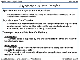
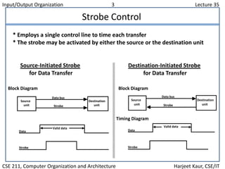
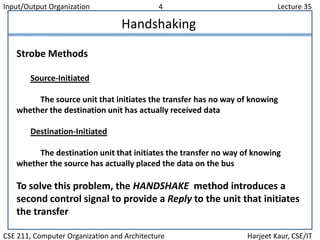
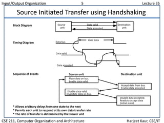
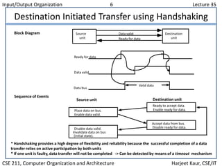
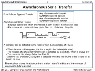
Input/Output Organization 1 Lecture 35
CSE 211, Computer Organization and Architecture Harjeet Kaur, CSE/IT
Overview
 Peripheral Devices
 Input-Output Interface
 Asynchronous Data Transfer
 Modes of Transfer
 Priority Interrupt
 Direct Memory Access
 Input-Output Processor
 Serial Communication
Input/Output Organization 2 Lecture 35
CSE 211, Computer Organization and Architecture Harjeet Kaur, CSE/IT
Asynchronous Data Transfer
Asynchronous data transfer between two independent units requires that
control signals be transmitted between the communicating units to
indicate the time at which data is being transmitted
Strobe pulse
- A strobe pulse is supplied by one unit to indicate the other unit when the
transfer has to occur
Handshaking
- A control signal is accompanied with each data being transmitted to
indicate the presence of data
- The receiving unit responds with another control signal to acknowledge
receipt of the data
Synchronous and Asynchronous Operations
Asynchronous Data Transfer
Two Asynchronous Data Transfer Methods
Synchronous - All devices derive the timing information from common clock line
Asynchronous - No common clock
Input/Output Organization 3 Lecture 35
CSE 211, Computer Organization and Architecture Harjeet Kaur, CSE/IT
Strobe Control
* Employs a single control line to time each transfer
* The strobe may be activated by either the source or the destination unit
Source
unit
Destination
unit
Data bus
Strobe
Data
Strobe
Valid data
Block Diagram
Source-Initiated Strobe
for Data Transfer
Source
unit
Destination
unit
Data bus
Strobe
Data
Strobe
Valid data
Block Diagram
Destination-Initiated Strobe
for Data Transfer
Timing Diagram
Input/Output Organization 4 Lecture 35
CSE 211, Computer Organization and Architecture Harjeet Kaur, CSE/IT
Handshaking
Strobe Methods
Source-Initiated
The source unit that initiates the transfer has no way of knowing
whether the destination unit has actually received data
Destination-Initiated
The destination unit that initiates the transfer no way of knowing
whether the source has actually placed the data on the bus
To solve this problem, the HANDSHAKE method introduces a
second control signal to provide a Reply to the unit that initiates
the transfer
Input/Output Organization 5 Lecture 35
CSE 211, Computer Organization and Architecture Harjeet Kaur, CSE/IT
Source Initiated Transfer using Handshaking
* Allows arbitrary delays from one state to the next
* Permits each unit to respond at its own data transfer rate
* The rate of transfer is determined by the slower unit
Block Diagram
Timing Diagram
Accept data from bus.
Enable data accepted
Disable data accepted.
Ready to accept data
(initial state).
Sequence of Events
Place data on bus.
Enable data valid.
Source unit Destination unit
Disable data valid.
Invalidate data on bus.
Source
unit
Destination
unitData accepted
Data bus
Data valid
Valid data
Data valid
Data accepted
Input/Output Organization 6 Lecture 35
CSE 211, Computer Organization and Architecture Harjeet Kaur, CSE/IT
Destination Initiated Transfer using Handshaking
* Handshaking provides a high degree of flexibility and reliability because the successful completion of a data
transfer relies on active participation by both units
* If one unit is faulty, data transfer will not be completed -> Can be detected by means of a timeout mechanism
Block Diagram Source
unit
Destination
unitReady for data
Data valid
Sequence of Events
Place data on bus.
Enable data valid.
Source unit Destination unit
Ready to accept data.
Enable ready for data.
Disable data valid.
Invalidate data on bus
(initial state).
Accept data from bus.
Disable ready for data.
Ready for data
Data valid
Data bus
Valid data
Input/Output Organization 7 Lecture 35
CSE 211, Computer Organization and Architecture Harjeet Kaur, CSE/IT
Asynchronous Serial Transfer
Asynchronous serial transfer
Synchronous serial transfer
Asynchronous parallel transfer
Synchronous parallel transfer
- Employs special bits which are inserted at both ends of the character code
- Each character consists of three parts; Start bit; Data bits; Stop bits.
A character can be detected by the receiver from the knowledge of 4 rules;
- When data are not being sent, the line is kept in the 1-state (idle state)
- The initiation of a character transmission is detected by a Start Bit , which is always a 0
- The character bits always follow the Start Bit
- After the last character , a Stop Bit is detected when the line returns to the 1-state for at
least 1 bit time
The receiver knows in advance the transfer rate of the bits and the number of
information bits to expect
Four Different Types of Transfer
Asynchronous Serial Transfer
Start Stop
bits
Character bits
1 1 0 0 0 1 0 1

Lecture 35

  • 1.
    Input/Output Organization 1Lecture 35 CSE 211, Computer Organization and Architecture Harjeet Kaur, CSE/IT Overview  Peripheral Devices  Input-Output Interface  Asynchronous Data Transfer  Modes of Transfer  Priority Interrupt  Direct Memory Access  Input-Output Processor  Serial Communication
  • 2.
    Input/Output Organization 2Lecture 35 CSE 211, Computer Organization and Architecture Harjeet Kaur, CSE/IT Asynchronous Data Transfer Asynchronous data transfer between two independent units requires that control signals be transmitted between the communicating units to indicate the time at which data is being transmitted Strobe pulse - A strobe pulse is supplied by one unit to indicate the other unit when the transfer has to occur Handshaking - A control signal is accompanied with each data being transmitted to indicate the presence of data - The receiving unit responds with another control signal to acknowledge receipt of the data Synchronous and Asynchronous Operations Asynchronous Data Transfer Two Asynchronous Data Transfer Methods Synchronous - All devices derive the timing information from common clock line Asynchronous - No common clock
  • 3.
    Input/Output Organization 3Lecture 35 CSE 211, Computer Organization and Architecture Harjeet Kaur, CSE/IT Strobe Control * Employs a single control line to time each transfer * The strobe may be activated by either the source or the destination unit Source unit Destination unit Data bus Strobe Data Strobe Valid data Block Diagram Source-Initiated Strobe for Data Transfer Source unit Destination unit Data bus Strobe Data Strobe Valid data Block Diagram Destination-Initiated Strobe for Data Transfer Timing Diagram
  • 4.
    Input/Output Organization 4Lecture 35 CSE 211, Computer Organization and Architecture Harjeet Kaur, CSE/IT Handshaking Strobe Methods Source-Initiated The source unit that initiates the transfer has no way of knowing whether the destination unit has actually received data Destination-Initiated The destination unit that initiates the transfer no way of knowing whether the source has actually placed the data on the bus To solve this problem, the HANDSHAKE method introduces a second control signal to provide a Reply to the unit that initiates the transfer
  • 5.
    Input/Output Organization 5Lecture 35 CSE 211, Computer Organization and Architecture Harjeet Kaur, CSE/IT Source Initiated Transfer using Handshaking * Allows arbitrary delays from one state to the next * Permits each unit to respond at its own data transfer rate * The rate of transfer is determined by the slower unit Block Diagram Timing Diagram Accept data from bus. Enable data accepted Disable data accepted. Ready to accept data (initial state). Sequence of Events Place data on bus. Enable data valid. Source unit Destination unit Disable data valid. Invalidate data on bus. Source unit Destination unitData accepted Data bus Data valid Valid data Data valid Data accepted
  • 6.
    Input/Output Organization 6Lecture 35 CSE 211, Computer Organization and Architecture Harjeet Kaur, CSE/IT Destination Initiated Transfer using Handshaking * Handshaking provides a high degree of flexibility and reliability because the successful completion of a data transfer relies on active participation by both units * If one unit is faulty, data transfer will not be completed -> Can be detected by means of a timeout mechanism Block Diagram Source unit Destination unitReady for data Data valid Sequence of Events Place data on bus. Enable data valid. Source unit Destination unit Ready to accept data. Enable ready for data. Disable data valid. Invalidate data on bus (initial state). Accept data from bus. Disable ready for data. Ready for data Data valid Data bus Valid data
  • 7.
    Input/Output Organization 7Lecture 35 CSE 211, Computer Organization and Architecture Harjeet Kaur, CSE/IT Asynchronous Serial Transfer Asynchronous serial transfer Synchronous serial transfer Asynchronous parallel transfer Synchronous parallel transfer - Employs special bits which are inserted at both ends of the character code - Each character consists of three parts; Start bit; Data bits; Stop bits. A character can be detected by the receiver from the knowledge of 4 rules; - When data are not being sent, the line is kept in the 1-state (idle state) - The initiation of a character transmission is detected by a Start Bit , which is always a 0 - The character bits always follow the Start Bit - After the last character , a Stop Bit is detected when the line returns to the 1-state for at least 1 bit time The receiver knows in advance the transfer rate of the bits and the number of information bits to expect Four Different Types of Transfer Asynchronous Serial Transfer Start Stop bits Character bits 1 1 0 0 0 1 0 1