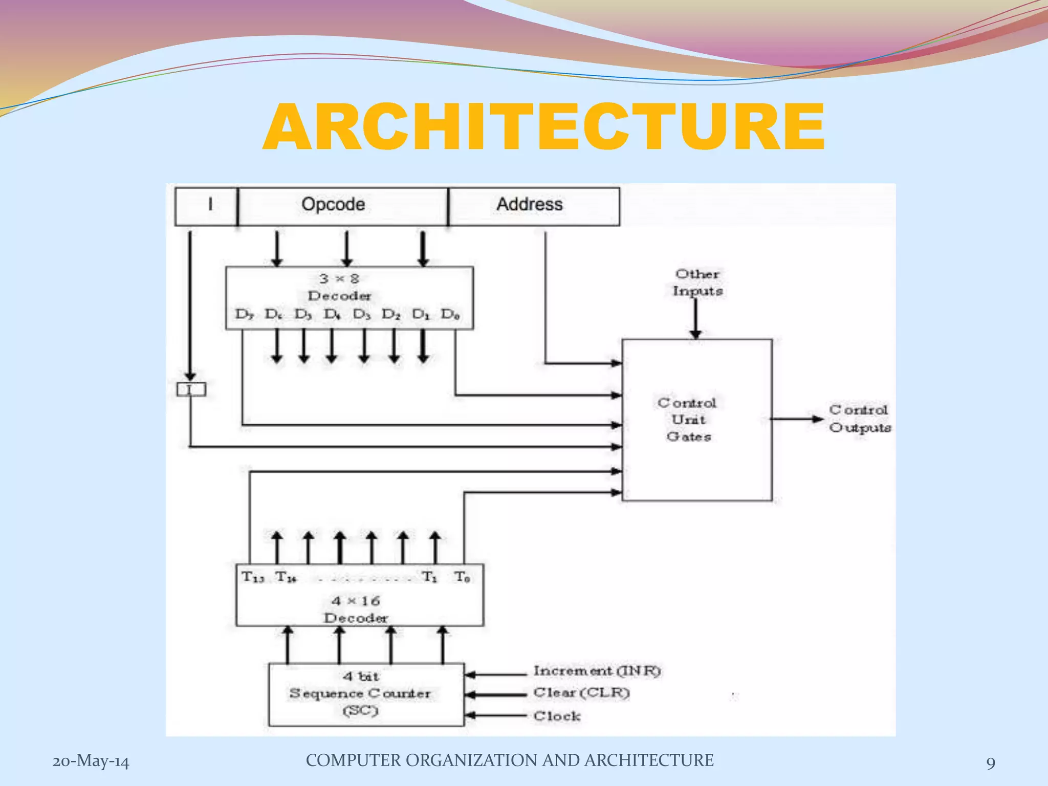
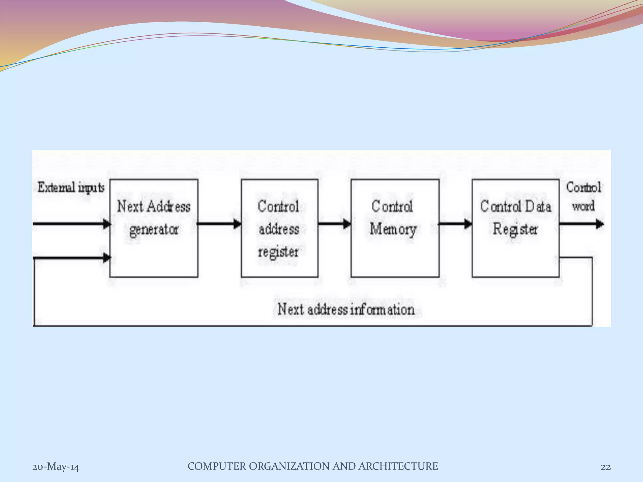
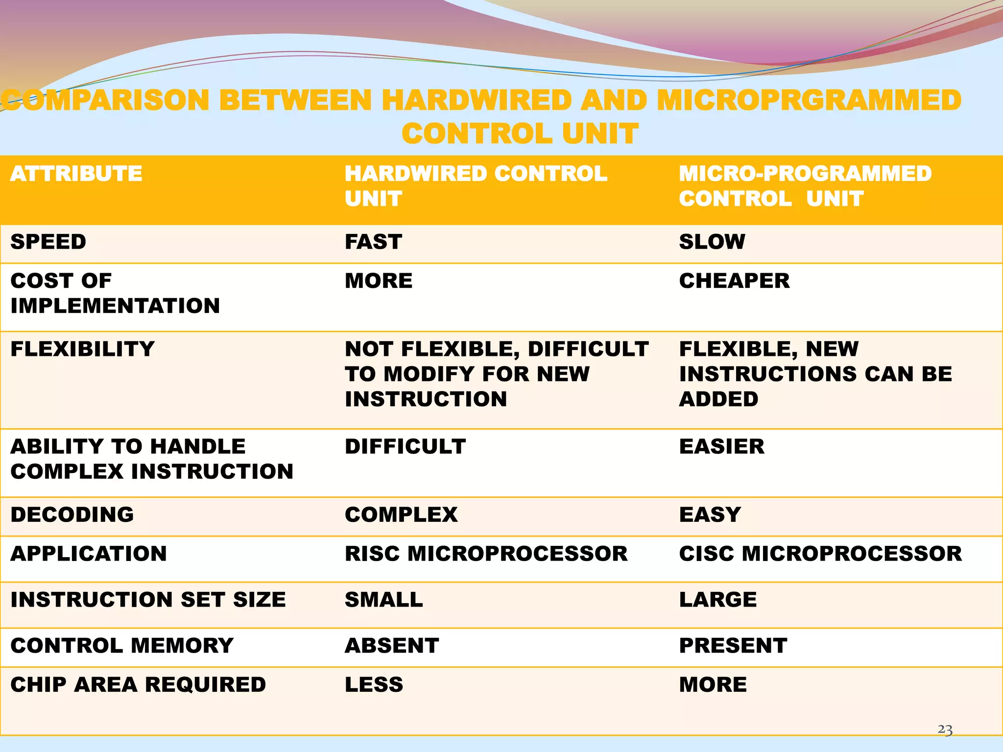
The control unit is responsible for controlling the flow of data and operations in a computer. It generates timing and control signals to coordinate the arithmetic logic unit, memory, and other components. Control units can be implemented using either hardwired or microprogrammed logic. A hardwired control unit uses combinational logic circuits like gates and flip-flops to directly generate control signals, while a microprogrammed control unit stores control sequences as microprograms in a control memory and executes them step-by-step using microinstructions. Both approaches have advantages and disadvantages related to speed, flexibility, cost, and complexity of implementation.
The main Objective of this presentation is to define computer buses , especially system bus . which is consists of data bus , address bus and control bus.
Introduction to Bus | Address, Data, Control BusHem Pokhrel
Handouts for BBa First Semester Prime College.
UNIT 5: Central Processing Unit: Control Unit, Arithmetic and Logic Unit, Register set, Functions of Central Processing Unit. Introduction to Bus (Address, Data, Control)
This slide provide the introduction to the computer , instruction formats and their execution, Common Bus System , Instruction Cycle, Hardwired Control Unit and I/O operation and handling of interrupt
CISC & RISC Architecture with contents
History Of CISC & RISC
Need Of CISC
CISC
CISC Characteristics
CISC Architecture
The Search for RISC
RISC Characteristics
Bus Architecture
Pipeline Architecture
Compiler Structure
Commercial Application
Reference
An arithmetic logic unit (ALU) is a digital electronic circuit that performs arithmetic and bitwise logical operations on integer binary numbers.
This is in contrast to a floating-point unit (FPU), which operates on floating point numbers. It is a fundamental building block of many types of computing circuits, including the central processing unit (CPU) of computers, FPUs, and graphics processing units.
A single CPU, FPU or GPU may contain multiple ALUs
History Of ALU:Mathematician John von Neumann proposed the ALU concept in 1945 in a report on the foundations for a new computer called the EDVAC(Electronic Discrete Variable Automatic Computer
Typical Schematic Symbol of an ALU:A and B: the inputs to the ALU
R: Output or Result
F: Code or Instruction from the
Control Unit
D: Output status; it indicates cases
Circuit operation:An ALU is a combinational logic circuit
Its outputs will change asynchronously in response to input changes
The external circuitry connected to the ALU is responsible for ensuring the stability of ALU input signals throughout the operation
In computing, an arithmetic logic unit (ALU) is a digital circuit that performs arithmetic and logical operations. The ALU is a fundamental building block of the central processing unit (CPU) of a computer, and even the simplest microprocessors contain one for purposes such as maintaining timers. The processors found inside modern CPUs and graphics processing units (GPUs) accommodate very powerful and very complex ALUs; a single component may contain a number of ALUs.
Training report prepared on PLC on CNC at BHEL,Hyderabad. It have sufficient slides to know the basics about PLC on CNC and working of that with coding. It was worth learning on BHEL.
International Journal of Computational Engineering Research(IJCER)ijceronline
International Journal of Computational Engineering Research(IJCER) is an intentional online Journal in English monthly publishing journal. This Journal publish original research work that contributes significantly to further the scientific knowledge in engineering and Technology.
Final Year Projects, Final Year Projects in Chennai, Software Projects, Embedded Projects, Microcontrollers Projects, DSP Projects, VLSI Projects, Matlab Projects, Java Projects, .NET Projects, IEEE Projects, IEEE 2009 Projects, IEEE 2009 Projects, Software, IEEE 2009 Projects, Embedded, Software IEEE 2009 Projects, Embedded IEEE 2009 Projects, Final Year Project Titles, Final Year Project Reports, Final Year Project Review, Robotics Projects, Mechanical Projects, Electrical Projects, Power Electronics Projects, Power System Projects, Model Projects, Java Projects, J2EE Projects, Engineering Projects, Student Projects, Engineering College Projects, MCA Projects, BE Projects, BTech Projects, ME Projects, MTech Projects, Wireless Networks Projects, Network Security Projects, Networking Projects, final year projects, ieee projects, student projects, college projects, ieee projects in chennai, java projects, software ieee projects, embedded ieee projects, "ieee2009projects", "final year projects", "ieee projects", "Engineering Projects", "Final Year Projects in Chennai", "Final year Projects at Chennai"
Students, digital devices and success - Andreas Schleicher - 27 May 2024..pptxEduSkills OECD
Andreas Schleicher presents at the OECD webinar ‘Digital devices in schools: detrimental distraction or secret to success?’ on 27 May 2024. The presentation was based on findings from PISA 2022 results and the webinar helped launch the PISA in Focus ‘Managing screen time: How to protect and equip students against distraction’ https://www.oecd-ilibrary.org/education/managing-screen-time_7c225af4-en and the OECD Education Policy Perspective ‘Students, digital devices and success’ can be found here - https://oe.cd/il/5yV
Instructions for Submissions thorugh G- Classroom.pptxJheel Barad
This presentation provides a briefing on how to upload submissions and documents in Google Classroom. It was prepared as part of an orientation for new Sainik School in-service teacher trainees. As a training officer, my goal is to ensure that you are comfortable and proficient with this essential tool for managing assignments and fostering student engagement.
Read| The latest issue of The Challenger is here! We are thrilled to announce that our school paper has qualified for the NATIONAL SCHOOLS PRESS CONFERENCE (NSPC) 2024. Thank you for your unwavering support and trust. Dive into the stories that made us stand out!
Unit 8 - Information and Communication Technology (Paper I).pdfThiyagu K
This slides describes the basic concepts of ICT, basics of Email, Emerging Technology and Digital Initiatives in Education. This presentations aligns with the UGC Paper I syllabus.
The Art Pastor's Guide to Sabbath | Steve ThomasonSteve Thomason
What is the purpose of the Sabbath Law in the Torah. It is interesting to compare how the context of the law shifts from Exodus to Deuteronomy. Who gets to rest, and why?
2024.06.01 Introducing a competency framework for languag learning materials ...Sandy Millin
http://sandymillin.wordpress.com/iateflwebinar2024
Published classroom materials form the basis of syllabuses, drive teacher professional development, and have a potentially huge influence on learners, teachers and education systems. All teachers also create their own materials, whether a few sentences on a blackboard, a highly-structured fully-realised online course, or anything in between. Despite this, the knowledge and skills needed to create effective language learning materials are rarely part of teacher training, and are mostly learnt by trial and error.
Knowledge and skills frameworks, generally called competency frameworks, for ELT teachers, trainers and managers have existed for a few years now. However, until I created one for my MA dissertation, there wasn’t one drawing together what we need to know and do to be able to effectively produce language learning materials.
This webinar will introduce you to my framework, highlighting the key competencies I identified from my research. It will also show how anybody involved in language teaching (any language, not just English!), teacher training, managing schools or developing language learning materials can benefit from using the framework.
2. The Control Unit was historically defined as one distinct part of the 1946
reference model of Von Neumann architecture.
The function of control unit is to generate relevant timing and control signals to
all operations in the computer.
Control Unit is “the brain within the brain”.
It controls the flow of data between the processor and memory and peripherals.
The examples of devices that require a control unit are CPUs and graphics
processing units (GPUs).
2COMPUTER ORGANIZATION AND ARCHITECTURE20-May-14
3. FUNCTIONS
The control unit directs the entire computer system to carry out stored
program instructions.
The control unit must communicate with both the arithmetic logic unit
(ALU) and main memory.
The control unit instructs the arithmetic logic unit that which logical or
arithmetic operation is to be performed.
The control unit co-ordinates the activities of the other two units as well
as all peripherals and auxiliary storage devices linked to the computer.
3COMPUTER ORGANIZATION AND ARCHITECTURE20-May-14
4. TYPES
Control unit generates control signals using one of the two
organizations :
Hardwired Control Unit.
Micro-programmed Control Unit.
4COMPUTER ORGANIZATION AND ARCHITECTURE20-May-14
5. Hardwired Control Unit
Hardwired control units are implemented through use of sequential
logic units or circuits like gates , fliflops , decoders in hardware.
Hardwired control units are generally faster than micro-programmed
designs.
This architecture is preferred in reduced instruction set computers (RISC)
as they use a simpler instruction set.
The hardwired approach has become less popular as computers have
evolved as at one time, control units for CPUs were ad-hoc logic, and they
were difficult to design.
5COMPUTER ORGANIZATION AND ARCHITECTURE20-May-14
6. ADVANTAGES
Hardwired Control Unit is fast because control signals are generated by
combinational circuits.
The delay in generation of control signals depends upon the number of
gates.
The performances is high as compared to micro-programmed control unit.
6COMPUTER ORGANIZATION AND ARCHITECTURE20-May-14
7. DISADVANTAGES
The control signals required by the CPU will be more complex
Modifications in control signal are very difficult. That means it requires
rearranging of wires in the hardware circuit.
It is difficult to correct mistake in original design or adding new features
in existing design of control unit.
7COMPUTER ORGANIZATION AND ARCHITECTURE20-May-14
8. CONSIST OF:
Control unit consist of a:
Instruction Register
Number of Control Logic Gates,
Two Decoders
4-bit Sequence Counter
8COMPUTER ORGANIZATION AND ARCHITECTURE20-May-14
10. An instruction read from memory is placed in the instruction register (IR).
The instruction register is divided into three parts: the I bit, operation
code, and address part.
First 12-bits (0-11) to specify an address, next 3-bits specify the
operation code (opcode) field of the instruction and last left most bit
specify the addressing mode I.
I = 0 for direct address
I = 1 for indirect address
10COMPUTER ORGANIZATION AND ARCHITECTURE20-May-14
11. First 12-bits (0-11) are applied to the control logic gates.
The operation code bits (12 – 14) are decoded with a 3 x 8 decoder.
The eight outputs ( D0 through D7) from a decoder goes to the control
logic gates to perform specific operation.
Last bit 15 is transferred to a I flip-flop designated by symbol I.
11COMPUTER ORGANIZATION AND ARCHITECTURE20-May-14
12. The 4-bit sequence counter SC can count in binary from 0 through 15.
The counter output is decoded into 16 timing pulses T0 through T15.
The sequence counter can be incremented by INR.
input or clear by CLR input synchronously.
12COMPUTER ORGANIZATION AND ARCHITECTURE20-May-14
13. EXAMPLE
Consider the case where SC is incremented to provide timing signalsT0,
T1, T 2 , T3, and T4 in sequence. At time T4 , SC is cleared to 0 if decoder
output D3 is active. This is expressed symbolically by the statement:
D3 T4 : SC ← 0
The timing diagram shows the time relationship of the control signals.
13COMPUTER ORGANIZATION AND ARCHITECTURE20-May-14
15. MICRO-PROGRAMMED
CONTROL UNIT
The idea of microprogramming was introduced by Maurice Wilkes in 1951.
Micro-programs were organized as a sequence of microinstructions and
stored in special control memory.
The main advantage of the micro-program control unit is the simplicity of
its structure.
Outputs of the controller are organized in microinstructions and they can
be easily replaced
15COMPUTER ORGANIZATION AND ARCHITECTURE20-May-14
16. A micro-programmed control unit is implemented using programming
approach. A sequence of micro operations are carried out by executing a
program consisting of micro-instructions.
Micro-program, consisting of micro-instructions is stored in the control
memory of the control unit.
Execution of a micro-instruction is responsible for generation of a set of
control signals.
16COMPUTER ORGANIZATION AND ARCHITECTURE20-May-14
17. Micro-Programs: Microprogramming is the concept for generating
control signals using programs. These programs are called micro -
programs.
Micro-Instructions: The instructions that make micro-program are called
micro-instructions.
Micro-Code: Micro-program is a group of microinstructions. The micro-
program can also be termed as micro-code.
Control Memory: Micro-programs are stored in the read only memory
(ROM). That memory is called control memory.
17COMPUTER ORGANIZATION AND ARCHITECTURE20-May-14
18. ADVANTAGES
The design of micro-program control unit is less complex because micro-
programs are implemented using software routines.
The micro-programmed control unit is more flexible because design
modifications, correction and enhancement is easily possible.
The new or modified instruction set of CPU can be easily implemented by
simply rewriting or modifying the contents of control memory.
The fault can be easily diagnosed in the micro-program control unit using
diagnostics tools by maintaining the contents of flags, registers and
counters.
18COMPUTER ORGANIZATION AND ARCHITECTURE20-May-14
19. DISADVANTAGES
The micro-program control unit is slower than hardwired control unit.
That means to execute an instruction in micro-program control unit
requires more time.
The micro-program control unit is expensive than hardwired control unit
in case of limited hardware resources.
The design duration of micro-program control unit is more than hardwired
control unit for smaller CPU.
19COMPUTER ORGANIZATION AND ARCHITECTURE20-May-14
20. 20-May-14 20
CONSIST OF :
Control unit consist of a :
Next address generator
Control address register
Control memory
Control data register
COMPUTER ORGANIZATION AND ARCHITECTURE
21. ARCHITECTURE
The address of micro-instruction that is to be executed is stored in the
control address register (CAR).
Micro-instruction corresponding to the address stored in CAR is fetched
from control memory and is stored in the control data register (CDR).
This micro-instruction contains control word to execute one or more
micro-operations.
After the execution of all micro-operations of micro-instruction, the
address of next micro-instruction is located.
21COMPUTER ORGANIZATION AND ARCHITECTURE20-May-14
23. COMPARISON BETWEEN HARDWIRED AND MICROPRGRAMMED
CONTROL UNIT
ATTRIBUTE HARDWIRED CONTROL
UNIT
MICRO-PROGRAMMED
CONTROL UNIT
SPEED FAST SLOW
COST OF
IMPLEMENTATION
MORE CHEAPER
FLEXIBILITY NOT FLEXIBLE, DIFFICULT
TO MODIFY FOR NEW
INSTRUCTION
FLEXIBLE, NEW
INSTRUCTIONS CAN BE
ADDED
ABILITY TO HANDLE
COMPLEX INSTRUCTION
DIFFICULT EASIER
DECODING COMPLEX EASY
APPLICATION RISC MICROPROCESSOR CISC MICROPROCESSOR
INSTRUCTION SET SIZE SMALL LARGE
CONTROL MEMORY ABSENT PRESENT
CHIP AREA REQUIRED LESS MORE
23