Downloaded 161 times

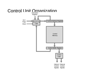
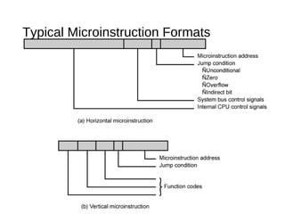

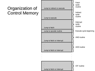


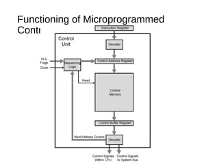
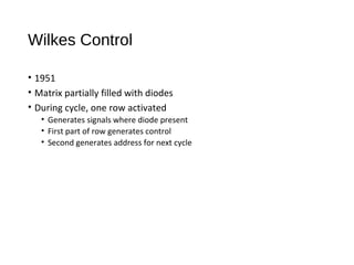


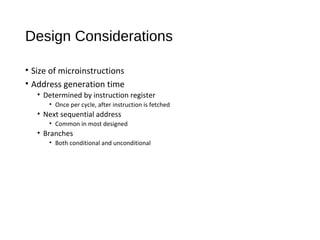
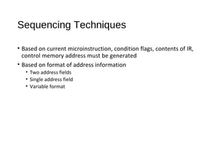


This document discusses the organization and functioning of micro-programmed control units within microprocessors, highlighting the generation of control signals and the various encoding techniques for micro-instructions. It contrasts vertical and horizontal micro-programming, explaining their respective advantages and limitations in parallelism and complexity. The document also addresses design considerations, microinstruction formats, and improvements over early control unit designs.