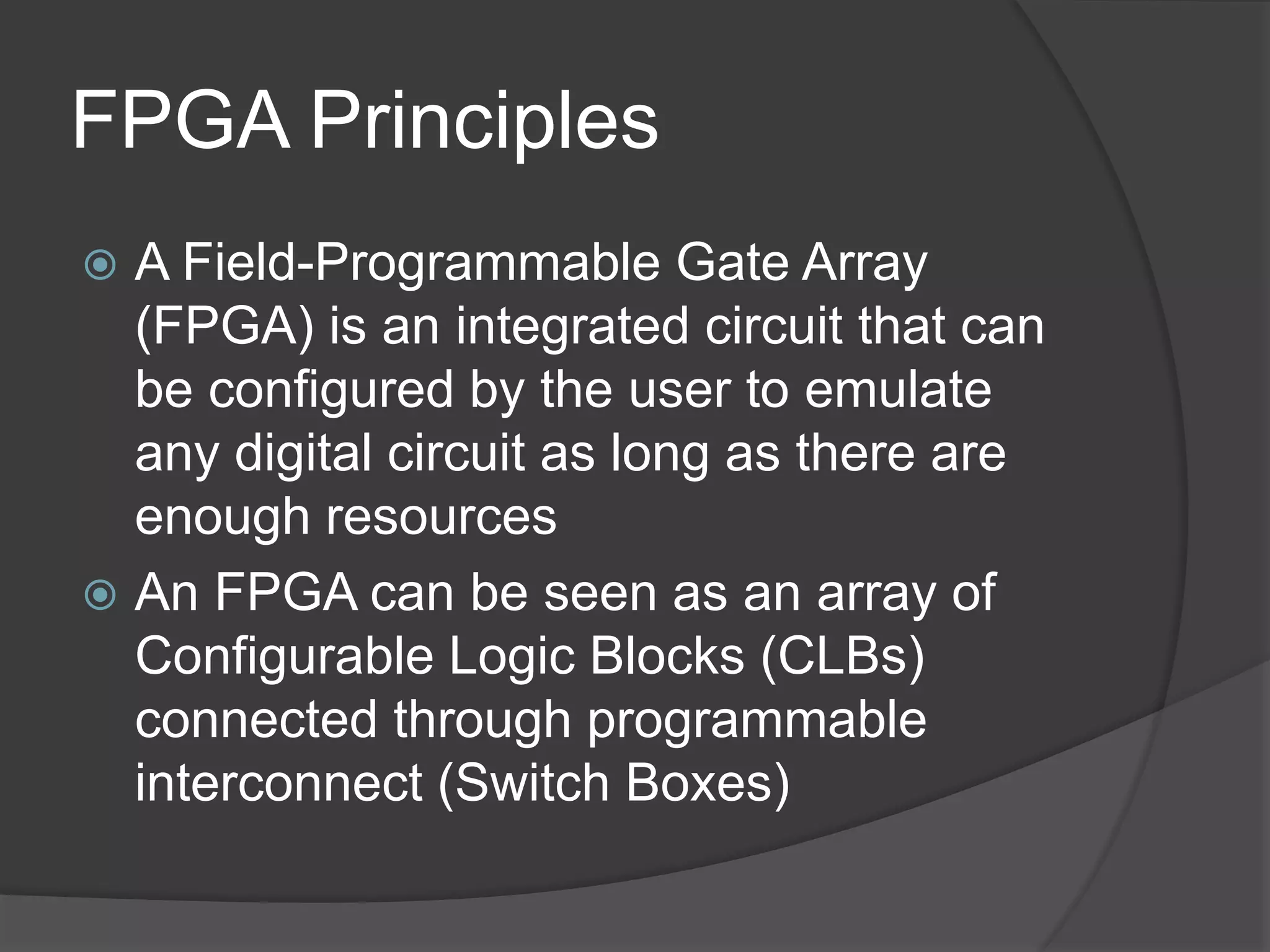
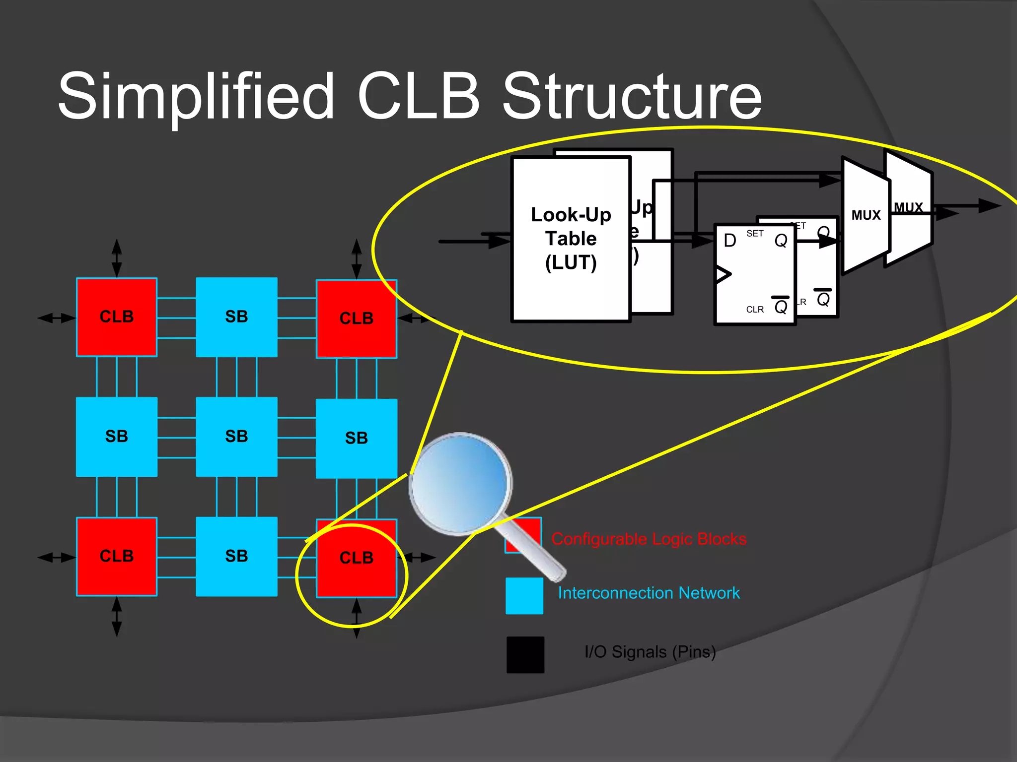
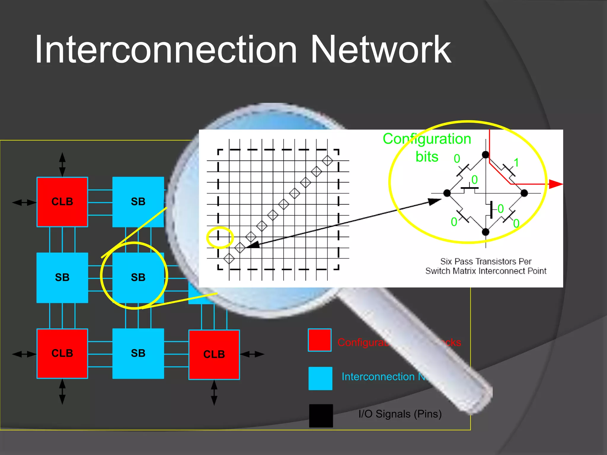
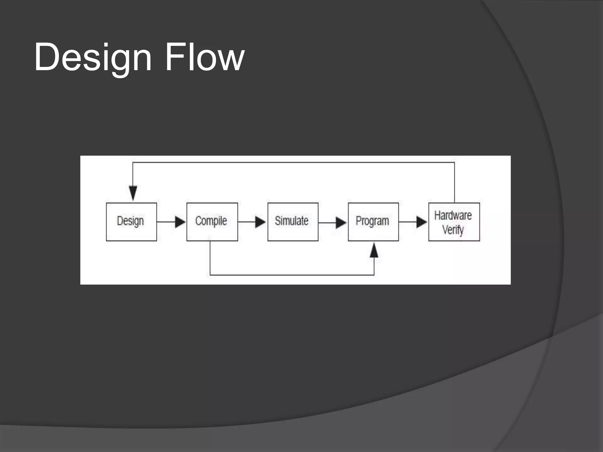
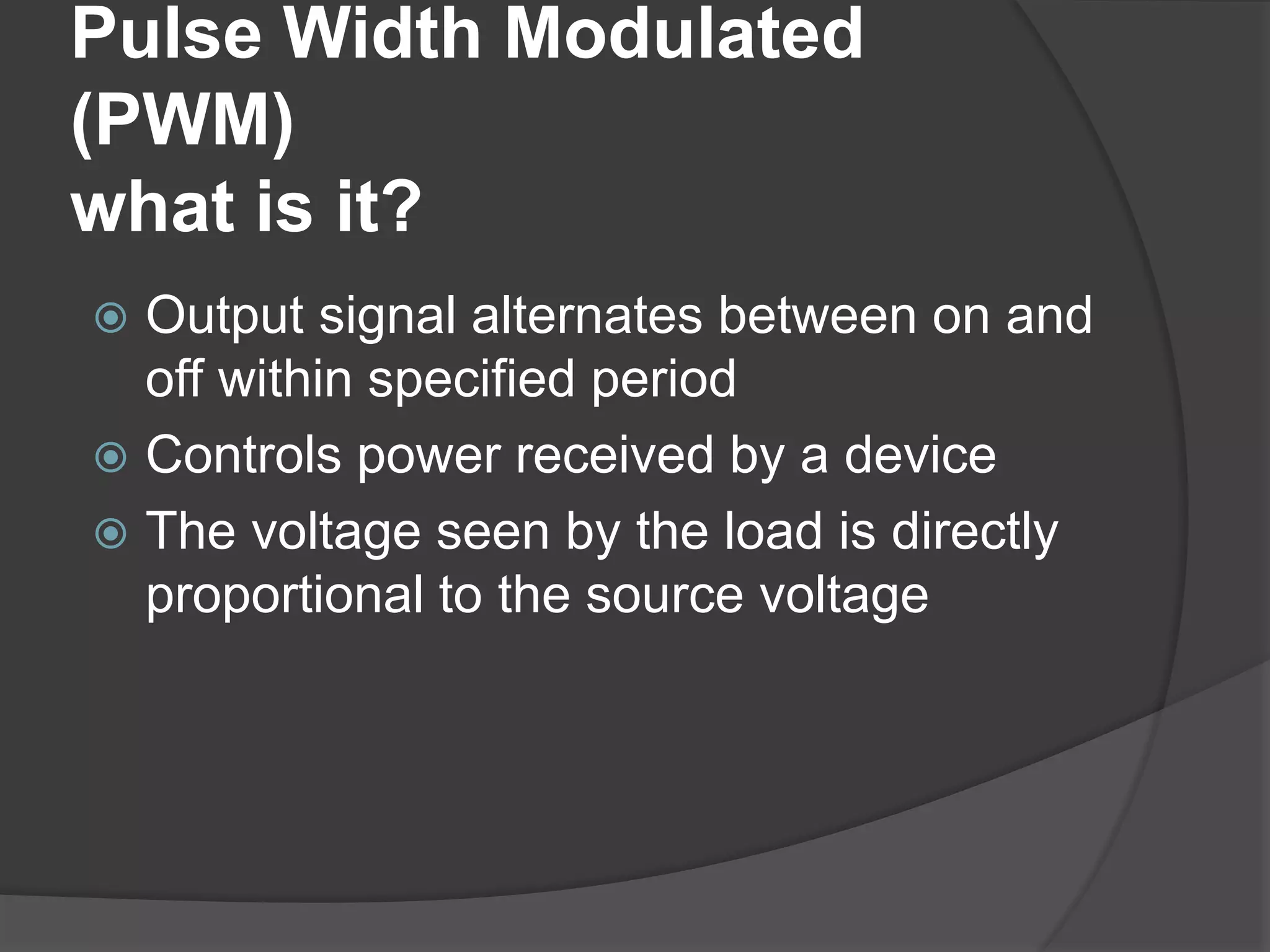
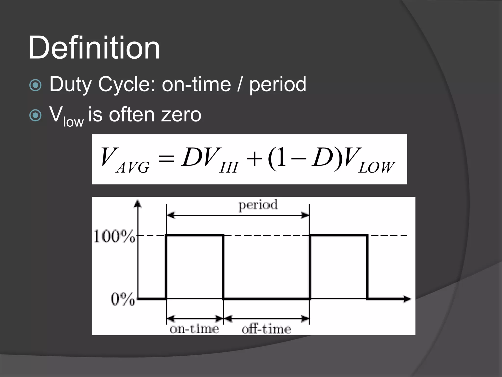
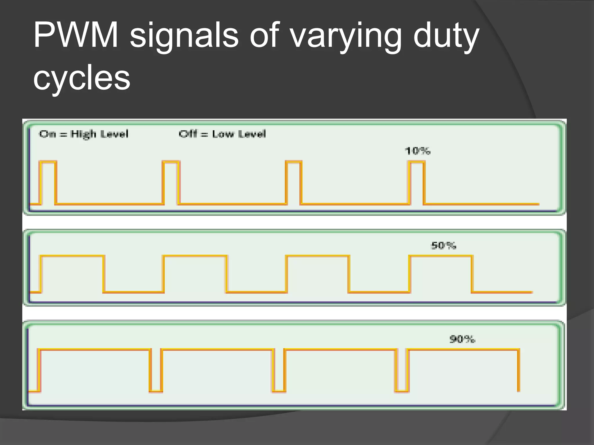
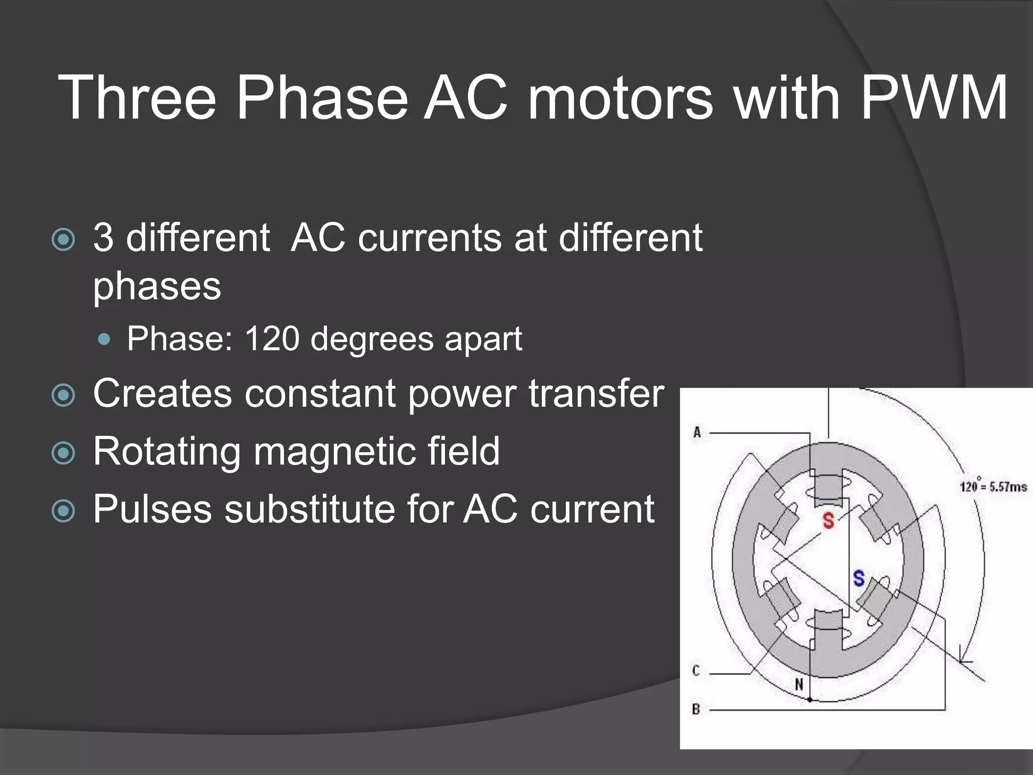
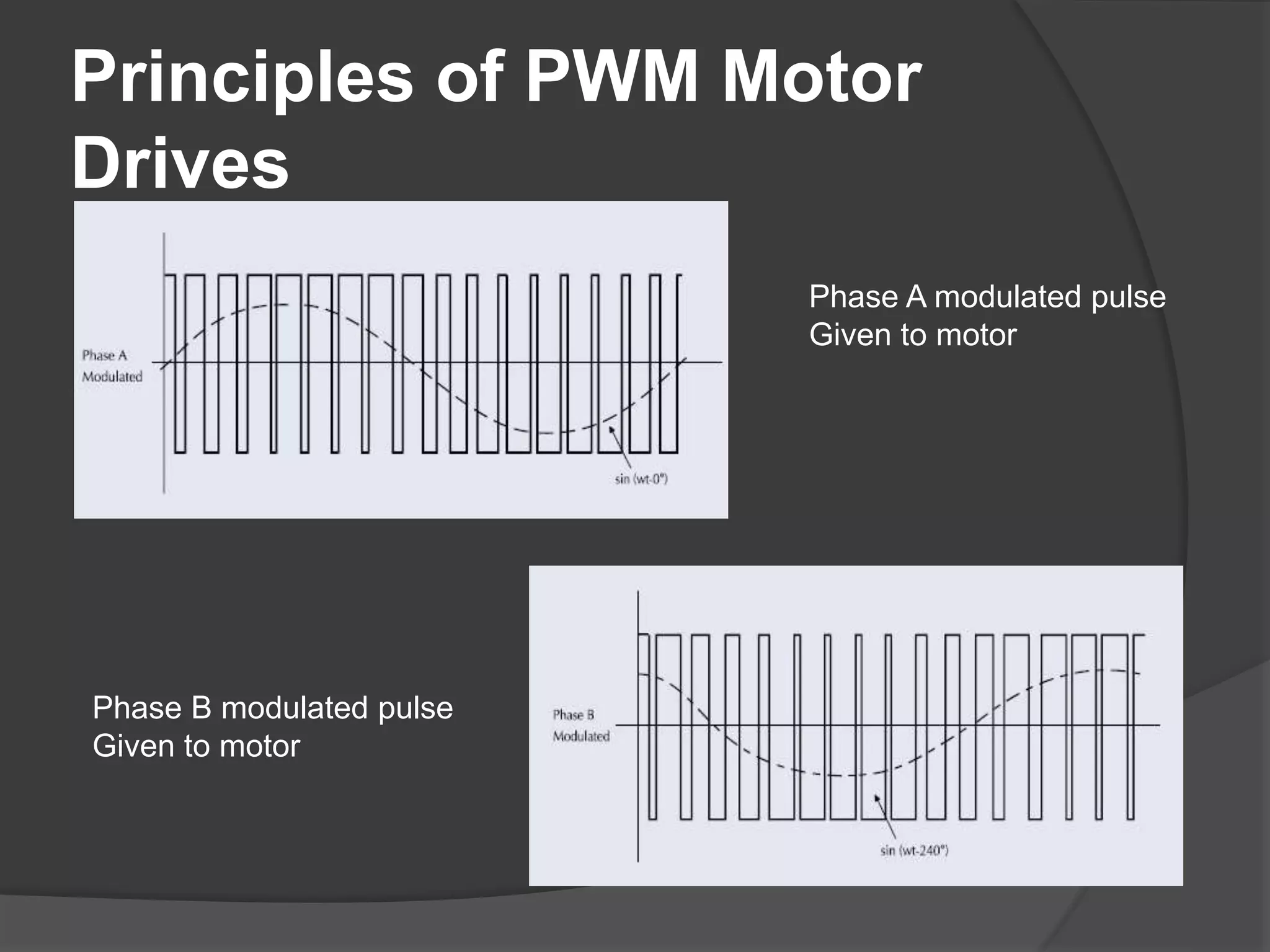
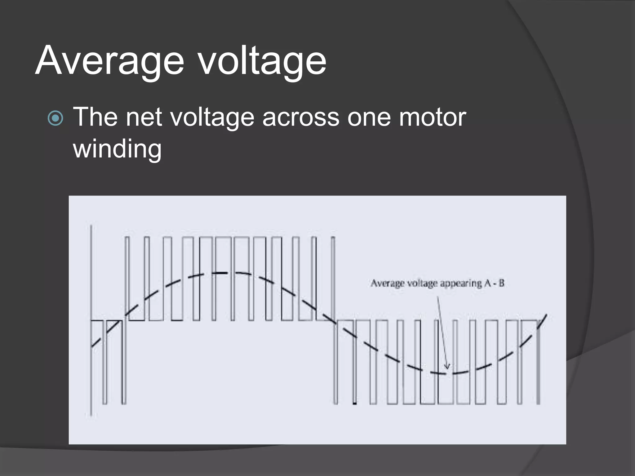
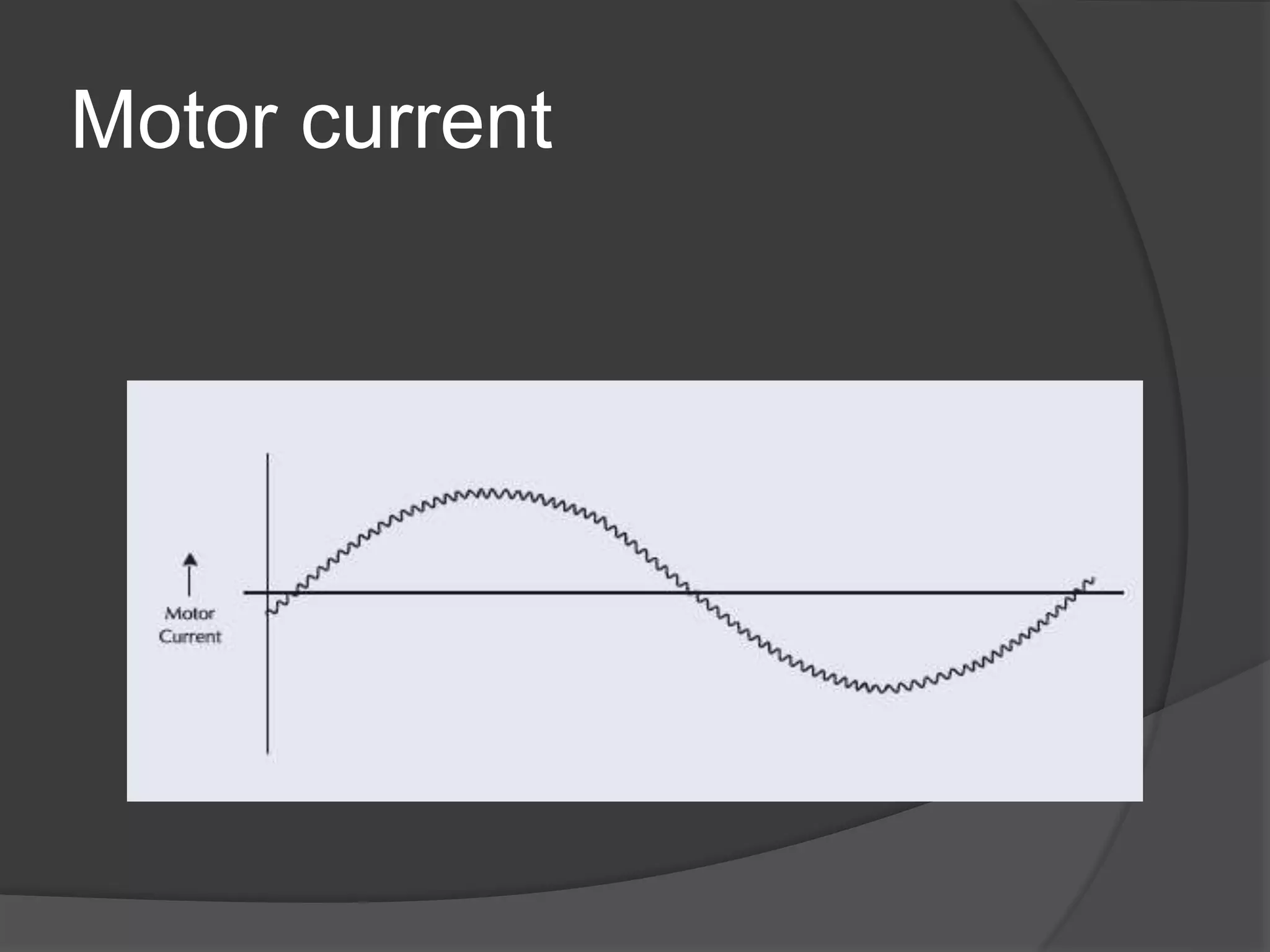
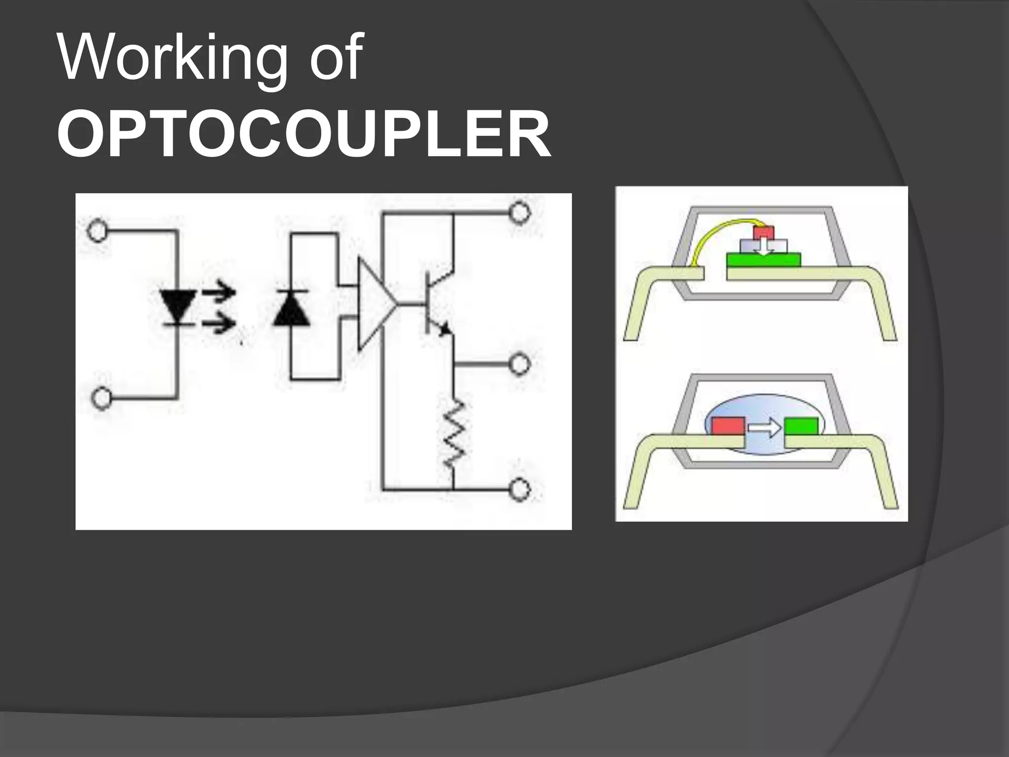
A
Seminar
On
“FPGA BASED MOTOR
CONTROLLER”
Introduction
 The recent advances in FPGA (Field
Programmable Gate Array) technology have made
it possible to implement digital control algorithms
in hardware solution with low costs.
FPGA In motor control
 FPGA are being more popular in motor
control
 Wide integration capabilities
 Higher performance, reduce latency
 Cost reduction
FPGA Principles
 A Field-Programmable Gate Array
(FPGA) is an integrated circuit that can
be configured by the user to emulate
any digital circuit as long as there are
enough resources
 An FPGA can be seen as an array of
Configurable Logic Blocks (CLBs)
connected through programmable
interconnect (Switch Boxes)
FPGA-Xilinx Spartan-3E Starter
Kit
FPGA
buttons
switches
LEDs
FPGA structure
CLB SB
SB SB
CLB
SB
CLB SB CLB
Configurable Logic Blocks
Interconnection Network
I/O Signals (Pins)
Simplified CLB Structure
CLB SB
SB SB
CLB
SB
CLB SB CLB
Configurable Logic Blocks
Interconnection Network
I/O Signals (Pins)
Look-Up
Table
(LUT)
Q
Q
SET
CLR
D
MUX
Look-Up
Table
(LUT)
Q
Q
SET
CLR
D
MUX
CLB SB
SB SB
CLB
SB
CLB SB CLB
Configurable Logic Blocks
Interconnection Network
I/O Signals (Pins)
Configuration
bits 1
0
0
0
0
0
Interconnection Network
Design Flow
Pulse Width Modulated
(PWM)
what is it?
 Output signal alternates between on and
off within specified period
 Controls power received by a device
 The voltage seen by the load is directly
proportional to the source voltage
Definition
LOWHIAVG VDDVV )1( 
 Duty Cycle: on-time / period
 Vlow is often zero
PWM signals of varying duty
cycles
Three Phase AC motors with PWM
 3 different AC currents at different
phases
 Phase: 120 degrees apart
 Creates constant power transfer
 Rotating magnetic field
 Pulses substitute for AC current
Principles of PWM Motor
Drives
Phase A modulated pulse
Given to motor
Phase B modulated pulse
Given to motor
Average voltage
 The net voltage across one motor
winding
Motor current
OPTOCOUPLER
 An opto-isolator, also called an optocoupler,
photocoupler, or optical isolator, is a
component that transfers electrical signals
between two isolated circuits by using light.
 Opto-isolators prevent high voltages from
affecting the system receiving the signal.
 Commercially available opto-isolators
withstand input-to-output voltages up to 10 Kv
and voltage transients with speeds up to 10
kV/μs.
Working of
OPTOCOUPLER
ADVANTAGES
 High motor efficiency
 Fast control response
 Lower motor torque ripple
 Close to ideal sinusoidal motor current
waveform
CONCLUSION
 By controlling the amplitude and
frequency of the modulating waveforms,
the PWM drive can output to the motor a
three phase supply with the use of
optocoupler at the necessary voltage
and frequency to drive the motor at any
required speed.
Fpga based motor controller

Fpga based motor controller

  • 1.
  • 2.
    Introduction  The recentadvances in FPGA (Field Programmable Gate Array) technology have made it possible to implement digital control algorithms in hardware solution with low costs.
  • 3.
    FPGA In motorcontrol  FPGA are being more popular in motor control  Wide integration capabilities  Higher performance, reduce latency  Cost reduction
  • 4.
    FPGA Principles  AField-Programmable Gate Array (FPGA) is an integrated circuit that can be configured by the user to emulate any digital circuit as long as there are enough resources  An FPGA can be seen as an array of Configurable Logic Blocks (CLBs) connected through programmable interconnect (Switch Boxes)
  • 5.
  • 6.
    FPGA structure CLB SB SBSB CLB SB CLB SB CLB Configurable Logic Blocks Interconnection Network I/O Signals (Pins)
  • 7.
    Simplified CLB Structure CLBSB SB SB CLB SB CLB SB CLB Configurable Logic Blocks Interconnection Network I/O Signals (Pins) Look-Up Table (LUT) Q Q SET CLR D MUX Look-Up Table (LUT) Q Q SET CLR D MUX
  • 8.
    CLB SB SB SB CLB SB CLBSB CLB Configurable Logic Blocks Interconnection Network I/O Signals (Pins) Configuration bits 1 0 0 0 0 0 Interconnection Network
  • 9.
  • 10.
    Pulse Width Modulated (PWM) whatis it?  Output signal alternates between on and off within specified period  Controls power received by a device  The voltage seen by the load is directly proportional to the source voltage
  • 11.
    Definition LOWHIAVG VDDVV )1(  Duty Cycle: on-time / period  Vlow is often zero
  • 12.
    PWM signals ofvarying duty cycles
  • 13.
    Three Phase ACmotors with PWM  3 different AC currents at different phases  Phase: 120 degrees apart  Creates constant power transfer  Rotating magnetic field  Pulses substitute for AC current
  • 14.
    Principles of PWMMotor Drives Phase A modulated pulse Given to motor Phase B modulated pulse Given to motor
  • 15.
    Average voltage  Thenet voltage across one motor winding
  • 16.
  • 17.
    OPTOCOUPLER  An opto-isolator,also called an optocoupler, photocoupler, or optical isolator, is a component that transfers electrical signals between two isolated circuits by using light.  Opto-isolators prevent high voltages from affecting the system receiving the signal.  Commercially available opto-isolators withstand input-to-output voltages up to 10 Kv and voltage transients with speeds up to 10 kV/μs.
  • 18.
  • 19.
    ADVANTAGES  High motorefficiency  Fast control response  Lower motor torque ripple  Close to ideal sinusoidal motor current waveform
  • 20.
    CONCLUSION  By controllingthe amplitude and frequency of the modulating waveforms, the PWM drive can output to the motor a three phase supply with the use of optocoupler at the necessary voltage and frequency to drive the motor at any required speed.