Downloaded 1,198 times


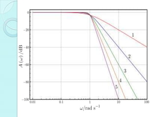


A filter is an electrical network that transmits signals within a specified frequency range called the pass band, and suppresses signals in the stop band, separated by the cut-off frequency. Digital filters are used to eliminate noise and extract signals of interest, implemented using software rather than RLC components. Digital filters are FIR (finite impulse response) or IIR (infinite impulse response) depending on the number of sample points used. An ideal filter would transmit signals in the pass band without attenuation and completely suppress the stop band, but ideal filters cannot be realized. IIR filter design first develops an analog IIR filter, then converts it to digital using methods like impulse invariant, approximation of derivatives, or bilinear transformation.