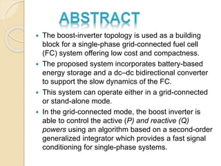
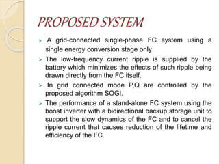
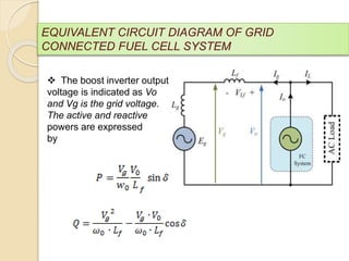
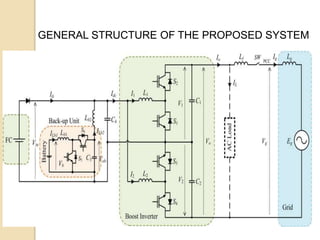
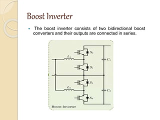
Presented By
S.ROHITHA - 1075036
M.SAI KIRANMAI - 1075037
S.SARALA - 1075039
Under the guidance of
M.PALLAVI, M.TECH
SRI PADMAVATI MAHILA VISVAVIDYALAYAM
Head of the Department
Prof. C. ESWAR REDDY
M.TECH,PHD,FIE
 The boost-inverter topology is used as a building
block for a single-phase grid-connected fuel cell
(FC) system offering low cost and compactness.
 The proposed system incorporates battery-based
energy storage and a dc–dc bidirectional converter
to support the slow dynamics of the FC.
 This system can operate either in a grid-connected
or stand-alone mode.
 In the grid-connected mode, the boost inverter is
able to control the active (P) and reactive (Q)
powers using an algorithm based on a second-order
generalized integrator which provides a fast signal
conditioning for single-phase systems.
EXISTING SYSTEM
 Fuel cell based power supply system needs
a power conditioner to convert the low dc
output voltage generated by the fuel cell into
usable ac voltage for any practical
application.
 Traditional two-stage power conditioner
architecture consists of an active clamp full-
bridge boost converter (ACFBC) for the dc-
dc stage and a full-bridge sinusoidal pulse
width modulation (SPWM) inverter for dc-ac
stage.
EXISTING SYSTEM DRAWBACKS
 Bulky
 Costly
 Relatively inefficient
PROPOSED SYSTEM
 A grid-connected single-phase FC system using a
single energy conversion stage only.
 The low-frequency current ripple is supplied by the
battery which minimizes the effects of such ripple being
drawn directly from the FC itself.
 In grid connected mode P,Q are controlled by the
proposed algorithm SOGI.
 The performance of a stand-alone FC system using the
boost inverter with a bidirectional backup storage unit to
support the slow dynamics of the FC and to cancel the
ripple current that causes reduction of the lifetime and
efficiency of the FC.
The proposed FC system includes
 Fuel Cell system
 Boost Inverter
 Backup energy storage unit
 Control of the Grid Connected Boost Inverter
BLOCK DIAGRAM
EQUIVALENT CIRCUIT DIAGRAM OF GRID
CONNECTED FUEL CELL SYSTEM
 The boost inverter output
voltage is indicated as Vo
and Vg is the grid voltage.
The active and reactive
powers are expressed
by
GENERAL STRUCTURE OF THE PROPOSED SYSTEM
Fuel Cell
 Electrons are drawn from the anode to the
cathode through an external circuit,
producing direct current electricity.
 As the main difference among fuel cell
types is the electrolyte, fuel cells are
classified by the type of electrolyte they use
followed by the difference in startup time
ranging from 1 sec for PEMFC to 10 min for
SOFC
Operation Of A Fuel Cell
Types Of Fuel Cells
 Proton exchange membrane fuel cells
(PEMFCs)
 Phosphoric acid fuel cell (PAFC)
 High-temperature fuel cells
 SOFC
 MCFC
PEMFC
Applications
• Power
• Fuel cell electric vehicles (FCEVs)
 Automobiles
 Buses
 Forklifts
 Motorcycles and bicycles
 Airplanes
 Boats
 Submarines
Boost Inverter
 The boost inverter consists of two bidirectional boost
converters and their outputs are connected in series.
Boost inverter(contd…)
 A double-loop control scheme is
chosen for the boost-inverter control
being the most appropriate method to
control the individual boost converters
covering the wide range of operating
points.
Backup Energy Storage Unit
 The functions of the backup energy storage
unit are divided into two parts.
 First, the backup unit is designed to support
the slow dynamics of the FC.
 Second, in order to protect the FC system,
the backup unit provides low-frequency ac
current that is required from the boost
inverter operation.
 The backup unit comprises of a current-
mode controlled bidirectional converter
and a battery as the energy storage unit.
Simulation Block Diagram
Simulation Results
Output Voltages Of Boost Inverter
V1 V2 V0
Output at AC Grid
Ig
Vg
Input Current Of Boost Inverter
I0
ADVANTAGES
 Low cost
 Compactness
 High power conversion efficiency
 Reduced converter size
 Able to operate in stand-alone as well as in
grid-connected mode
Conclusion
 The proposed FC system has a number of attractive
features, such as single power conversion stage with
high efficiency, simplified topology, low cost, and
able to operate in stand-alone as well as in grid-
connected mode.
 In the grid-connected mode, the single-phase FC
system is able to control the active and reactive
powers by a PQ control algorithm based on SOGI
which offers a fast signal conditioning for single-
phase systems.
 It should be noted that the voltage-mode control
adopted for the boost inverter may result in a
distorted grid current (under given THD) if the grid
voltage includes a harmonic component.
REFERENCES
1. S. B. Kjaer, J. K. Pedersen, and F. Blaabjerg,
“A review of single-phase grid-connected
inverters for photovoltaic modules,” IEEE
Trans. Ind. Appl., vol. 41, no. 5, pp. 1292–
1306, Sep./Oct. 2005.
2. J.-S. Lai, “Power conditioning circuit
topologies,” IEEE Ind. Electron. Mag., vol. 3,
no. 2, pp. 24–34, Jun. 2009.
3. Horizon Fuel Cell Technologies, H-Series
PEMFC System User Guide(2010). [Online].
Available: http://www.horizonfuelcell.com
Single phase grid connected fuel system based on boost inverter

Single phase grid connected fuel system based on boost inverter

  • 1.
    Presented By S.ROHITHA -1075036 M.SAI KIRANMAI - 1075037 S.SARALA - 1075039 Under the guidance of M.PALLAVI, M.TECH SRI PADMAVATI MAHILA VISVAVIDYALAYAM Head of the Department Prof. C. ESWAR REDDY M.TECH,PHD,FIE
  • 2.
     The boost-invertertopology is used as a building block for a single-phase grid-connected fuel cell (FC) system offering low cost and compactness.  The proposed system incorporates battery-based energy storage and a dc–dc bidirectional converter to support the slow dynamics of the FC.  This system can operate either in a grid-connected or stand-alone mode.  In the grid-connected mode, the boost inverter is able to control the active (P) and reactive (Q) powers using an algorithm based on a second-order generalized integrator which provides a fast signal conditioning for single-phase systems.
  • 3.
    EXISTING SYSTEM  Fuelcell based power supply system needs a power conditioner to convert the low dc output voltage generated by the fuel cell into usable ac voltage for any practical application.  Traditional two-stage power conditioner architecture consists of an active clamp full- bridge boost converter (ACFBC) for the dc- dc stage and a full-bridge sinusoidal pulse width modulation (SPWM) inverter for dc-ac stage.
  • 4.
    EXISTING SYSTEM DRAWBACKS Bulky  Costly  Relatively inefficient
  • 5.
    PROPOSED SYSTEM  Agrid-connected single-phase FC system using a single energy conversion stage only.  The low-frequency current ripple is supplied by the battery which minimizes the effects of such ripple being drawn directly from the FC itself.  In grid connected mode P,Q are controlled by the proposed algorithm SOGI.  The performance of a stand-alone FC system using the boost inverter with a bidirectional backup storage unit to support the slow dynamics of the FC and to cancel the ripple current that causes reduction of the lifetime and efficiency of the FC.
  • 6.
    The proposed FCsystem includes  Fuel Cell system  Boost Inverter  Backup energy storage unit  Control of the Grid Connected Boost Inverter
  • 7.
  • 8.
    EQUIVALENT CIRCUIT DIAGRAMOF GRID CONNECTED FUEL CELL SYSTEM  The boost inverter output voltage is indicated as Vo and Vg is the grid voltage. The active and reactive powers are expressed by
  • 9.
    GENERAL STRUCTURE OFTHE PROPOSED SYSTEM
  • 10.
    Fuel Cell  Electronsare drawn from the anode to the cathode through an external circuit, producing direct current electricity.  As the main difference among fuel cell types is the electrolyte, fuel cells are classified by the type of electrolyte they use followed by the difference in startup time ranging from 1 sec for PEMFC to 10 min for SOFC
  • 11.
    Operation Of AFuel Cell
  • 12.
    Types Of FuelCells  Proton exchange membrane fuel cells (PEMFCs)  Phosphoric acid fuel cell (PAFC)  High-temperature fuel cells  SOFC  MCFC
  • 13.
  • 14.
    Applications • Power • Fuelcell electric vehicles (FCEVs)  Automobiles  Buses  Forklifts  Motorcycles and bicycles  Airplanes  Boats  Submarines
  • 15.
    Boost Inverter  Theboost inverter consists of two bidirectional boost converters and their outputs are connected in series.
  • 16.
    Boost inverter(contd…)  Adouble-loop control scheme is chosen for the boost-inverter control being the most appropriate method to control the individual boost converters covering the wide range of operating points.
  • 17.
    Backup Energy StorageUnit  The functions of the backup energy storage unit are divided into two parts.  First, the backup unit is designed to support the slow dynamics of the FC.  Second, in order to protect the FC system, the backup unit provides low-frequency ac current that is required from the boost inverter operation.
  • 18.
     The backupunit comprises of a current- mode controlled bidirectional converter and a battery as the energy storage unit.
  • 19.
  • 20.
    Simulation Results Output VoltagesOf Boost Inverter V1 V2 V0
  • 21.
    Output at ACGrid Ig Vg
  • 22.
    Input Current OfBoost Inverter I0
  • 23.
    ADVANTAGES  Low cost Compactness  High power conversion efficiency  Reduced converter size  Able to operate in stand-alone as well as in grid-connected mode
  • 24.
    Conclusion  The proposedFC system has a number of attractive features, such as single power conversion stage with high efficiency, simplified topology, low cost, and able to operate in stand-alone as well as in grid- connected mode.  In the grid-connected mode, the single-phase FC system is able to control the active and reactive powers by a PQ control algorithm based on SOGI which offers a fast signal conditioning for single- phase systems.  It should be noted that the voltage-mode control adopted for the boost inverter may result in a distorted grid current (under given THD) if the grid voltage includes a harmonic component.
  • 25.
    REFERENCES 1. S. B.Kjaer, J. K. Pedersen, and F. Blaabjerg, “A review of single-phase grid-connected inverters for photovoltaic modules,” IEEE Trans. Ind. Appl., vol. 41, no. 5, pp. 1292– 1306, Sep./Oct. 2005. 2. J.-S. Lai, “Power conditioning circuit topologies,” IEEE Ind. Electron. Mag., vol. 3, no. 2, pp. 24–34, Jun. 2009. 3. Horizon Fuel Cell Technologies, H-Series PEMFC System User Guide(2010). [Online]. Available: http://www.horizonfuelcell.com