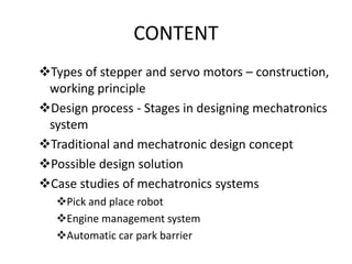
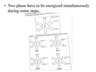
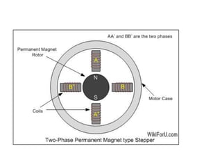
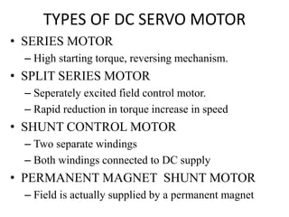
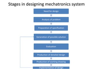
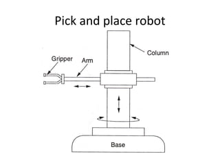
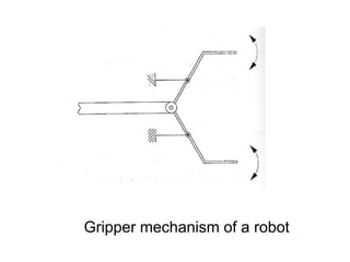
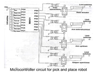
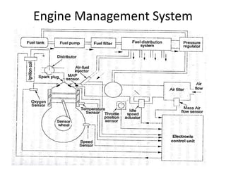
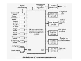
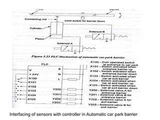
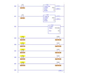
UNIT 5
ACTUATORS AND MECHATRONICS
SYSTEMS DESIGN
CONTENT
Types of stepper and servo motors – construction,
working principle
Design process - Stages in designing mechatronics
system
Traditional and mechatronic design concept
Possible design solution
Case studies of mechatronics systems
Pick and place robot
Engine management system
Automatic car park barrier
DC MOTORS
• DC motor used in large number of
Mechatronics design.
• Torqe speed characteristica achieveble
• PRINCIPLE:
– When a current carrying conductor is placed in a
magnetic field, it experiences a force.
– When conductor moves in a magnetic field E.M.F
is induced.
D.C motor principle
VARIABLE TYPES OF DC MOTOR
Types of DC motor
• PERMANENT MAGNET MOTOR
– Permanent magnet is high
– Reverse switching takes place
– Position and speed control application
• SERIES MOTOR
– Windings in series so starting torques
– High variable speed
• SHUNT MOTOR
– Constant speed over a large range of loading
– Lowest torque, good speed of regulation
Types of DC motor
• COMPOUND MOTOR
– Combined characteristics of both series and shunt
motor.
– High starting torque and speed regulation(stability).
• SEPARATE WOUND MOTOR
– It is the special case of shunt motor.
– Separate control of armature and field windings.
AC INDUCTION MOTOR
• Main parts of AC induction motor are ROTOR
(Rotating element) and STATOR (Stationary
element)
• Rotor construction look like squirrel cage, so it
is called as SQUIRREL CAGE INDUCTIIN
MOTOR.
AC motor
• Electric motor driven by altering current.
• AC motor consists of two basic parts:
– OUTSIDE STATIONARY STATOR
– INSIDE ROTOR
WORKING
• Winding generating the pluses instead of
rotating ,
• When rotor is stationary, stator field induces
current in motor
• Current generates rotor field opposite polarity
to the stator
• Opposition of the field creates TURNING
FORCE upper and lower parts of rotor to 180
degree from its position.
WORKING
• Motor is not self starting, number of methods
to make self start
• Rotor differs from this frequency of rotation
about 1% to 3% and difference is termed as
slip.
THREE PHASE INDUCTION MOTOR
• It is similar to single phase induction motor
• Three windings located in 120 degree
connected in lines of supply.
• Three phase current produces a magnetic field
• Attraction and repulsion of magetic field
causes rotor to turn.
• Single phase motors used for low power
requirement areas, domestic applications such
as AC compressor, hydraulic pumps, Etc,.
STEPPER MOTOR
• Stepper motor is a special type of DC motor
• The spindle of stepper motor rotates in step
increments
• Stepper motor gives accurate angular
increments
• Stepper motor requires 48 pulses rotate
through one complete revolution
• Input signal 96 pulses cause motor to rotate
120 rev/min
• Stepper motor is manufacturing with step
revolution 12,24,72,144,180,and 200
• Resulting the shaft increments are
30,15,5,2.5,2,1.8 degrees
• Angular increments from 180 degree to 0.75
degree
PEFORMANCE CHARACTERISTICS:
– Rotate both the directions
– Precise angular increments
– Holding torque at zero speed
PROPERTIES OF STEPPER MOTOR:
– Certain number of steps moving the mechanical
element
– High torque at small angular velocities
– When high holding torque the property of being self
locking
– Stepper motor is directly compatible with digital
control techniques interface with microprocessor or
computer
– Motor construction is simple.
TYPES OF STEPPER MOTOR
1. Variable reluctance stepper motor
2. Permanent magnet stepper motor
3. Hybrid stepper motor
Variable reluctance stepper motor
• Number of poles at the rotor is less then poles at
the stator
• Motor usually 8 stator and 6 rotor teeth
• Excitation determines the step angle
• Stator coils windings are energized with DC
current poles becomes magnetized
• Rotor moves t a minimum gap between stator and
its teeth is called minimum reluctance
• Full stepping sequence for clockwise step angle
is 60 degree.
• Two phase have to be energized simultaneously
during some steps.
PERMANENT MAGNET STEPPER MOTOR
• It is often referred as CANSTACK motor
• The stator and rotor poles are not teethed
• We used permanent magnet.
• Rotor is magnitized altering north poles ,
south poles situated in a straight line parallel
to a rotor shaft
• Each pole 90 degree
• Each pole wound in field winding
• Low speed low torque device angles from 15 to
120 degree.
HYBRID STEPPER MOTOR
• Combination of both permanent magnet
and variable relectance
• Best features
• Eight salient features with two phase windings
• Magnetic rotor has two cups
• One is north pole , second is south pole.
• No. of teeth decides the step angle of the motor
Step modes for stepper motor
• FULL STEP MODE
– 200 Full steps
– Dividing 200 steps in to 360 degree
– Equals 1.8 full step angle
• HALF STEP MODE
– Motor rotates 400 steps per revolution
– Half step means 0.9 degree
• MICRO STEP MODE
– New stepper motor technology
– Micro steps 1/256, fine over a wide range of speed
SERVO MOTOR
• Special type of application of electrical motor
where the rotation of motor is required
• Not continuously for a long period of time
• For certain angle rotation for a given input
• Precise degree of rotation
• Quick response
• High accuracy
• Fast and accurate speed
• Direction control
• Remote operation
• Servo motor is a electrical motor combined
with a positionong sensor, control a specific
angular rotation with servo mechanism
• Closed loop feed back
• Servo motors used when a object to rotate for a
required degree
FUNDMENTAL CHARACTERISTICS
– TORQUE output proportional to voltage applied
– Torque developed by servo motor depends up on
polarity
CONSTRUCTION AND WORKING OF
SERVO MOTOR
• CLOSED LOOP SYSTEM
EXAMPLE OF SERVO MOTOR
CONTROL SYSTEM
• INPUT-OUTPUT = RESULT
TYPES OF SERVO MOTOR
1. AC servomotors
AC powered servomotor is called AC servomotor
2. DC servomotors
DC powered servomotor is called DC servomotor
• AC SERVOMOTOR:
– Two phase induction motor capable in reverse
operation.
– To achieve dynamic requirements of servo motor
have small diameter.
– The low inertia allows fast starts, stops and reverse
direction.
– Rotor provides for almost accurate control.
• DC SERVOMOTOR:
– Not used for continuously energy conversion
– Large size than conventional motors
TYPES OF DC SERVO MOTOR
• SERIES MOTOR
– High starting torque, reversing mechanism.
• SPLIT SERIES MOTOR
– Seperately excited field control motor.
– Rapid reduction in torque increase in speed
• SHUNT CONTROL MOTOR
– Two separate windings
– Both windings connected to DC supply
• PERMANENT MAGNET SHUNT MOTOR
– Field is actually supplied by a permanent magnet
APPLICATIONS OF SERVO MOTOR
• High voltage power systems
• Application in INKJET printers and RC helicopter
• Used in robots , computers, tools tracking system.
PERFORMANCE SPECIFICATIONS:
• Shaft speed
• Terminal voltage
• Torque
– Starting torque and continuous torque
ADVANTAGES AND
DISADVANTAGES
• High output power
• Determines accuracy
and resolution
• High torque to inertia
ratio
• Current proportional to
load
• High speed torque
• Peak power at higher
speeds
• Poor motor cooling
• Design is complex
• Safety circuits are
required
• Brush wear out limits
2000 hrs.
Stages in designing mechatronics system
Need for design
Analysis of problem
Preparation of specification
Generation of possible solution
Evaluation
Production of detailed design
Production of working drawing
Implementation of design
Traditional design
A mechanical system
Mechanical
linkages , drives
etc.,
Hydraulic
and
pneumatic
actuators
Electrical
motors,
switches
etc.,
Mechatronic design
A
mechanical
system
Mechanical
linkages ,
drives etc.,
Hydraulic
and
pneumatic
actuators
Electronic
components,
computers & IT
systems
Electrical
motors,
switches
etc.,
Comparison of traditional and
mechatronics design
Traditional design
• It is based on a traditional
systems such as mechanical,
hydraulic and pneumatic
systems
• Less flexible
• Less accurate
• More complicate
mechanism in design
• It involve more components
and moving parts
Mechatronics design
• It is based on mechanical,
electronics, computer
technology and control
engineering.
• More flexible
• More accurate
• Less complicate mechanism
in design
• It involve fewer components
and moving parts
Possible design solution
• Timer switch
• Windscreen wiper motion
• Weighing scales
Timer switch
Possible solution for timer switch
ADVANTAGES OF PLC OVER
TRADITIONAL METHOD
• PLC is compact
• It is not affected by the vibration and electrical
effect
• Plc can handled with unskilled labours
• Plc is rigid and compact
Windscreen wiper motion
Possible solution for Windscreen
wiper motion
• Full step configuration
• Half step configuration
– By the excitation table we refer the steps of the
stepper motor
Weighing scales
Weighing Scales Weighing Scales mechanism
Wheatstone bridge arrangement with ADC
Wheatstone bridge with microcontroller
Case studies
• Pick and place robot
• Autonomous mobile robot
• Wireless surveillance balloon
• Engine management system
• Automatic car park barrier
Pick and place robot
Gripper mechanism of a robot
Microcontroller circuit for pick and place robot
Autonomous mobile robot
Elements of autonomous mobile
robot
Wireless surveillance balloon
Applications of wireless
surveillance Ballon
• Border security (TARS) in military
• Enhancing battle field situational awareness
• Coastal surveillance
• Platform for mounting telecommunication,
television, radio transmitters etc.,
• Aerial platform for scientific instrument
testing
ENGINE MNAGEMANT SYSTEMS
Basic components
• Electronic control unit
• Fuel delivery system
• Ignition system
• Various sensors
– Throttle position sensors
– Exhaust gas oxygen sensors
– Manifold absolute pressure sensors
– Temperature sensors
– Engine speed/Timing sensors
– Exhaust gas regulation sensors
Engine Management System
Automatic car park barrier
Interfacing of sensors with controller in Automatic car park barrier
MECHATRONICS-UNIT 5-ACTUATORS AND MECHATRONICS SYSTEMS DESIGN.ppt

MECHATRONICS-UNIT 5-ACTUATORS AND MECHATRONICS SYSTEMS DESIGN.ppt

  • 1.
    UNIT 5 ACTUATORS ANDMECHATRONICS SYSTEMS DESIGN
  • 2.
    CONTENT Types of stepperand servo motors – construction, working principle Design process - Stages in designing mechatronics system Traditional and mechatronic design concept Possible design solution Case studies of mechatronics systems Pick and place robot Engine management system Automatic car park barrier
  • 3.
    DC MOTORS • DCmotor used in large number of Mechatronics design. • Torqe speed characteristica achieveble • PRINCIPLE: – When a current carrying conductor is placed in a magnetic field, it experiences a force. – When conductor moves in a magnetic field E.M.F is induced.
  • 4.
  • 5.
  • 6.
    Types of DCmotor • PERMANENT MAGNET MOTOR – Permanent magnet is high – Reverse switching takes place – Position and speed control application • SERIES MOTOR – Windings in series so starting torques – High variable speed • SHUNT MOTOR – Constant speed over a large range of loading – Lowest torque, good speed of regulation
  • 7.
    Types of DCmotor • COMPOUND MOTOR – Combined characteristics of both series and shunt motor. – High starting torque and speed regulation(stability). • SEPARATE WOUND MOTOR – It is the special case of shunt motor. – Separate control of armature and field windings.
  • 8.
    AC INDUCTION MOTOR •Main parts of AC induction motor are ROTOR (Rotating element) and STATOR (Stationary element) • Rotor construction look like squirrel cage, so it is called as SQUIRREL CAGE INDUCTIIN MOTOR.
  • 9.
    AC motor • Electricmotor driven by altering current. • AC motor consists of two basic parts: – OUTSIDE STATIONARY STATOR – INSIDE ROTOR
  • 10.
    WORKING • Winding generatingthe pluses instead of rotating , • When rotor is stationary, stator field induces current in motor • Current generates rotor field opposite polarity to the stator • Opposition of the field creates TURNING FORCE upper and lower parts of rotor to 180 degree from its position.
  • 12.
    WORKING • Motor isnot self starting, number of methods to make self start • Rotor differs from this frequency of rotation about 1% to 3% and difference is termed as slip.
  • 13.
    THREE PHASE INDUCTIONMOTOR • It is similar to single phase induction motor • Three windings located in 120 degree connected in lines of supply. • Three phase current produces a magnetic field • Attraction and repulsion of magetic field causes rotor to turn. • Single phase motors used for low power requirement areas, domestic applications such as AC compressor, hydraulic pumps, Etc,.
  • 14.
    STEPPER MOTOR • Steppermotor is a special type of DC motor • The spindle of stepper motor rotates in step increments • Stepper motor gives accurate angular increments • Stepper motor requires 48 pulses rotate through one complete revolution • Input signal 96 pulses cause motor to rotate 120 rev/min
  • 15.
    • Stepper motoris manufacturing with step revolution 12,24,72,144,180,and 200 • Resulting the shaft increments are 30,15,5,2.5,2,1.8 degrees • Angular increments from 180 degree to 0.75 degree PEFORMANCE CHARACTERISTICS: – Rotate both the directions – Precise angular increments – Holding torque at zero speed
  • 16.
    PROPERTIES OF STEPPERMOTOR: – Certain number of steps moving the mechanical element – High torque at small angular velocities – When high holding torque the property of being self locking – Stepper motor is directly compatible with digital control techniques interface with microprocessor or computer – Motor construction is simple.
  • 17.
    TYPES OF STEPPERMOTOR 1. Variable reluctance stepper motor 2. Permanent magnet stepper motor 3. Hybrid stepper motor
  • 18.
    Variable reluctance steppermotor • Number of poles at the rotor is less then poles at the stator • Motor usually 8 stator and 6 rotor teeth • Excitation determines the step angle • Stator coils windings are energized with DC current poles becomes magnetized • Rotor moves t a minimum gap between stator and its teeth is called minimum reluctance • Full stepping sequence for clockwise step angle is 60 degree.
  • 19.
    • Two phasehave to be energized simultaneously during some steps.
  • 20.
    PERMANENT MAGNET STEPPERMOTOR • It is often referred as CANSTACK motor • The stator and rotor poles are not teethed • We used permanent magnet. • Rotor is magnitized altering north poles , south poles situated in a straight line parallel to a rotor shaft • Each pole 90 degree • Each pole wound in field winding • Low speed low torque device angles from 15 to 120 degree.
  • 22.
    HYBRID STEPPER MOTOR •Combination of both permanent magnet and variable relectance • Best features • Eight salient features with two phase windings • Magnetic rotor has two cups • One is north pole , second is south pole. • No. of teeth decides the step angle of the motor
  • 24.
    Step modes forstepper motor • FULL STEP MODE – 200 Full steps – Dividing 200 steps in to 360 degree – Equals 1.8 full step angle • HALF STEP MODE – Motor rotates 400 steps per revolution – Half step means 0.9 degree • MICRO STEP MODE – New stepper motor technology – Micro steps 1/256, fine over a wide range of speed
  • 25.
    SERVO MOTOR • Specialtype of application of electrical motor where the rotation of motor is required • Not continuously for a long period of time • For certain angle rotation for a given input • Precise degree of rotation • Quick response • High accuracy • Fast and accurate speed • Direction control • Remote operation
  • 26.
    • Servo motoris a electrical motor combined with a positionong sensor, control a specific angular rotation with servo mechanism • Closed loop feed back • Servo motors used when a object to rotate for a required degree FUNDMENTAL CHARACTERISTICS – TORQUE output proportional to voltage applied – Torque developed by servo motor depends up on polarity
  • 27.
    CONSTRUCTION AND WORKINGOF SERVO MOTOR • CLOSED LOOP SYSTEM
  • 28.
    EXAMPLE OF SERVOMOTOR CONTROL SYSTEM • INPUT-OUTPUT = RESULT
  • 29.
    TYPES OF SERVOMOTOR 1. AC servomotors AC powered servomotor is called AC servomotor 2. DC servomotors DC powered servomotor is called DC servomotor
  • 30.
    • AC SERVOMOTOR: –Two phase induction motor capable in reverse operation. – To achieve dynamic requirements of servo motor have small diameter. – The low inertia allows fast starts, stops and reverse direction. – Rotor provides for almost accurate control. • DC SERVOMOTOR: – Not used for continuously energy conversion – Large size than conventional motors
  • 31.
    TYPES OF DCSERVO MOTOR • SERIES MOTOR – High starting torque, reversing mechanism. • SPLIT SERIES MOTOR – Seperately excited field control motor. – Rapid reduction in torque increase in speed • SHUNT CONTROL MOTOR – Two separate windings – Both windings connected to DC supply • PERMANENT MAGNET SHUNT MOTOR – Field is actually supplied by a permanent magnet
  • 32.
    APPLICATIONS OF SERVOMOTOR • High voltage power systems • Application in INKJET printers and RC helicopter • Used in robots , computers, tools tracking system. PERFORMANCE SPECIFICATIONS: • Shaft speed • Terminal voltage • Torque – Starting torque and continuous torque
  • 33.
    ADVANTAGES AND DISADVANTAGES • Highoutput power • Determines accuracy and resolution • High torque to inertia ratio • Current proportional to load • High speed torque • Peak power at higher speeds • Poor motor cooling • Design is complex • Safety circuits are required • Brush wear out limits 2000 hrs.
  • 34.
    Stages in designingmechatronics system Need for design Analysis of problem Preparation of specification Generation of possible solution Evaluation Production of detailed design Production of working drawing Implementation of design
  • 35.
    Traditional design A mechanicalsystem Mechanical linkages , drives etc., Hydraulic and pneumatic actuators Electrical motors, switches etc.,
  • 36.
    Mechatronic design A mechanical system Mechanical linkages , drivesetc., Hydraulic and pneumatic actuators Electronic components, computers & IT systems Electrical motors, switches etc.,
  • 37.
    Comparison of traditionaland mechatronics design Traditional design • It is based on a traditional systems such as mechanical, hydraulic and pneumatic systems • Less flexible • Less accurate • More complicate mechanism in design • It involve more components and moving parts Mechatronics design • It is based on mechanical, electronics, computer technology and control engineering. • More flexible • More accurate • Less complicate mechanism in design • It involve fewer components and moving parts
  • 38.
    Possible design solution •Timer switch • Windscreen wiper motion • Weighing scales
  • 39.
  • 40.
  • 41.
    ADVANTAGES OF PLCOVER TRADITIONAL METHOD • PLC is compact • It is not affected by the vibration and electrical effect • Plc can handled with unskilled labours • Plc is rigid and compact
  • 42.
  • 43.
    Possible solution forWindscreen wiper motion
  • 44.
    • Full stepconfiguration • Half step configuration – By the excitation table we refer the steps of the stepper motor
  • 45.
    Weighing scales Weighing ScalesWeighing Scales mechanism
  • 46.
  • 47.
    Wheatstone bridge withmicrocontroller
  • 48.
    Case studies • Pickand place robot • Autonomous mobile robot • Wireless surveillance balloon • Engine management system • Automatic car park barrier
  • 49.
  • 50.
  • 51.
    Microcontroller circuit forpick and place robot
  • 52.
  • 53.
  • 54.
  • 55.
    Applications of wireless surveillanceBallon • Border security (TARS) in military • Enhancing battle field situational awareness • Coastal surveillance • Platform for mounting telecommunication, television, radio transmitters etc., • Aerial platform for scientific instrument testing
  • 56.
    ENGINE MNAGEMANT SYSTEMS Basiccomponents • Electronic control unit • Fuel delivery system • Ignition system • Various sensors – Throttle position sensors – Exhaust gas oxygen sensors – Manifold absolute pressure sensors – Temperature sensors – Engine speed/Timing sensors – Exhaust gas regulation sensors
  • 57.
  • 59.
  • 60.
    Interfacing of sensorswith controller in Automatic car park barrier