


![Humility Entrepreneurship Teamwork
The proof of this theorem will be carried out using the Lyapunov stability
theory.
1
v (t ) = s (t ) s (t )
2
Its time derivative is
.
V (t )
. .
= s (t ) s (t ) = s[e− (k − a )e]
= s[(− ae + u + d ) − (ke − ae)] = s[u + d − ke]
= s[ke − β sgn( s ) + d − ke] = s[d − β sgn( s)]
≤ −[ β − | d | s ] ≤ 0
When the sliding mode occurs on the sliding surface , and the dynamic
behavior of the tracking problem is equivalently governed by the
following equation
Deliver The Promise Learning Social Responsibility Respect for Individual](https://image.slidesharecdn.com/ballas1-120613025251-phpapp02/75/Ballas1-25-2048.jpg)
![Humility Entrepreneurship Teamwork
Estimation of rotor speed
The rotor flux equation in the stationary frame is
• Lm 1
Ψ dr = ids − ω r Ψ qr − Ψ dr
Tr Tr
• Lm 1
Ψqr = iqs + ωr Ψdr − Ψqr
Tr Tr
The angle between the rotor flux in relation to d axis of the stationary frame is
Ψ
θ =arctan(
e
qr
)
Ψdr
• •
• Ψ Ψ −Ψ Ψ
qr
θe =ω =
e
dr qr dr
Ψ +Ψ
2
dr
2
qr
Lm Ψ dr iqs − Ψ qr ids
ωe = ωr − ( )
Tr Ψ dr + Ψ qr
2 2
1 • • L
ω r = 2 [Ψ dr Ψ qr − Ψ qr Ψ dr + m (Ψ dr iqs − Ψ qr ids )]
Ψr Tr
Deliver The Promise Learning Social Responsibility Respect for Individual](https://image.slidesharecdn.com/ballas1-120613025251-phpapp02/75/Ballas1-28-2048.jpg)

![Humility Entrepreneurship Teamwork
References
[1] Nihat Inanc “A new sliding mode flux and current observer for
direct field oriented induction motor drives” Electric Power
Systems Research 63 (2002) 113-118.
[2] Nihat Inanc “A robust sliding mode flux and speed observer for
speed sensorless control of an indirect field oriented induction
motor drives” Electric Power Systems Research
77(2007)1681-1688
[3] B.K. Bose, Modern Power Electronics and AC Drives, Prentice
Hall, New Jersey, 2001.
[4] P. Vas, Vector Control of AC Machines, Oxford Science
Publications, Oxford, 1994.
Deliver The Promise Learning Social Responsibility Respect for Individual](https://image.slidesharecdn.com/ballas1-120613025251-phpapp02/75/Ballas1-39-2048.jpg)
![Humility Entrepreneurship Teamwork
[5] Williams, B. W., Goodfellow, J. K. and Green, T. C. “Sensorless
speed measurement of inverter driven squirrel cage induction motors.”
in Proc.. IEEE 4th Int. Con$ Power Electron. Variable Speed Drives,
(1987).
[6] Benchaib, A. Edwards, C. “Nonlinear sliding mode control of an
induction motor.” Int. J. Adapt. Control Signal Process. Vol. 14, (2000):
pp. 201–221.
Deliver The Promise Learning Social Responsibility Respect for Individual](https://image.slidesharecdn.com/ballas1-120613025251-phpapp02/75/Ballas1-40-2048.jpg)


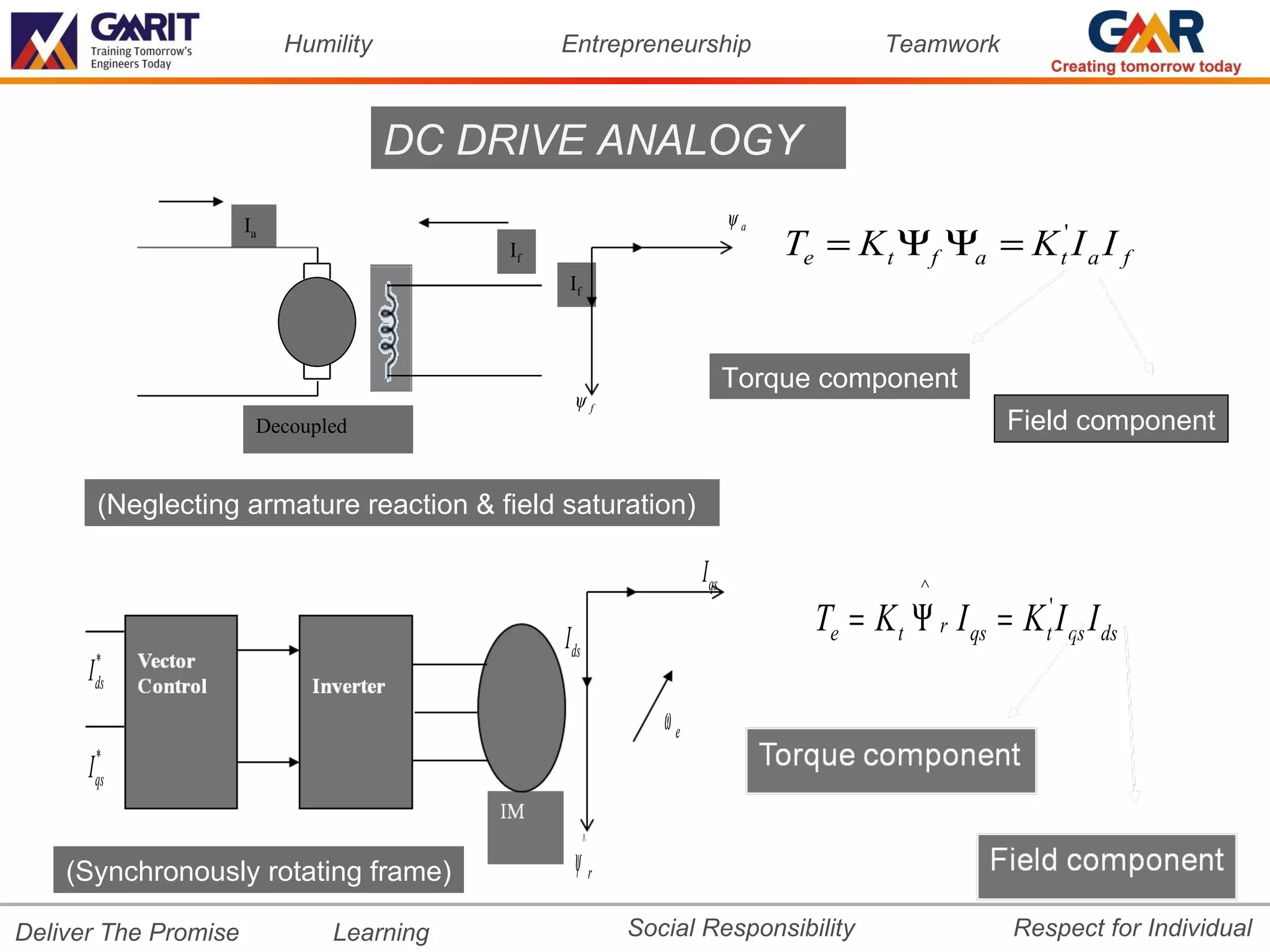
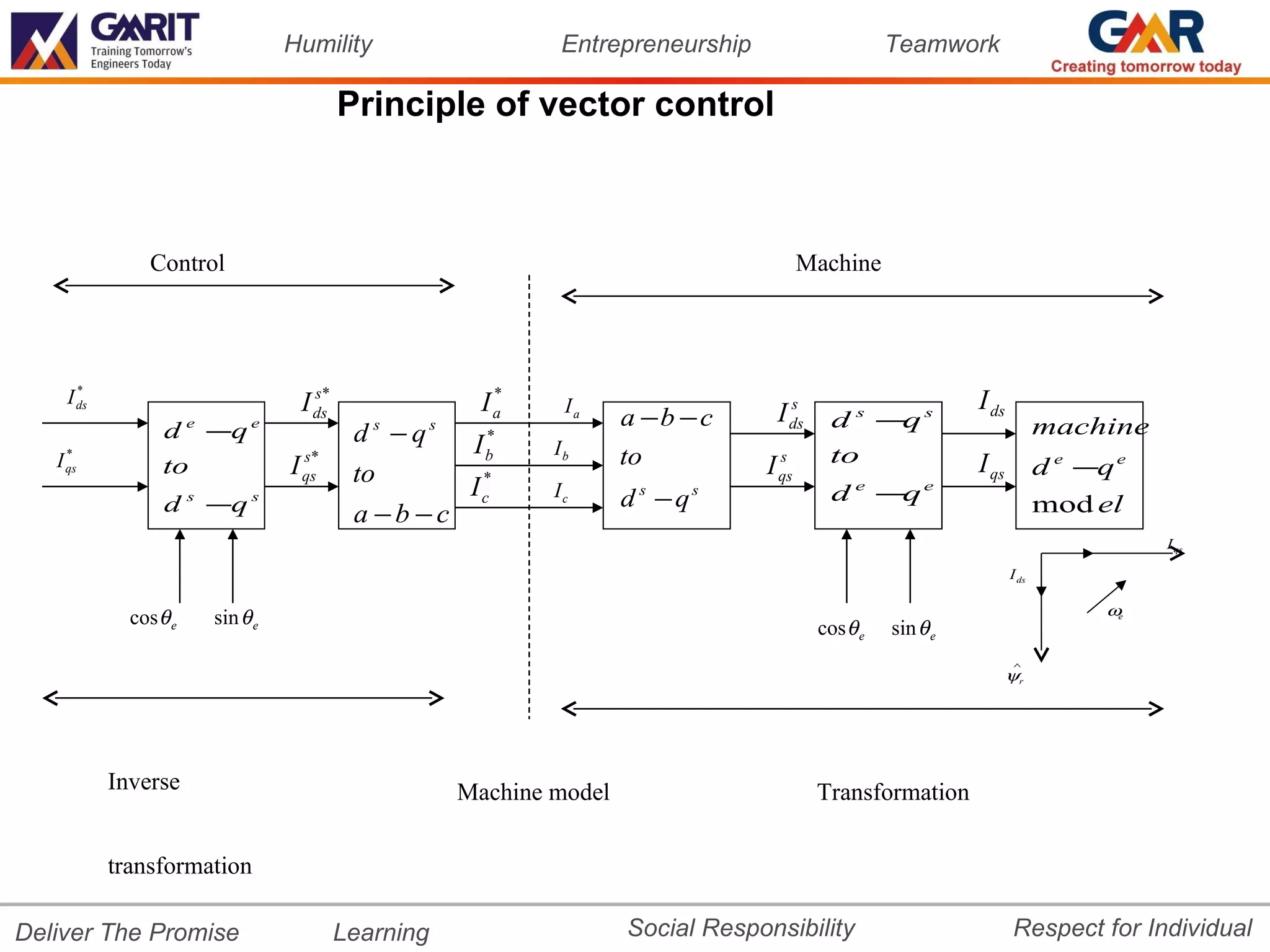
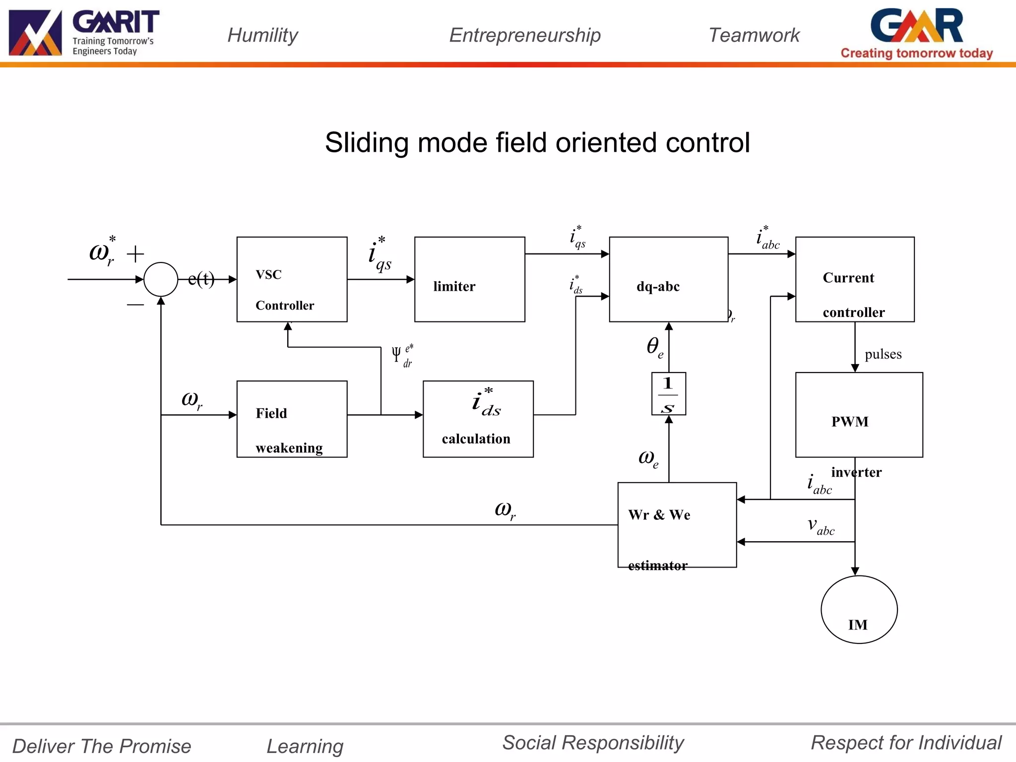
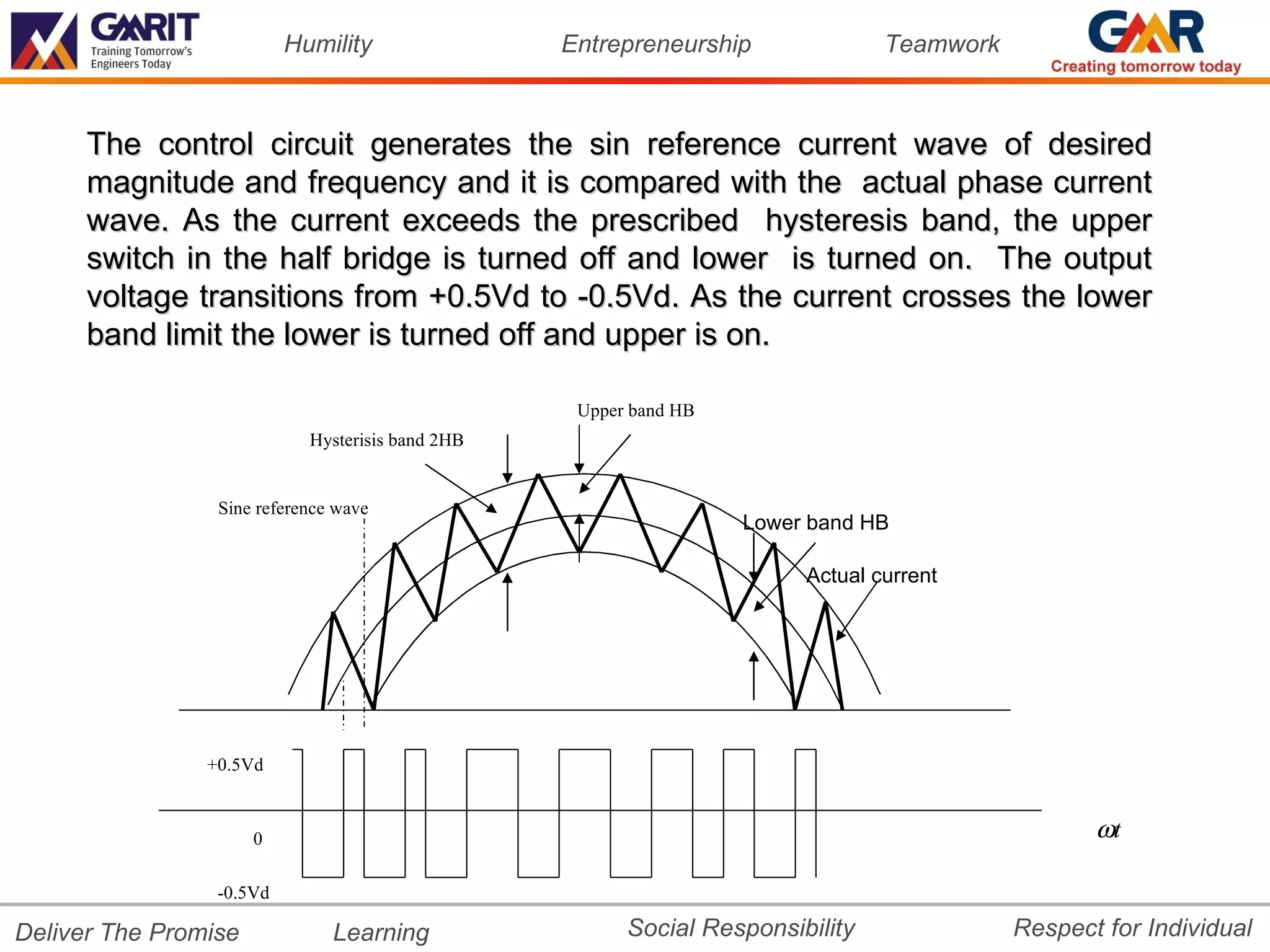
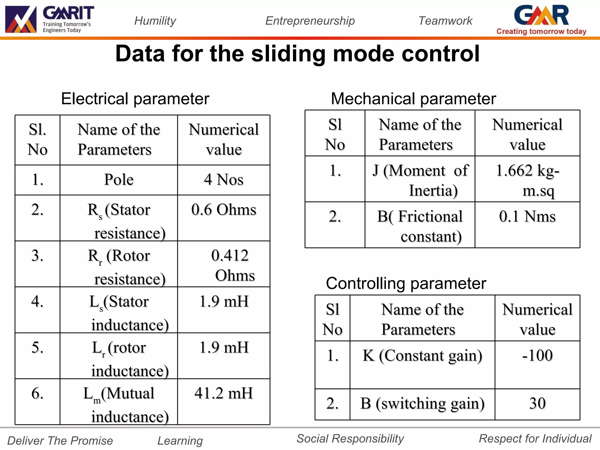
The document presents a sensorless vector control method for 3-phase induction motors using sliding mode field oriented control. It includes rotor speed estimation from stator voltage and current measurements, which is then used as feedback in field oriented control without shaft sensors. The paper proposes a new sensorless vector control approach combining speed estimation to overcome the need for speed sensors, with a variable structure control law using an integral sliding surface to compensate for uncertainties in the system.