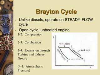
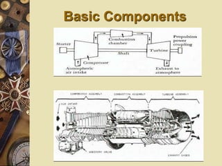
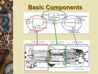
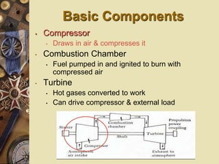
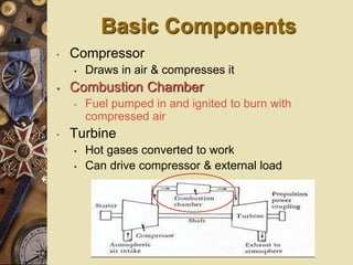
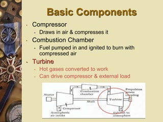
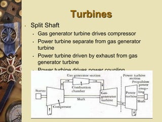
GAS TURBINE ENGINE
Gas Turbine Engine
and Construction
Introduction
• Comprehend the thermodynamic
processes occurring in a gas turbine
• Comprehend the basic components of
gas turbine engines and their basic
operation
• Comprehend the support systems
associated with gas turbine engines
Brayton Cycle
• Unlike diesels, operate on STEADY-FLOW
cycle
• Open cycle, unheated engine
1-2: Compression
2-3: Combustion
3-4: Expansion through
Turbine and Exhaust
Nozzle
(4-1: Atmospheric
Pressure)
Basic Components
Basic Components
Basic Components
• Compressor
• Draws in air & compresses it
• Combustion Chamber
• Fuel pumped in and ignited to burn with
compressed air
• Turbine
• Hot gases converted to work
• Can drive compressor & external load
Basic Components
• Compressor
• Draws in air & compresses it
• Combustion Chamber
• Fuel pumped in and ignited to burn with
compressed air
• Turbine
• Hot gases converted to work
• Can drive compressor & external load
Basic Components
• Compressor
• Draws in air & compresses it
• Combustion Chamber
• Fuel pumped in and ignited to burn with
compressed air
• Turbine
• Hot gases converted to work
• Can drive compressor & external load
Compressor
• Supplies high pressure air for
combustion process
• Compressor types
• Radial/centrifugal flow compressor
• Axial flow compressor
Compressor
• Radial/centrifugal flow
• Adv: simple design,
good for low
compression ratios
(5:1)
• Disadv: Difficult to
stage, less efficient
• Axial flow
• Good for high
compression ratios
(20:1)
Compressor
• Controlling Load on Compressor
• To ensure maximum efficiency and allow
for flexibility, compressor can be split into
HP & LP sections
• Vane control: inlet vanes/nozzle angles
can be varied to control air flow
• Compressor Stall
• Interruption of air flow due to turbulence
Use of Compressed Air
• Primary Air (30%)
• Passes directly to combustor for
combustion process
• Secondary Air (65%)
• Passes through holes in perforated inner
shell & mixes with combustion gases
• Film Cooling Air (5%)
• Insulates/cools turbine blades
Combustion Chambers
• Where air & fuel are mixed, ignited,
and burned
• Spark plugs used to ignite fuel
• Types
• Can: for small, centrifugal compressors
• Annular: for larger, axial compressors (LM
2500)
• Can-annular: rarely used
Turbines
• Consists of one or more stages
designed to develop rotational energy
• Uses sets of nozzles & blades
• Single shaft
• Power coupling on same shaft as turbine
• Same shaft drives rotor of compressor
and power components
Turbines
• Split Shaft
• Gas generator turbine drives compressor
• Power turbine separate from gas generator
turbine
• Power turbine driven by exhaust from gas
generator turbine
• Power turbine drives power coupling
Gas Turbine Systems
• Air System
• Air intakes are located high up & multiple
filters
• Exhaust discharged out stacks
• Fuel System
• Uses either DFM or JP-5
• Lubrication System
• Supply bearings and gears with oil
Gas Turbine Accessory
Systems
• Starting System
• To get compressor initially rotated, HP air
used (can use electrical also)
• Once at certain RPM, fuel injected and
spark ignited
• Power Transmission System
• Reduction gears used to transfer torque
• With split shaft, turbines can run @
different speeds
GTG vs Steam
• For the same hP,
• Weight reduction of 70%
• Simpler (less maintenance, fewer
components)
• Reduced manning – automated control
• Quicker response time
• Modular replacement
Engine Power Transfer
• Turbojet
• Thrust provided by reaction against expansion
of exhaust gases
• Turbofan
• Thrust provided by reaction against expansion
of large volumes of air
• Marine systems
• Thrust provided by turbine
• SCRAMjet/RAMjet
THANX…
….

Gas turbine engine

  • 1.
  • 2.
  • 3.
    Introduction • Comprehend thethermodynamic processes occurring in a gas turbine • Comprehend the basic components of gas turbine engines and their basic operation • Comprehend the support systems associated with gas turbine engines
  • 4.
    Brayton Cycle • Unlikediesels, operate on STEADY-FLOW cycle • Open cycle, unheated engine 1-2: Compression 2-3: Combustion 3-4: Expansion through Turbine and Exhaust Nozzle (4-1: Atmospheric Pressure)
  • 5.
  • 6.
  • 7.
    Basic Components • Compressor •Draws in air & compresses it • Combustion Chamber • Fuel pumped in and ignited to burn with compressed air • Turbine • Hot gases converted to work • Can drive compressor & external load
  • 8.
    Basic Components • Compressor •Draws in air & compresses it • Combustion Chamber • Fuel pumped in and ignited to burn with compressed air • Turbine • Hot gases converted to work • Can drive compressor & external load
  • 9.
    Basic Components • Compressor •Draws in air & compresses it • Combustion Chamber • Fuel pumped in and ignited to burn with compressed air • Turbine • Hot gases converted to work • Can drive compressor & external load
  • 10.
    Compressor • Supplies highpressure air for combustion process • Compressor types • Radial/centrifugal flow compressor • Axial flow compressor
  • 11.
    Compressor • Radial/centrifugal flow •Adv: simple design, good for low compression ratios (5:1) • Disadv: Difficult to stage, less efficient • Axial flow • Good for high compression ratios (20:1)
  • 12.
    Compressor • Controlling Loadon Compressor • To ensure maximum efficiency and allow for flexibility, compressor can be split into HP & LP sections • Vane control: inlet vanes/nozzle angles can be varied to control air flow • Compressor Stall • Interruption of air flow due to turbulence
  • 13.
    Use of CompressedAir • Primary Air (30%) • Passes directly to combustor for combustion process • Secondary Air (65%) • Passes through holes in perforated inner shell & mixes with combustion gases • Film Cooling Air (5%) • Insulates/cools turbine blades
  • 14.
    Combustion Chambers • Whereair & fuel are mixed, ignited, and burned • Spark plugs used to ignite fuel • Types • Can: for small, centrifugal compressors • Annular: for larger, axial compressors (LM 2500) • Can-annular: rarely used
  • 15.
    Turbines • Consists ofone or more stages designed to develop rotational energy • Uses sets of nozzles & blades • Single shaft • Power coupling on same shaft as turbine • Same shaft drives rotor of compressor and power components
  • 16.
    Turbines • Split Shaft •Gas generator turbine drives compressor • Power turbine separate from gas generator turbine • Power turbine driven by exhaust from gas generator turbine • Power turbine drives power coupling
  • 17.
    Gas Turbine Systems •Air System • Air intakes are located high up & multiple filters • Exhaust discharged out stacks • Fuel System • Uses either DFM or JP-5 • Lubrication System • Supply bearings and gears with oil
  • 18.
    Gas Turbine Accessory Systems •Starting System • To get compressor initially rotated, HP air used (can use electrical also) • Once at certain RPM, fuel injected and spark ignited • Power Transmission System • Reduction gears used to transfer torque • With split shaft, turbines can run @ different speeds
  • 19.
    GTG vs Steam •For the same hP, • Weight reduction of 70% • Simpler (less maintenance, fewer components) • Reduced manning – automated control • Quicker response time • Modular replacement
  • 20.
    Engine Power Transfer •Turbojet • Thrust provided by reaction against expansion of exhaust gases • Turbofan • Thrust provided by reaction against expansion of large volumes of air • Marine systems • Thrust provided by turbine • SCRAMjet/RAMjet
  • 22.