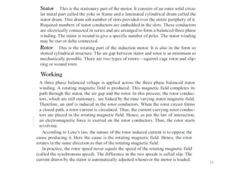
EEE-UNIT 3
1
Machines andDrives
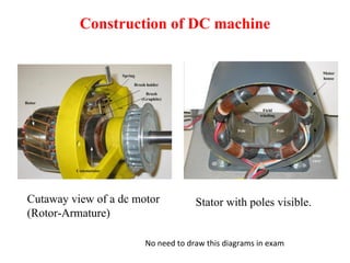
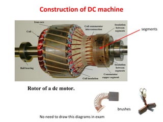
Construction and working principle of DC machines-
Construction and Working principle of a single-phase
Transformer- Construction and working of three phase Inductor
motor, BLDC motor, PMSM, Stepper and Servo motor
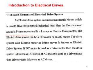
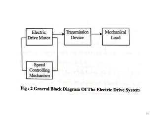
-Introduction to Electrical Drives-Block diagram explanation of
chopper fed DC drives, Selection of drives for real time
applications (cranes/EV/ Pumping applications)
Practice on chopper applications, Demo on DC& AC machines
21EES101T-ELECTRICAL AND
ELECTRONICSENGINEERING
Single Phase Transformer
9
Principleof operation
The transformer works on the principle of electromagnetic induction. In
this case, the conductors are stationary and the magnetic flux is varying
with respect to time. Thus, the induced emf comes under the
classification of statically induced emf.
The transformer is a static piece of apparatus used to transfer electrical
energy
from one circuit to another. The two circuits are magnetically coupled.
One of the circuits is energized by connecting it to a supply at specific
voltage magnitude, frequency and waveform. Then, we have a mutually
induced voltage available across the second circuit at the same
frequency and waveform but with a change in voltage magnitude if
desired. These aspects are indicated in Fig.
10.
10
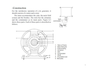
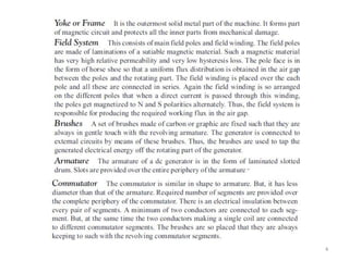
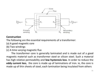
Construction
The following arethe essential requirements of a transformer:
(a) A good magnetic core
(b) Two windings
(c) A time varying magnetic flux
The transformer core is generally laminated and is made out of a good
magnetic material such as transformer steel or silicon steel. Such a material
has high relative permeability and low hysteresis loss. In order to reduce the
eddy current loss, the core is made up of laminations of iron. ie, the core is
made up of thin sheets of steel, each lamination being insulated from others
20
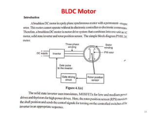
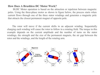
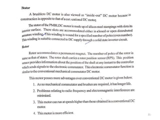
How Does ABrushless DC Motor Work?
BLDC Motor operation is based on the attraction or repulsion between magnetic
poles. Using the three-phase motor as shown in figure below, the process starts when
current flows through one of the three stator windings and generates a magnetic pole
that attracts the closest permanent magnet of opposite pole.
The rotor will move if the current shifts to an adjacent winding. Sequentially
charging each winding will cause the rotor to follow in a rotating field. The torque in this
example depends on the current amplitude and the number of turns on the stator
windings, the strength and the size of the permanent magnets, the air gap between the
rotor and the windings, and the length of the rotating arm.
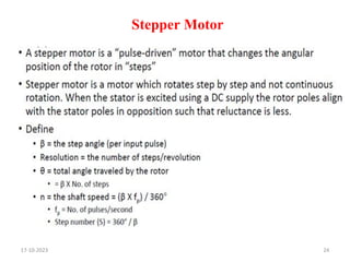
Why Stepper Motor?
•Motor that moves one step at a time
A digital version of an electric motor
Each step is defined by a Step Angle
• Relatively inexpensive
• Ideal for open loop positioning control − Can be implemented
without feedback − Minimizes sensing devices − Just count the
steps
• Torque − Holds its position firmly when not turning − Eliminates
mechanical brakes − Produces better torque than DC motors at
lower speeds
• Positioning applications
25
17-10-2023
26.
Types of SteppingMotors
• Permanent Magnet
− Magnetic rotor
• Variable Reluctance
− Non-magnetic, geared rotor
• Hybrid
− Combines characteristics from PM and VR
− Magnetic, geared rotor
26
17-10-2023
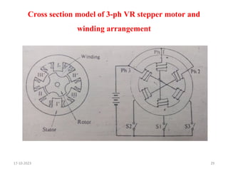
Variable Reluctance StepperMotor
• It consists of a wound stator and a soft iron multi-tooth rotor.
• The stator has a stack of silicon steel laminations on which stator windings
are wound.
• Usually, it is wound for three phases which are distributed between the pole
pairs.
• The rotor carries no windings and is of salient pole type made entirely of
slotted steel laminations.
• The rotor pole’s projected teeth have the same width as that of stator teeth.
• The number of poles on stator differs to that of rotor poles, which provides
the ability to self start and bidirectional rotation of the motor.
17-10-2023 28
29.
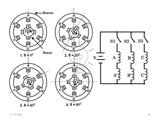
Cross section modelof 3-ph VR stepper motor and
winding arrangement
17-10-2023 29
30.
VR Stepper motorhas following modes of
operation
1. 1 phase ON (or) Full step operation mode
2. 2 phase ON mode
3. Alternate 1 phase ON and 2 phase ON mode (or) Half
step operation mode
4. Micro stepping operation mode
17-10-2023 30
31.
Working of VariableReluctance Stepper Motor
• The stepper motor works on the principle that the rotor aligns in a
particular position with the teeth of the excitation pole in a
magnetic circuit wherein minimum reluctance path exist.
• Whenever power is applied to the motor and by exciting a
particular winding, it produces its magnetic field and develops its
own magnetic poles.
• Due to the residual magnetism in the rotor magnet poles, it will
cause the rotor to move in such a position so as to achieve
minimum reluctance position and hence one set of poles of rotor
aligns with the energized set of poles of the stator.
• At this position, the axis of the stator magnetic field matches with
the axis passing through any two magnetic poles of the rotor.
17-10-2023 31
32.
• When therotor aligns with stator poles, it has enough magnetic force to
hold the shaft from moving to the next position, either in clockwise or
counter clockwise direction.
• The stepper motor works on the principle that the rotor aligns in a
particular position with the teeth of the excitation pole in a magnetic circuit
wherein minimum reluctance path exist.
• Whenever power is applied to the motor and by exciting a particular
winding, it produces its magnetic field and develops its own magnetic
poles.
• Due to the residual magnetism in the rotor magnet poles, it will cause the
rotor to move in such a position so as to achieve minimum reluctance
position and hence one set of poles of rotor aligns with the energized set of
poles of the stator.
• At this position, the axis of the stator magnetic field matches with the axis
passing through any two magnetic poles of the rotor.
• When the rotor aligns with stator poles, it has enough magnetic force to
hold the shaft from moving to the next position, either in clockwise or
counter clockwise direction.
17-10-2023 32
34
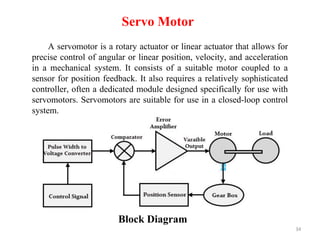
Servo Motor
A servomotoris a rotary actuator or linear actuator that allows for
precise control of angular or linear position, velocity, and acceleration
in a mechanical system. It consists of a suitable motor coupled to a
sensor for position feedback. It also requires a relatively sophisticated
controller, often a dedicated module designed specifically for use with
servomotors. Servomotors are suitable for use in a closed-loop control
system.
Block Diagram
36
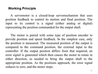
Working Principle
A servomotoris a closed-loop servomechanism that uses
position feedback to control its motion and final position. The
input to its control is a signal (either analog or digital)
representing the position commanded for the output shaft.
The motor is paired with some type of position encoder to
provide position and speed feedback. In the simplest case, only
the position is measured. The measured position of the output is
compared to the command position, the external input to the
controller. If the output position differs from that required, an
error signal is generated which then causes the motor to rotate in
either direction, as needed to bring the output shaft to the
appropriate position. As the positions approach, the error signal
reduces to zero, and the motor stops.
37.
37
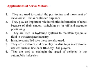
Applications of ServoMotors
1. They are used to control the positioning and movement of
elevators in radio controlled airplanes.
2. They play an important role in robotics information of robot
because of their smooth switching on or off and accurate
positioning.
3. They are used in hydraulic systems to maintain hydraulic
fluid in the aerospace industry.
4. In radio controlled toys these are also used.
5. They are used to extend or replay the disc trays in electronic
devices such as DVDs or Blue-ray Disc players.
6. They are used to maintain the speed of vehicles in the
automobile industries.
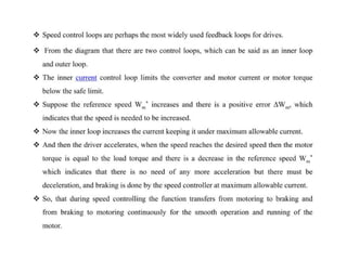
Applications of ElectricDrives
Transportation Systems
Rolling Mills
Paper Mills
Textile Mills
Machine Tools
Fans and Pumps
Robots
Washing Machines etc
45
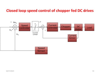
Closed loop speedcontrol of chopper fed DC drives
Δωm
-
+
-
Speed
Controller
Current
Sensor
DC
motor
Load
ωm
+
ωm
*
Chopper
Current
Controller
Speed
Sensor
I*
I
Current
Limiter
10/17/2023 53
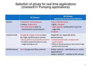
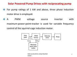
❖ For pumpratings of 1 kW and above, three phase induction
motor drive is employed.
❖ A PWM voltage source inverter with
maximum-power-point-tracker is used for variable frequency
control of the squirrel-cage induction motor.
57
Solar Powered Pump Drives with reciprocating pump
Solar pump drive using induction
motor
58.
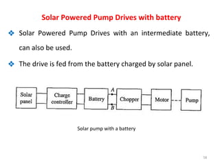
❖ Solar PoweredPump Drives with an intermediate battery,
can also be used.
❖ The drive is fed from the battery charged by solar panel.
58
Solar Powered Pump Drives with battery
Solar pump with a battery
8 Marks Questions
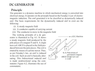
1.Explain the Construction and working principle of DC Generator.
2. Explain the Construction and working principle of DC Motor.
3. Explain the Construction and working principle of single phase transformer.
4. Explain the Construction and working principle of three phase Induction motor.
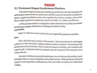
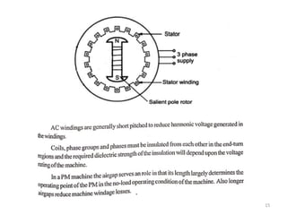
5. Explain the Construction and working principle of PMSM.
6. Explain the Construction and working principle of BLDC motor.
7. Explain the Construction and working principle of any one type of stepper motor. Also
list out applications.
8. With neat block diagram, explain working principle of servo motor. Also list out
applications.
9. With neat block diagram, explain the general layout of electric drives. Also list out the
advantages and application of electric drives.
10. With neat block diagram, explain chopper fed electric drives.
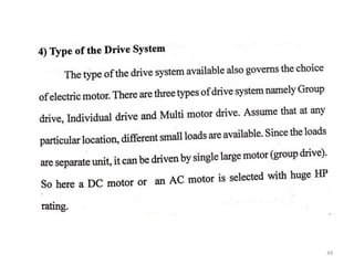
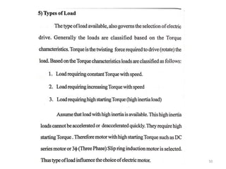
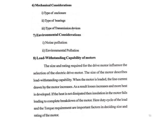
11. List out the factors that should be considered for selecting electric drives.
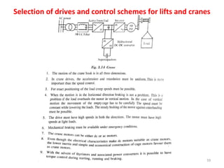
12. List out the factors that should be considered for selecting electric drives for lifts and
cranes.
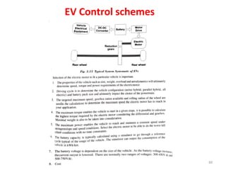
13. List out the factors that should be considered for selecting electric drives for eclectic
vehicles (EV’s) .
14. Explain how electric drives are used for appliance like pumping water.
61