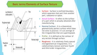
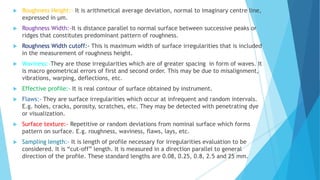
Here is a detailed PPT on the topic related to Basic terms of surface finish, Lay, Reasons for controlling surface roughness, factors affecting surface roughness.
Surface roughness metrology deals with basic terminology of surface,surface roughness indication methods,analysis of surface traces, measurement methods,surface roughness measuring instruments such as Stylus Probe Instrument, Profilometer, Tomlinson Surface Meter ,The Taylor-Hobson Talysurf etc.This is very useful for diploma,degree engineering students of mechanical,production,automobile branch
Please refer this file just as reference material. More concentration should on class room work and text book methodology.
Thermal aspects of Machining, Tool materials, Tool wear Cutting fluids and Machinability.
Experiment No.01
To study the different parts of Lathe machine, milling machine, grinding machine, drilling machine, their functions & types.
Experiment No.02
To Study the Lathe Machine Tools, Accessories, their uses & Limitations while working on lathe machine.
Experiment No.03.
To Study and perform Various Lathe machine operations using lathe machine tools on a given Work piece
Experiment No.04
To Study and perform various milling machine operations using different milling machine tools on a given Work piece
Experiment No.05
To Study and perform drilling/tapping/reaming machine operations using different drilling machine tools on a given Work piece.
Experiment No.06
To study and perform grinding machine operations using different grinding machine tools on a given Work piece.
Experiment No.07
To Study and perform shaper/planner machine operations on a given Work piece.
Experiment No.08
To study the different parts of CNC machining centre, CNC turning centre, their functions & types.
Experiment No.09
To Study and perform various machining operations of CNC machines on a given Work piece.
Experiment No.10
To Study an overview of CNC programming, CNC tools, work holding devices of CNC machines and control panel of CNC machines.
CHEMICAL MACHINING - NON TRADITIONAL MACHININGSajal Tiwari
The chemical machining processes include those wherein material removal is accomplished by a chemical reaction, sometimes assisted by electrical or thermal energy applications. This group includes chemical milling, photochemical machining, and thermo-chemical machining.
education is a key for everything so the objective of this slide is to share knowledge to the glob in my area of specialization.
This lecture note is basically designed for mechanical Engineering Manufacturing stream students and Instructors.
Cutting power & Energy Consideration in metal cuttingDushyant Kalchuri
Cutting power is an important parameter, especially in the case of rough operations, as it makes it possible to:
select and invest in a machine with a power output suited to the operation being carried out
obtain the cutting conditions that allow the machine's power to be used in the most effective way possible, so as to ensure optimal material removal rate while taking into account the capacity of the tool being used.
Concepts of Surface Metro logy, Introduction to Surface Texture, Terminology of Surface Texture, Analysis of Surface Traces, Peak to valley height of roughness ,The average roughness,Form factor & Bearing curve, Specification of Surface Texture Characteristics
Surface roughness metrology refers to the measurement and quantification of the minute variations, irregularities, and finer details present on the surface of an object. Surface roughness is a crucial aspect in various industries, such as manufacturing, engineering, and quality control, as it significantly affects the functionality, performance, and appearance of products.
Surface roughness metrology involves the use of specialized tools and techniques to measure and characterize the topography of a surface. Some common methods and instruments used for surface roughness measurement include:
Contact Profilometers: These instruments use a physical stylus or probe that moves along the surface to measure its profile. The stylus records the vertical deviations in the surface, which are used to calculate roughness parameters like Ra (average roughness), Rz (average maximum peak to valley height), Rq (root mean square roughness), etc.
Non-Contact Profilometers: Optical and laser-based systems, such as confocal microscopy, interferometry, and focus variation, measure surface roughness without physically touching the surface. These methods use light, lasers, or other non-contact mechanisms to capture surface details.
Atomic Force Microscopy (AFM): AFM uses a tiny cantilever with a sharp tip to scan the surface at a nanoscale level, producing a 3D profile of the surface. It's highly accurate for measuring extremely small surface features and roughness.
White Light Interferometry: This method uses white light to measure the surface height variations by analyzing interference patterns produced by the reflected light.
Surface roughness measurements are typically expressed using various parameters, including:
Ra (Average Roughness): Arithmetic mean deviation of the roughness profile from the mean line.
Rz (Maximum Height of the Profile): The distance between the highest peak and the lowest valley within a sampling length.
Rq (Root Mean Square Roughness): The root mean square of the roughness profile deviations.
Understanding and quantifying surface roughness is crucial for several reasons:
Quality Control: Ensures that manufactured parts meet specified surface quality standards.
Functionality: Impacts how well parts interact, move, seal, or perform their intended functions.
Performance: Affects friction, wear, and corrosion resistance of components.
Appearance: Influences the visual and tactile perception of a product.
Accurate surface roughness metrology allows manufacturers to control and optimize their processes, resulting in better product performance, durability, and appearance.
Experimental Investigation of Effect of Tool Length on Surface Roughness duri...IOSR Journals
: In the turning operation, vibration is a frequent problem, which affects the result of the machining
and in particular the surface finish. Tool life is also influenced by vibrations. Severe acoustic noise in the
working environment frequently results as a dynamic motion between the cutting tool and the work piece. In all
cutting operations like turning, boring and milling vibrations are induced due to deformation of the work piece.
In the turning process, the importance of machining parameter choice is increased, as it controls the surface
quality required. Tool overhang is a cutting tool parameter that has not been investigated in as much detail as
some of the better known ones. It is appropriate to keep the tool overhang as short as possible; however, a
longer tool overhang may be required depending on the geometry of the work piece and when using the holeturning
process in particular. In this study, we investigate the effects of changes in the tool overhang in the
external turning process on both the surface quality of the work piece and tool wear. For this purpose, we used
work pieces of AISI 1050 material with diameters of 20, 30, and 40 mm; and the surface roughness of the work
piece were determined through experiments using constant cutting speed and feed rates with different depth of
cuts (DOCs) and tool overhangs. We observed that the effect of the DOC on the surface roughness is negligible,
but tool overhang is more important. The deflection of the cutting tool increases with tool overhang. Two
different analytical methods were compared to determine the dependence of tool deflection on the tool
overhang. Also, the real tool deflection values were determined using a comparator. We observed that the tool
deflection values were quite compatible with the tool deflection results obtained using the second analytical
method.
DETERMINING THE INFLUENCE OF CUTTING FLUID ON SURFACE ROUGHNESS DURING MACHIN...Journal For Research
Evaluation of the performance of cutting fluid in machining different work materials in order to improve the efficiency of any machining process. The efficiency can be evaluated based on certain process parameters such as flank wear, surface roughness on the work piece, cutting force developed, temperature developed at the tool-chip interface, etc. The main aim of the project is to determine the influence of cutting fluids in metal working. Servo 68 is mainly used for investigation based on surface roughness during milling of EN24 and EN8 steel with carbide tool. Three square pieces of EN 24 material and three round pieces of EN8 material are taken for machining. Different cutting parameters are considered for feed rate, speed and depth of cut. the six pieces are machined with different parameters and surface roughness values are investigated experimentally.
Mass media finishing techniques improve part performance and service life, and these processes can be tailored or modified to amplify this effect. Although the ability of these processes to drive down deburring and surface finishing costs when compared to manual procedures is well known and documented, their ability to dramatically effect part performance and service life are not. This facet of edge and surface finishing deserves closer scrutiny and this is also true of larger and more complex parts – only more so
Automobile Management System Project Report.pdfKamal Acharya
The proposed project is developed to manage the automobile in the automobile dealer company. The main module in this project is login, automobile management, customer management, sales, complaints and reports. The first module is the login. The automobile showroom owner should login to the project for usage. The username and password are verified and if it is correct, next form opens. If the username and password are not correct, it shows the error message.
When a customer search for a automobile, if the automobile is available, they will be taken to a page that shows the details of the automobile including automobile name, automobile ID, quantity, price etc. “Automobile Management System” is useful for maintaining automobiles, customers effectively and hence helps for establishing good relation between customer and automobile organization. It contains various customized modules for effectively maintaining automobiles and stock information accurately and safely.
When the automobile is sold to the customer, stock will be reduced automatically. When a new purchase is made, stock will be increased automatically. While selecting automobiles for sale, the proposed software will automatically check for total number of available stock of that particular item, if the total stock of that particular item is less than 5, software will notify the user to purchase the particular item.
Also when the user tries to sale items which are not in stock, the system will prompt the user that the stock is not enough. Customers of this system can search for a automobile; can purchase a automobile easily by selecting fast. On the other hand the stock of automobiles can be maintained perfectly by the automobile shop manager overcoming the drawbacks of existing system.
Vaccine management system project report documentation..pdfKamal Acharya
The Division of Vaccine and Immunization is facing increasing difficulty monitoring vaccines and other commodities distribution once they have been distributed from the national stores. With the introduction of new vaccines, more challenges have been anticipated with this additions posing serious threat to the already over strained vaccine supply chain system in Kenya.
COLLEGE BUS MANAGEMENT SYSTEM PROJECT REPORT.pdfKamal Acharya
The College Bus Management system is completely developed by Visual Basic .NET Version. The application is connect with most secured database language MS SQL Server. The application is develop by using best combination of front-end and back-end languages. The application is totally design like flat user interface. This flat user interface is more attractive user interface in 2017. The application is gives more important to the system functionality. The application is to manage the student’s details, driver’s details, bus details, bus route details, bus fees details and more. The application has only one unit for admin. The admin can manage the entire application. The admin can login into the application by using username and password of the admin. The application is develop for big and small colleges. It is more user friendly for non-computer person. Even they can easily learn how to manage the application within hours. The application is more secure by the admin. The system will give an effective output for the VB.Net and SQL Server given as input to the system. The compiled java program given as input to the system, after scanning the program will generate different reports. The application generates the report for users. The admin can view and download the report of the data. The application deliver the excel format reports. Because, excel formatted reports is very easy to understand the income and expense of the college bus. This application is mainly develop for windows operating system users. In 2017, 73% of people enterprises are using windows operating system. So the application will easily install for all the windows operating system users. The application-developed size is very low. The application consumes very low space in disk. Therefore, the user can allocate very minimum local disk space for this application.
Democratizing Fuzzing at Scale by Abhishek Aryaabh.arya
Presented at NUS: Fuzzing and Software Security Summer School 2024
This keynote talks about the democratization of fuzzing at scale, highlighting the collaboration between open source communities, academia, and industry to advance the field of fuzzing. It delves into the history of fuzzing, the development of scalable fuzzing platforms, and the empowerment of community-driven research. The talk will further discuss recent advancements leveraging AI/ML and offer insights into the future evolution of the fuzzing landscape.
Final project report on grocery store management system..pdfKamal Acharya
In today’s fast-changing business environment, it’s extremely important to be able to respond to client needs in the most effective and timely manner. If your customers wish to see your business online and have instant access to your products or services.
Online Grocery Store is an e-commerce website, which retails various grocery products. This project allows viewing various products available enables registered users to purchase desired products instantly using Paytm, UPI payment processor (Instant Pay) and also can place order by using Cash on Delivery (Pay Later) option. This project provides an easy access to Administrators and Managers to view orders placed using Pay Later and Instant Pay options.
In order to develop an e-commerce website, a number of Technologies must be studied and understood. These include multi-tiered architecture, server and client-side scripting techniques, implementation technologies, programming language (such as PHP, HTML, CSS, JavaScript) and MySQL relational databases. This is a project with the objective to develop a basic website where a consumer is provided with a shopping cart website and also to know about the technologies used to develop such a website.
This document will discuss each of the underlying technologies to create and implement an e- commerce website.
Welcome to WIPAC Monthly the magazine brought to you by the LinkedIn Group Water Industry Process Automation & Control.
In this month's edition, along with this month's industry news to celebrate the 13 years since the group was created we have articles including
A case study of the used of Advanced Process Control at the Wastewater Treatment works at Lleida in Spain
A look back on an article on smart wastewater networks in order to see how the industry has measured up in the interim around the adoption of Digital Transformation in the Water Industry.
About
Indigenized remote control interface card suitable for MAFI system CCR equipment. Compatible for IDM8000 CCR. Backplane mounted serial and TCP/Ethernet communication module for CCR remote access. IDM 8000 CCR remote control on serial and TCP protocol.
• Remote control: Parallel or serial interface.
• Compatible with MAFI CCR system.
• Compatible with IDM8000 CCR.
• Compatible with Backplane mount serial communication.
• Compatible with commercial and Defence aviation CCR system.
• Remote control system for accessing CCR and allied system over serial or TCP.
• Indigenized local Support/presence in India.
• Easy in configuration using DIP switches.
Technical Specifications
Indigenized remote control interface card suitable for MAFI system CCR equipment. Compatible for IDM8000 CCR. Backplane mounted serial and TCP/Ethernet communication module for CCR remote access. IDM 8000 CCR remote control on serial and TCP protocol.
Key Features
Indigenized remote control interface card suitable for MAFI system CCR equipment. Compatible for IDM8000 CCR. Backplane mounted serial and TCP/Ethernet communication module for CCR remote access. IDM 8000 CCR remote control on serial and TCP protocol.
• Remote control: Parallel or serial interface
• Compatible with MAFI CCR system
• Copatiable with IDM8000 CCR
• Compatible with Backplane mount serial communication.
• Compatible with commercial and Defence aviation CCR system.
• Remote control system for accessing CCR and allied system over serial or TCP.
• Indigenized local Support/presence in India.
Application
• Remote control: Parallel or serial interface.
• Compatible with MAFI CCR system.
• Compatible with IDM8000 CCR.
• Compatible with Backplane mount serial communication.
• Compatible with commercial and Defence aviation CCR system.
• Remote control system for accessing CCR and allied system over serial or TCP.
• Indigenized local Support/presence in India.
• Easy in configuration using DIP switches.
Quality defects in TMT Bars, Possible causes and Potential Solutions.PrashantGoswami42
Maintaining high-quality standards in the production of TMT bars is crucial for ensuring structural integrity in construction. Addressing common defects through careful monitoring, standardized processes, and advanced technology can significantly improve the quality of TMT bars. Continuous training and adherence to quality control measures will also play a pivotal role in minimizing these defects.
Hybrid optimization of pumped hydro system and solar- Engr. Abdul-Azeez.pdffxintegritypublishin
Advancements in technology unveil a myriad of electrical and electronic breakthroughs geared towards efficiently harnessing limited resources to meet human energy demands. The optimization of hybrid solar PV panels and pumped hydro energy supply systems plays a pivotal role in utilizing natural resources effectively. This initiative not only benefits humanity but also fosters environmental sustainability. The study investigated the design optimization of these hybrid systems, focusing on understanding solar radiation patterns, identifying geographical influences on solar radiation, formulating a mathematical model for system optimization, and determining the optimal configuration of PV panels and pumped hydro storage. Through a comparative analysis approach and eight weeks of data collection, the study addressed key research questions related to solar radiation patterns and optimal system design. The findings highlighted regions with heightened solar radiation levels, showcasing substantial potential for power generation and emphasizing the system's efficiency. Optimizing system design significantly boosted power generation, promoted renewable energy utilization, and enhanced energy storage capacity. The study underscored the benefits of optimizing hybrid solar PV panels and pumped hydro energy supply systems for sustainable energy usage. Optimizing the design of solar PV panels and pumped hydro energy supply systems as examined across diverse climatic conditions in a developing country, not only enhances power generation but also improves the integration of renewable energy sources and boosts energy storage capacities, particularly beneficial for less economically prosperous regions. Additionally, the study provides valuable insights for advancing energy research in economically viable areas. Recommendations included conducting site-specific assessments, utilizing advanced modeling tools, implementing regular maintenance protocols, and enhancing communication among system components.
TECHNICAL TRAINING MANUAL GENERAL FAMILIARIZATION COURSEDuvanRamosGarzon1
AIRCRAFT GENERAL
The Single Aisle is the most advanced family aircraft in service today, with fly-by-wire flight controls.
The A318, A319, A320 and A321 are twin-engine subsonic medium range aircraft.
The family offers a choice of engines
TECHNICAL TRAINING MANUAL GENERAL FAMILIARIZATION COURSE
Surface finish Metrology
1. Made by:-
Udit J. Modi
B.Tech, Mechanical Engineering, Nirma University
Basic terms of surface finish, Lay, Reasons for
controlling surface roughness, factors
affecting surface roughness
Topic
2. Basic terms/Elements of Surface Texture
Surface:- Surface is confined boundary
which separates that part from another
part, substance or space.
Actual Surface:- It refers to the surface
of a part which is actually obtained after
manufacturing.
Nominal Surface:- It is a theoretical,
geometrically perfect surface which does
not exist in practice. It is an average of
the irregularities that are superimposed.
Profile:- It is defined as the contour of
any section through surface.
Roughness:- It is relatively finely spaced
microgeometrical irregularities. It is
called primary texture and have fourth
and third order irregularities.
3. Roughness Height:- It is arithmetical average deviation, normal to imaginary centre line,
expressed in μm.
Roughness Width:-It is distance parallel to normal surface between successive peaks or
ridges that constitutes predominant pattern of roughness.
Roughness Width cutoff:- This is maximum width of surface irregularities that is included
in the measurement of roughness height.
Waviness:-They are those irregularities which are of greater spacing in form of waves. It
is macro geometrical errors of first and second order. This may be due to misalignment,
vibrations, warping, deflections, etc.
Effective profile:- It is real contour of surface obtained by instrument.
Flaws:- They are surface irregularities which occur at infrequent and random intervals.
E.g. holes, cracks, porosity, scratches, etc. They may be detected with penetrating dye
or visualization.
Surface texture:- Repetitive or random deviations from nominal surface which forms
pattern on surface. E.g. roughness, waviness, flaws, lays, etc.
Sampling length:- It is length of profile necessary for irregularities evaluation to be
considered. It is “cut-off” length. It is measured in a direction parallel to general
direction of the profile. These standard lengths are 0.08, 0.25, 0.8, 2.5 and 25 mm.
4. LAY
The Lay is the direction of
the predominant surface
pattern produced by tool
marks or scratches.
It is usually determined by
the production method
used to process the surface.
It should be noted that
surface roughness is
measured at 90˚ to the
direction of lay.
LAY AND ITS TYPES
5. Symbols
||
• parallel = Lay parallel to boundary line of the nominal surface.
• It is lay parallel to the line representing surface to which symbol is applied.
Example
• E.g. parallel shaping , end view of turning and O.D. grinding
• Perpendicular = Lay perpendicular to the boundary line of nominal surface.
• It is lay perpendicular to the line representing surface to which symbol is
applied.
Example
• E.g. end view of shaping , longitudinal view of turning and O.D. grinding
6. X
• Angular = Lay is angular in both directions to the line
representing the surface to which symbol is applied
Example
• e.g. Traversed end mill, side wheel grinding
M
• Lay is Multidirectional (can be any directions
possible)
Example
• e.g. lapping, Honing, Super-finishing
7. C
• Circular = Lay is approximately circular relative to the
centre of the surface to which the symbol is applied.
Example
• e.g. Facing operation in a lathe machine
R
• Radial = Lay is approximately radial relative to the
centre of the surface to which the symbol is applied.
Example
• e.g. Surface ground on a turntable, fly cut and indexed
on end mill
P
• This Lay indicates that lay is non-directional,
particulate and protuberant.
Example
• e.g. Reaming, Finishing processes, Rubbing
8. Reasons for controlling Surface Texture
The main reasons to control surface texture are:
1) To reduce initial wear of parts increasing efficient & consistent performance and
reasonable life.
2) To improve the service life of the components increasing Durability and
Reliability with integrating ,developing and improving Quality Control.
3) To have a close dimensional tolerance on the parts due to which the job is not
allowed to go away from accuracy and perfectness without causing any
functional trouble, when assembled with its mating part and put it into actual
service.
4) To reduce frictional wear and tear on the assembly parts.
5) To have aesthetic look and attractiveness or for better appearance.
6) To reduce corrosion on the surface by minimising depth of fined spaced micro-
geometrical irregularities.
7) If the surface is not smooth enough, a turning shaft may act or brhave like a
reamer and the piston rod like a broach. The moving parts can heat up, bind and
freeze.
8) To improve the fatigue resistance as when the surface roughness increases, the
crack may propagate resulting in fatigue failure.
9. Examples
Different requirements may demand different surface texture.
Excessive surface roughness on shafts and bearings say in an electrical
household appliances require more power. So, here smooth surface finish is
needed.
Brake Drums and Clutch plates etc. work best with some allowable degree of
surface roughness.
Examples
Surface finish on shaft
10. Heat Exchanger tubes transfer heat better when their surfaces are slightly
rough rather than highly finished.
For components which are subjected to load reversals, sharp irregularities act
as stress raisers constituting the greatest potential source of fatigue cracks,
therefore, the surface of the parts which are subjected to high stresses and
load reversals are finished highly smooth.
11. Factors affecting Surface Roughness
Plenty of factors plays an important role in determining Surface Roughness:-
(1)Vibrations:
Wear on the component, loose mounting, misalignment ,etc. are causes of vibration which will
be further vibrate the work-piece or cutting tool. That is why Oscillations or Vibrations affect
the surface texture.
(2)Cutting Speed Condition:
It is found that an increase of cutting speed generally improves surface quality.
(3)Material of work-piece:
Higher work material hardness results in better surface finish. To predict actual surface
roughness, first compute ideal surface roughness and then multiply with ratio from the graph.
12. (4) Depth of cut:
Increasing the depth of cut increases the cutting resistance and the amplitude of
vibrations. As a result, cutting temperature also rises. Therefore, it is expected that
surface quality will deteriorate.
(5) Type of Machining:
Irregularities will still be present after doing turning, grinding, lapping, boring, shaping,
drilling, etc. to finish the surface.
Lapping and Honing produce a texture irregular and multidirectional
Grinding, most used as finishing process, may give texture irregular and unidirectional.
Turning, facing, boring, shaping, etc. tend to give spaced and unidirectional.
13. (6)Engagement of the cutting tool:
This factor acts in the same way as the depth of cut.
(7)Type, form, material and sharpness of cutting tool:
The irregularities of the cutting edge due to wear and material of tool are reproduced on the
machined surface.
Apart from that, as tool wear increases, other dynamic phenomena such as excessive
vibrations will occur, thus further deteriorating surface quality.
Increasing the tool rake angle improves surface finish.
(8)Feed Condition:
Experiments show that as feed rate increases surface roughness also increases due to the
increase in cutting force.
14. (9) Type of Coolant used:
Cutting fluids affect the surface finish by changing cutting temperature.
It absorbs the heat that is generated during cutting by cooling mainly the
tool point and the work surface. In addition to this, the cutting fluid is
able to reduce the friction between the rake face and the chip as well as
between the flank and the machined surface.
Lastly, the washing action of the cutting fluid is considerable, as it
consists in removing chip fragments and wear particles. Therefore, the
quality of a surface machined with the presence of cutting fluid is
expected to be better than that obtained from dry cutting.
(10) Rigidity of the system consisting of machine tool, fixture of cutting
tool and work:
The improper mounting of the above mentioned may create additional
force or gives rise to vibrations or oscillations to worsen the surface
finish.
15. Contact pressure of bodies 1μm roughness and 5 μm roughness from ANSYS 13.0 is shown below:-
It is clear that maximum contact pressure of 1 μm roughness is 0.899980 MPa while that of 5 μm
roughness is 0.90086 MPa.The contact is having 0.9001 MPa contact pressure which is higher than
maximum contact pressureo1 1 μm roughness contact. So, With increase in surface roughness,
contact pressure increases along with rise in thermal & electrical resistance.
Experimental data shows graph of heat transfer
co-efficient V/S surface roughness
16. International Journal for Research in Applied Science & Engineering Technology
(IJRASET)
N. Dhar, M. Kamruzzaman(2006),Cutting temperature, toolwear, surface roughness
and dimensional deviation in AISI4037 steel
Dimension, Tolerances and Related Attributes of Surfaces and Effect of
Manufacturing Processes
Textbook of Metrology By M. Mahajan
Mitutoyo America Corporation (www.mitutoyo.com)
Whitehouse, David (2012). Surfaces and their Measurement. Boston: Butterworth-
Heinemann
J. a. J.B.P. Wiliamson, “contact of nominally flat Surfaces”, in Proceeding of Royal
Society, London, 1966.
REFERENCES