Download as PDF, PPTX
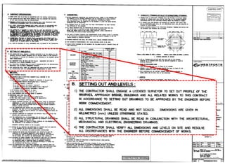
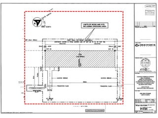
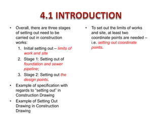
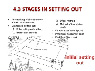


There are three main stages of setting out that must be carried out for construction projects: 1. Initial setting out of the site limits and boundaries 2. Setting out the foundations and major site elements in the first stage 3. Setting out precise design points and dimensions in the second stage Horizontal and vertical control points must be established to accurately position all design aspects according to the drawings and specifications. Proper planning and protection of control points is important to ensure correct construction.


