Downloaded 215 times
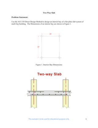
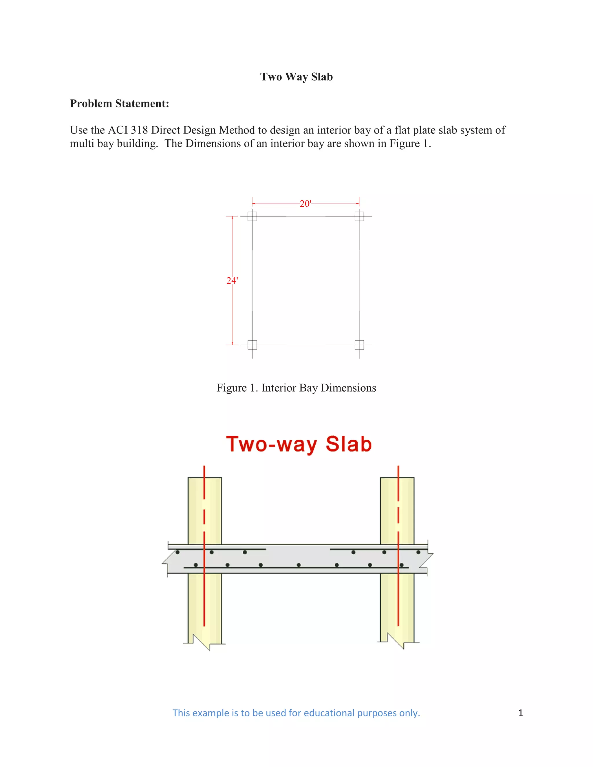

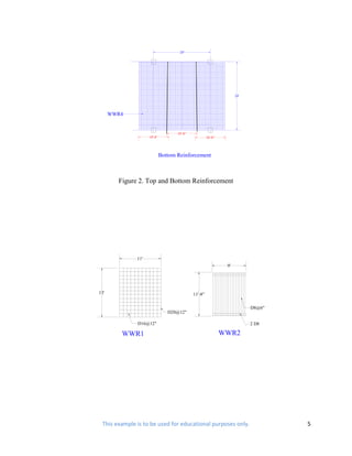
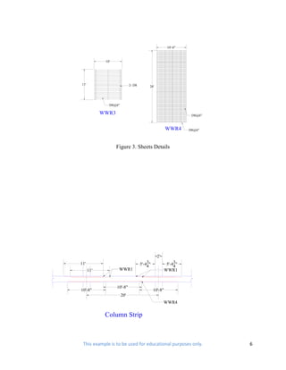
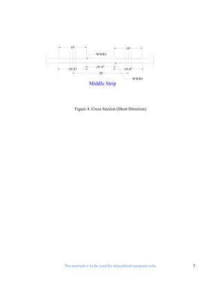
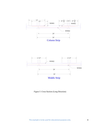

This document summarizes the design of the reinforcement for an interior bay of a two-way flat plate concrete slab system. The slab was designed using the ACI 318 Direct Design Method. Reinforcement details and quantities are provided for welded wire reinforcement in both short and long slab directions. The steel weight per square foot using welded wire reinforcement is 1.93 lbs, compared to 2.51 lbs using grade 60 rebar, representing a 23% savings in steel weight.


