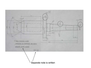
- An engineering component's surface may require additional machining beyond casting, forging, or other initial processes to meet functional requirements. Not all surfaces need the same level of finishing.
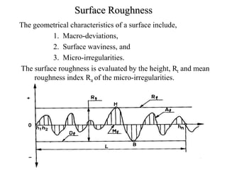
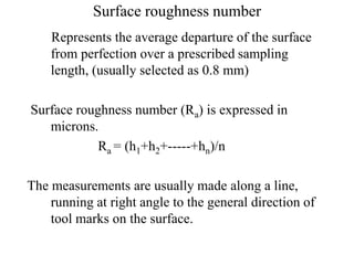
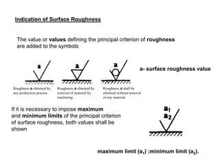
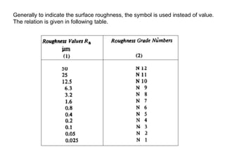
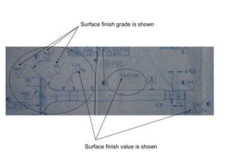
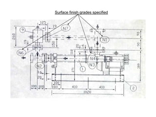
- Surface roughness is evaluated by the height and mean roughness index of micro-irregularities on the surface. It is measured along a line perpendicular to tool marks and expressed as an average roughness number Ra in microns.
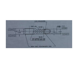
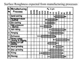
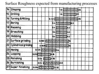
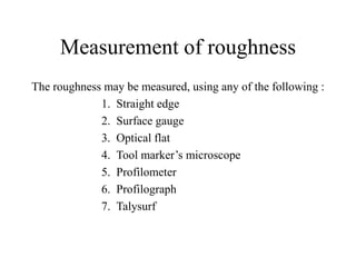
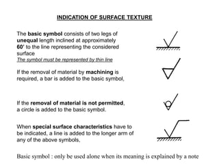
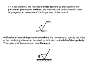
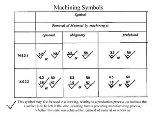
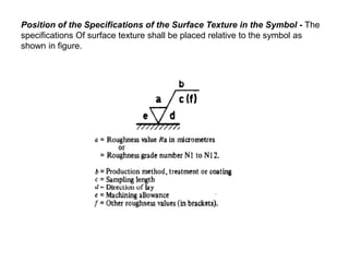
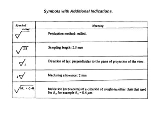
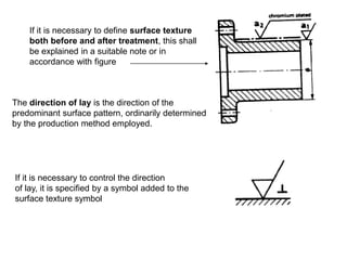
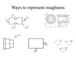
- Different manufacturing processes produce characteristic levels of surface roughness that can be specified on drawings using standard symbols and notes to indicate roughness requirements.