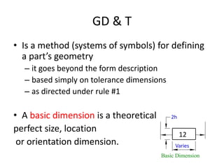
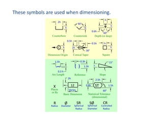
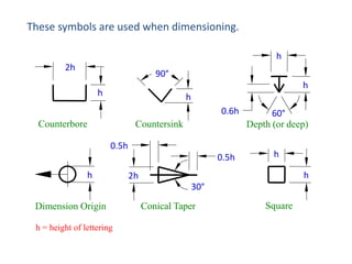
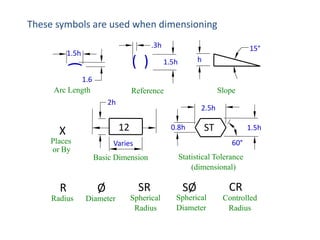
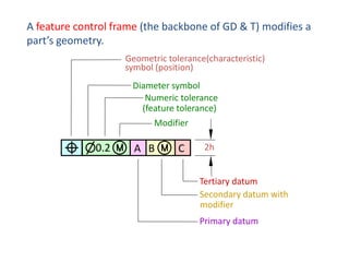
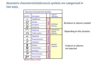
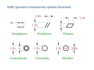
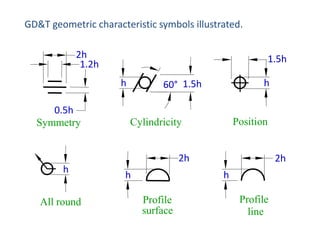
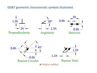
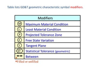
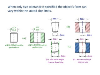
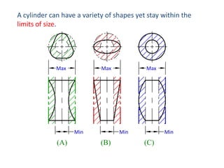
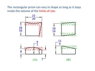
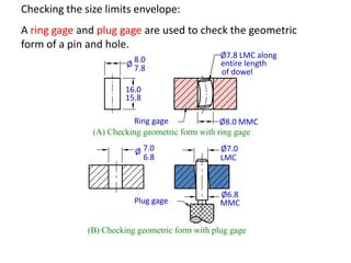
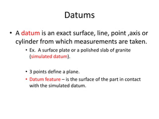
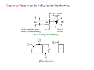
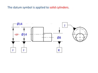
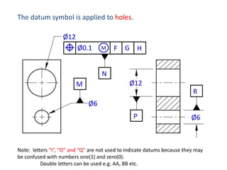
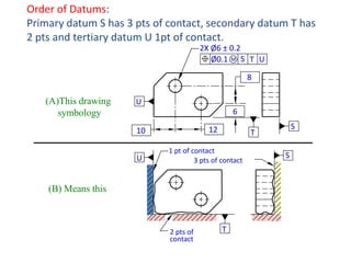
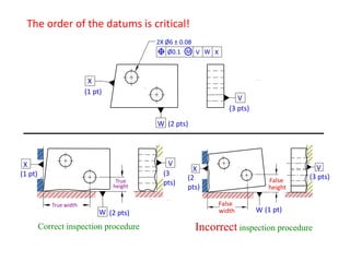
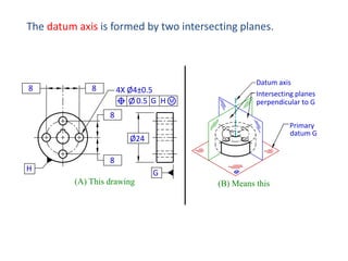
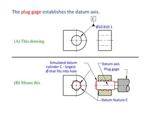
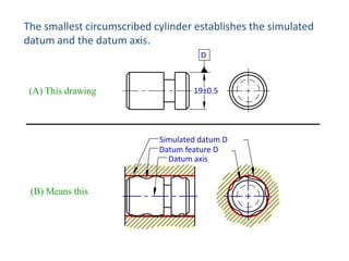
This document provides information about geometric dimensioning and tolerancing (GD&T). It defines GD&T as a method for defining the geometry of a part beyond simple tolerance dimensions. Feature control frames modify a part's geometry and include the geometric tolerance symbol, datum, and modifiers. Geometric characteristic symbols indicate the type of tolerance such as flatness, circularity, or perpendicularity. Datums establish the reference frame for measurements and include primary, secondary, and tertiary datums indicated on drawings.
GD&T is an international way of describing a part accurately. It is used widely in all manufacturing sectors for part dimensioning. This ppt contains basic overview of GD&T. The detailed version will be uploaded soon.
GD&T is a means of dimensioning & tolerancing a drawing which considers the function of the part and how this part functions with related parts.
GD&T has increased in practice in last 15 years because of ISO 9000.
ISO 9000 requires not only that something be required, but how it is to be controlled. For example, how round does a round feature have to be?
GD&T is a system that uses standard symbols to indicate tolerances that are based on the feature’s geometry.
Sometimes called feature based dimensioning & tolerancing or true position dimensioning & tolerancing
GD&T practices are specified in ANSI Y14.5M-1994.
A basic 2 day training on understanding of GDnT,Geometrical Dimensioning & Tolerancing to Technical & Egineering Group as a common language in understanding Drawings.
Trainer & Speaker
Timothy Wooi,
20C,Taman Bahagia,06000,Jitra, Kedah. Malaysia
email: timothywooi2@gmail.com
GD&T for Omega Fabrication, Melaka.4-5th March 2017Timothy Wooi
GD&T Course Objective
Provide Participants with Fundamental concepts of GD&T to express, understand and interpret drawing requirements using GD&T to ASME Y14.5 Standards.
To allow Participants to master techniques of GD&T in the ASME standard to;
integrate smoothly into engineering design applications and modern inspection systems at work.
GD&T stands for Geometric Dimensioning and Tolerancing, as defined by ASME Y14.5.Geometric tolerancing, is an exact language that enables designers to “say what they mean” on a drawing, thus improving product designs.
Production uses the language to interpret the design intent, and Inspection looks to the language to determine set up.
GD&T is a method for stating and interpreting mechanical engineering design requirements. GD&T is a very useful & efficient tool to make engineering drawings a better means of communication from design through manufacturing and inspection.
GD&T: An International Language & and an Exact Language that provides Uniformity.
check it out: http://goo.gl/vqNk7m
CADmantra Technologies pvt. Ltd. is a CAD Training institute specilized in producing quality and high standard education and training. We are providing a perfact institute for the students intersted in CAD courses CADmantra is established by a group of engineers to devlop good training system in the field of CAD/CAM/CAE, these courses are widely accepted worldwide.
#catiatraining
#ANSYS #CRE-O
#hypermesh
#Automobileworkshops
#enginedevelopment
#autocad
#sketching
This is a presentation by Dada Robert in a Your Skill Boost masterclass organised by the Excellence Foundation for South Sudan (EFSS) on Saturday, the 25th and Sunday, the 26th of May 2024.
He discussed the concept of quality improvement, emphasizing its applicability to various aspects of life, including personal, project, and program improvements. He defined quality as doing the right thing at the right time in the right way to achieve the best possible results and discussed the concept of the "gap" between what we know and what we do, and how this gap represents the areas we need to improve. He explained the scientific approach to quality improvement, which involves systematic performance analysis, testing and learning, and implementing change ideas. He also highlighted the importance of client focus and a team approach to quality improvement.
Palestine last event orientationfvgnh .pptxRaedMohamed3
An EFL lesson about the current events in Palestine. It is intended to be for intermediate students who wish to increase their listening skills through a short lesson in power point.
Ethnobotany and Ethnopharmacology:
Ethnobotany in herbal drug evaluation,
Impact of Ethnobotany in traditional medicine,
New development in herbals,
Bio-prospecting tools for drug discovery,
Role of Ethnopharmacology in drug evaluation,
Reverse Pharmacology.
How to Make a Field invisible in Odoo 17Celine George
It is possible to hide or invisible some fields in odoo. Commonly using “invisible” attribute in the field definition to invisible the fields. This slide will show how to make a field invisible in odoo 17.
We all have good and bad thoughts from time to time and situation to situation. We are bombarded daily with spiraling thoughts(both negative and positive) creating all-consuming feel , making us difficult to manage with associated suffering. Good thoughts are like our Mob Signal (Positive thought) amidst noise(negative thought) in the atmosphere. Negative thoughts like noise outweigh positive thoughts. These thoughts often create unwanted confusion, trouble, stress and frustration in our mind as well as chaos in our physical world. Negative thoughts are also known as “distorted thinking”.
Synthetic Fiber Construction in lab .pptxPavel ( NSTU)
Synthetic fiber production is a fascinating and complex field that blends chemistry, engineering, and environmental science. By understanding these aspects, students can gain a comprehensive view of synthetic fiber production, its impact on society and the environment, and the potential for future innovations. Synthetic fibers play a crucial role in modern society, impacting various aspects of daily life, industry, and the environment. ynthetic fibers are integral to modern life, offering a range of benefits from cost-effectiveness and versatility to innovative applications and performance characteristics. While they pose environmental challenges, ongoing research and development aim to create more sustainable and eco-friendly alternatives. Understanding the importance of synthetic fibers helps in appreciating their role in the economy, industry, and daily life, while also emphasizing the need for sustainable practices and innovation.
Instructions for Submissions thorugh G- Classroom.pptxJheel Barad
This presentation provides a briefing on how to upload submissions and documents in Google Classroom. It was prepared as part of an orientation for new Sainik School in-service teacher trainees. As a training officer, my goal is to ensure that you are comfortable and proficient with this essential tool for managing assignments and fostering student engagement.
The French Revolution, which began in 1789, was a period of radical social and political upheaval in France. It marked the decline of absolute monarchies, the rise of secular and democratic republics, and the eventual rise of Napoleon Bonaparte. This revolutionary period is crucial in understanding the transition from feudalism to modernity in Europe.
For more information, visit-www.vavaclasses.com
Welcome to TechSoup New Member Orientation and Q&A (May 2024).pdfTechSoup
In this webinar you will learn how your organization can access TechSoup's wide variety of product discount and donation programs. From hardware to software, we'll give you a tour of the tools available to help your nonprofit with productivity, collaboration, financial management, donor tracking, security, and more.
The Roman Empire A Historical Colossus.pdfkaushalkr1407
The Roman Empire, a vast and enduring power, stands as one of history's most remarkable civilizations, leaving an indelible imprint on the world. It emerged from the Roman Republic, transitioning into an imperial powerhouse under the leadership of Augustus Caesar in 27 BCE. This transformation marked the beginning of an era defined by unprecedented territorial expansion, architectural marvels, and profound cultural influence.
The empire's roots lie in the city of Rome, founded, according to legend, by Romulus in 753 BCE. Over centuries, Rome evolved from a small settlement to a formidable republic, characterized by a complex political system with elected officials and checks on power. However, internal strife, class conflicts, and military ambitions paved the way for the end of the Republic. Julius Caesar’s dictatorship and subsequent assassination in 44 BCE created a power vacuum, leading to a civil war. Octavian, later Augustus, emerged victorious, heralding the Roman Empire’s birth.
Under Augustus, the empire experienced the Pax Romana, a 200-year period of relative peace and stability. Augustus reformed the military, established efficient administrative systems, and initiated grand construction projects. The empire's borders expanded, encompassing territories from Britain to Egypt and from Spain to the Euphrates. Roman legions, renowned for their discipline and engineering prowess, secured and maintained these vast territories, building roads, fortifications, and cities that facilitated control and integration.
The Roman Empire’s society was hierarchical, with a rigid class system. At the top were the patricians, wealthy elites who held significant political power. Below them were the plebeians, free citizens with limited political influence, and the vast numbers of slaves who formed the backbone of the economy. The family unit was central, governed by the paterfamilias, the male head who held absolute authority.
Culturally, the Romans were eclectic, absorbing and adapting elements from the civilizations they encountered, particularly the Greeks. Roman art, literature, and philosophy reflected this synthesis, creating a rich cultural tapestry. Latin, the Roman language, became the lingua franca of the Western world, influencing numerous modern languages.
Roman architecture and engineering achievements were monumental. They perfected the arch, vault, and dome, constructing enduring structures like the Colosseum, Pantheon, and aqueducts. These engineering marvels not only showcased Roman ingenuity but also served practical purposes, from public entertainment to water supply.
How to Split Bills in the Odoo 17 POS ModuleCeline George
Bills have a main role in point of sale procedure. It will help to track sales, handling payments and giving receipts to customers. Bill splitting also has an important role in POS. For example, If some friends come together for dinner and if they want to divide the bill then it is possible by POS bill splitting. This slide will show how to split bills in odoo 17 POS.
2. GD & T
• Is a method (systems of symbols) for defining
a part’s geometry
– it goes beyond the form description
– based simply on tolerance dimensions
– as directed under rule #1
• A basic dimension is a theoretical
perfect size, location
or orientation dimension.
2h
12
Varies
Basic Dimension
3. These symbols are used when dimensioning.
h
2h
90°
h
h
h
0.6h
Counterbore
60°
Depth (or deep)
Countersink
0.5h
h
h
0.5h
h
2h
30°
Square
Conical Taper
Dimension Origin
0.3h
1.5h
(
( )
0.3 h
Arc Length
15°
h
1.5h
Slope
Reference
2h
12
X
Places
or By
R
Radius
2.5h
0.8h
Varies
Basic Dimension
Ø
Diameter
SR
Spherical
Radius
ST
1.5h
60°
Statistical Tolerance
(dimensional)
SØ
Spherical
Diameter
CR
Controlled
Radius
4. These symbols are used when dimensioning.
h
2h
90°
h
h
h
0.6h
Counterbore
Countersink
0.5h
0.5h
h
60°
Depth (or deep)
h
h
2h
30°
Dimension Origin
h = height of lettering
Conical Taper
Square
5. These symbols are used when dimensioning
.3h
1.5h
(
( )
1.6
Arc Length
15°
h
1.5h
Slope
Reference
2h
2.5h
X
12
Places
or By
Varies
0.8h
ST
1.5h
60°
Basic Dimension
Statistical Tolerance
(dimensional)
R
Ø
SR
SØ
Radius
Diameter
Spherical
Radius
Spherical
Diameter
CR
Controlled
Radius
6. A feature control frame (the backbone of GD & T) modifies a
part’s geometry.
Geometric tolerance(characteristic)
symbol (position)
Diameter symbol
Numeric tolerance
(feature tolerance)
Modifier
0.2
A B
C
2h
Tertiary datum
Secondary datum with
modifier
Primary datum
7. Two additional examples of feature control frames modifying a
part’s geometry.
Numeric tolerance
Diameter symbol
Geometric tolerance
(perpendicularity)
0.08
Numeric tolerance
Geometric tolerance
(flatness)
(A)
0.05
Modifier
Datum
(B)
A
8. Geometric characteristic(tolerance) symbols are categorized in
two ways.
Geometric Characteristic Symbols
Symbol
Type of
tolerance
Description
Flatness
Circularity
Form
Straightness
Perpendicularity
Parallelism
Position
Concentricity
Symmetry
*
*
Runout Circular
Runout Total
*Either filled or unfilled
Individual or
related
features
No datum or datums needed
Depending on the situation
Orientation
Angularity
Location
Profile surface
Runout
Profile line
Profile
Cylindricity
Individual
features
Related
features
A datum or datums
are required
9. GD&T geometric characteristic symbols illustrated.
0.6h
2h
1.5h
Straightness
1.5h
h
Concentricity
1.5h
h
Parallelism
1.5h
Circularity
Flatness
1.5h
M
0.8h
Modifier
10. GD&T geometric characteristic symbols illustrated.
2h
1.2h
1.5h
h
0.5h
Symmetry
h
60° 1.5h
Position
Cylindricity
2h
h
All round
h
2h
h
Profile
surface
Profile
line
11. GD&T geometric characteristic symbols illustrated.
3h
1.5h
30°
2h
Perpendicularity
0.8h
*
0.8h
* 0.6h
1.5h
Angularity
h
45°
0.6h
Runout Circular
Between
*
1.5h
1.1h
Runout Total
* Filled or unfilled
12. Table lists GD&T geometric characteristic symbol modifiers.
Modifiers
M
L
Maximum Material Condition
Least Material Condition
P
Projected Tolerance Zone
F
T
Free State Variation
Tangent Plane
ST
Statistical Tolerance (geometric)
Between
*
*Filled or unfilled
13. Modifiers
Maximum material condition, MMC
(M)
Least material condition, LMC
(L)
• It should be taken literally.
• The geometric feature or
size is as large as it can be.
• In the case of a hole, as
small as it can be.
• The geometric feature or
size is as small as it can be.
• In the case of a hole, as
large as it can be.
15. Rule #1:
“Where only a tolerance of size is
specified, the limits of size of an
individual feature prescribe the extent of
which variations in its geometric form, as
well as size, are allowed.”
ANSI Y14.5 – 1994
16. When only size tolerance is specified the object’s form can
vary within the stated size limits.
Ø12.2
Ø12.2
(B)
12.2
Ø 11.8
12.2
Ø 11.8
Ø11.8
(A)
at Ø12.2 MMC must be
perfect form
Ø11.8
Ø12.2
Ø12.2
at Ø11.8 MMC must be
perfect form
(C)
Ø11.8
Ø11.8 for entire length
External dowel plug
Ø11.8
Ø11.8 for entire length
Internal hole
17. A cylinder can have a variety of shapes yet stay within the
limits of size.
Max
Max
Min
(A)
Max
Min
(B)
Min
(C)
18. The rectangular prism can vary in shape as long as it stays
inside the volume of the limits of size.
22
20
18
16
16
14
11
9
9
7
8
(A)
7
(B)
19. Checking the size limits envelope:
A ring gage and plug gage are used to check the geometric
form of a pin and hole.
8.0
Ø 7.8
Ø7.8 LMC along
entire length
of dowel
16.0
15.8
Ring gage
Ø8.0 MMC
(A) Checking geometric form with ring gage
Ø 7.0
6.8
Ø7.0
LMC
Plug gage
Ø6.8
MMC
(B) Checking geometric form with plug gage
20. Standard Stock Item
• Items whose geometry are already controlled
by established industrial or government
standards
– bars, sheet stock, tubing or structural shapes
21. Datums
• A datum is an exact surface, line, point ,axis or
cylinder from which measurements are taken.
• Ex. A surface plate or a polished slab of granite
(simulated datum).
• 3 points define a plane.
• Datum feature – is the surface of the part in contact
with the simulated datum.
22. A height gage measures the height of an object from the
simulated datum surface of a surface plate.
Dial face
Probe
Up
Down
Measured
height
Simulated
datum
(surface plate)
Datum
feature
Note:
the datum feature rests on the simulated datum.
the height is measured from the simulated datum and not from the datum feature.
23. Degrees of freedom (12) allow movement in two directions
along each axis and rotation about each axis (clockwise and
counterclockwise).
+Z
-X
-Y
+Y
+X
In order to measure geometric features
• part motion must be restricted.
-Z
24. A datum reference frame consists of three intersecting planes at
90° to each other.
The part can still move in the positive X, Y and Z directions
“part motion must be restricted”
What if we temporarily clamped the part? → Measurements can be taken
from the simulated datums.
25. Datum surfaces must be indicated on the drawing
Varies
H
2H
H
A
60°
Filled or
unfilled
2H for single lettering
4H for double lettering
(A) H = height of lettering
E
G
F
16
H
(B) Applications
27. The datum symbol is applied to solid cylinders.
Ø14
J
-or- Ø14
J
J
Ø8
K
28. The datum symbol is applied to holes.
Ø12
Ø0.1
M
F
G H
N
Ø12
M
R
Ø6
P
Ø6
Note: letters “I”, “O” and “Q” are not used to indicate datums because they may
be confused with numbers one(1) and zero(0).
Double letters can be used e.g. AA, BB etc.
29. Order of Datums:
Primary datum S has 3 pts of contact, secondary datum T has
2 pts and tertiary datum U 1pt of contact.
2X Ø6 ± 0.2
Ø0.1 M S T U
8
(A)This drawing
symbology
U
6
12
10
U
1 pt of contact
3 pts of contact
(B) Means this
2 pts of
contact
S
T
T
S
30. The order of the datums is critical!
2X Ø6 ± 0.08
Ø0.1 M V W X
X
(1 pt)
V
(3 pts)
W (2 pts)
X
(1 pt)
True
height
True width
W (2 pts)
Correct inspection procedure
V
(3
pts)
X
(2
pts)
False
height
False
width
V
(3 pts)
W (1 pt)
Incorrect inspection procedure
31. The datum axis is formed by two intersecting planes.
8
8
4X Ø4±0.5
0.5 G H
Datum axis
Intersecting planes
perpendicular to G
8
Primary
datum G
Ø24
H
8
G
(A) This drawing
(B) Means this
32. The plug gage establishes the datum axis.
C
Ø10.8±0.1
(A) This drawing
Simulated datum
cylinder C - largest
Ø that fits into hole
Datum axis
Plug gage
(B) Means this
Datum feature C
33. The smallest circumscribed cylinder establishes the simulated
datum and the datum axis.
D
(A) This drawing
19±0.5
Simulated datum D
Datum feature D
Datum axis
(B) Means this
34. The simulated central datum plane is established by the center plane of
the largest block that fits into the groove.
12.2
11.8
0.4
Y Z
Z
A) This drawing
Y
B) Means this
Simulated
datums at
maximum
separation
Central datum plane
Datum features
24.2
23.8
35. The simulated central datum plane is established by the center plane
located by the two blocks at minimum separation.
18.2
17.8
0.6
A B
B
A
A) This drawing
B) Means this
Simulated
datum
planes at
minimum
separation
Central
datum plane