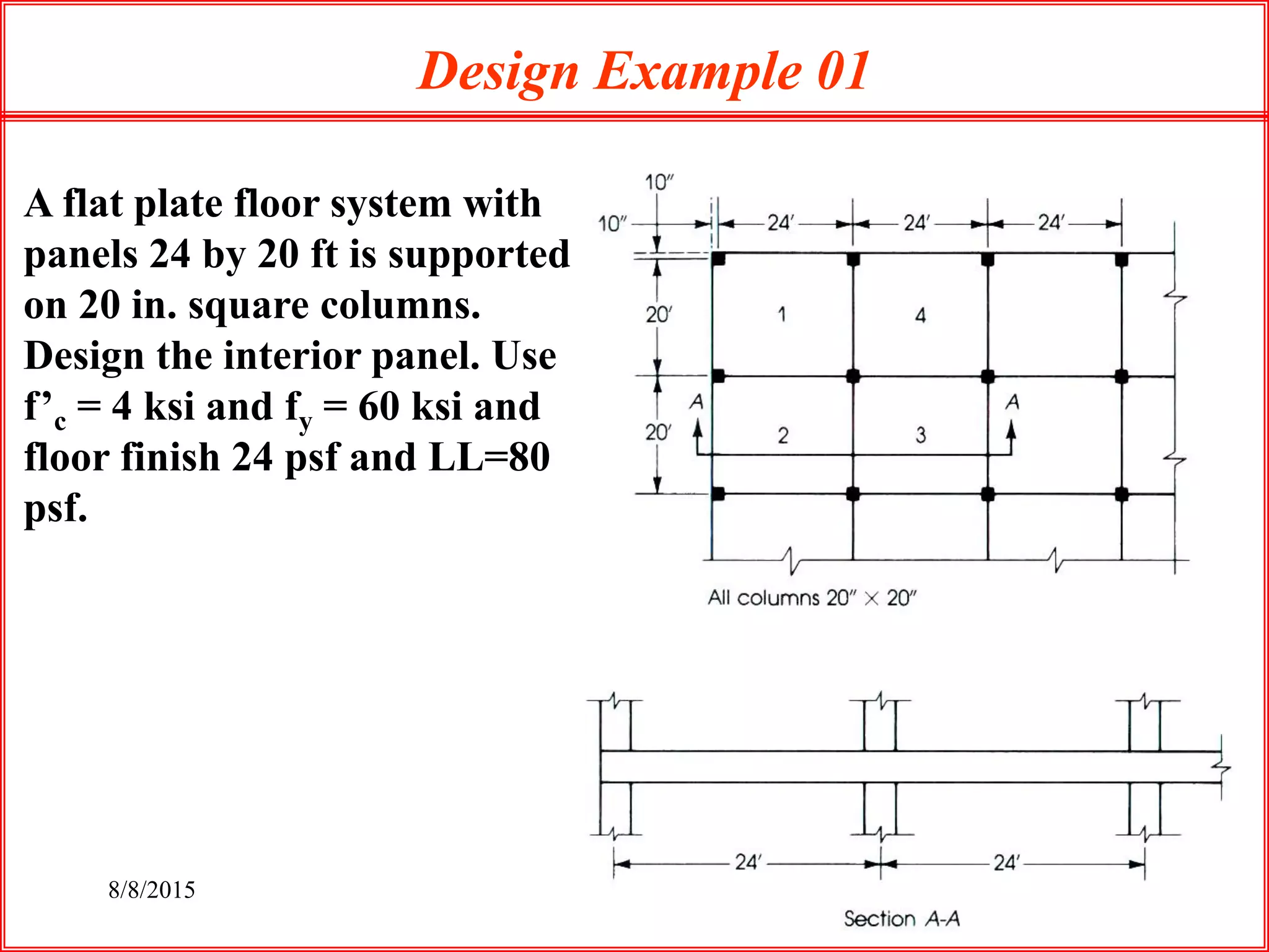
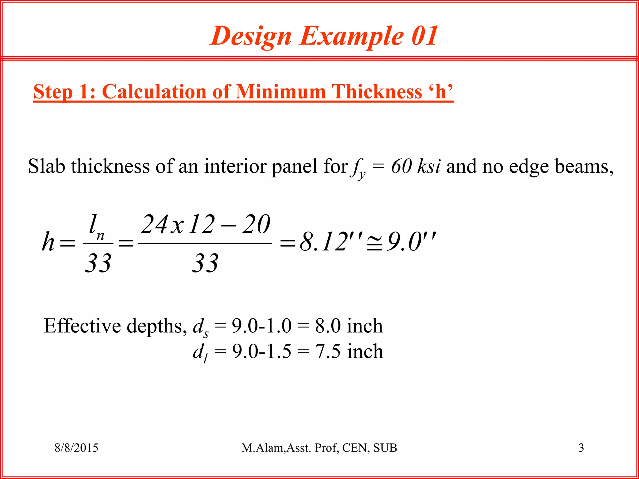
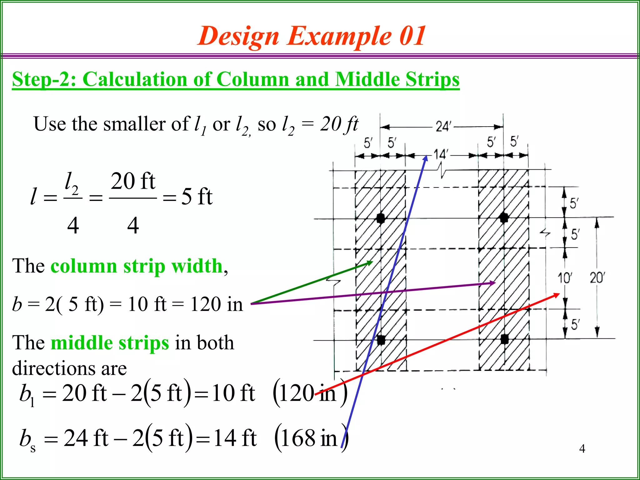
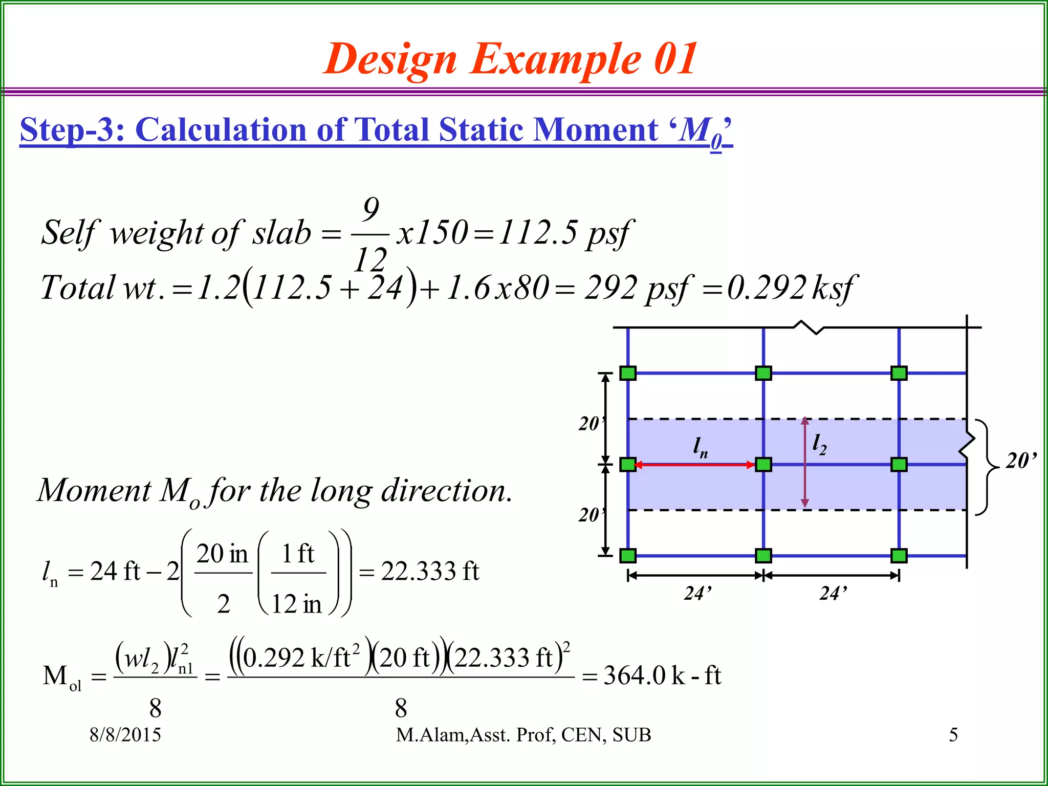
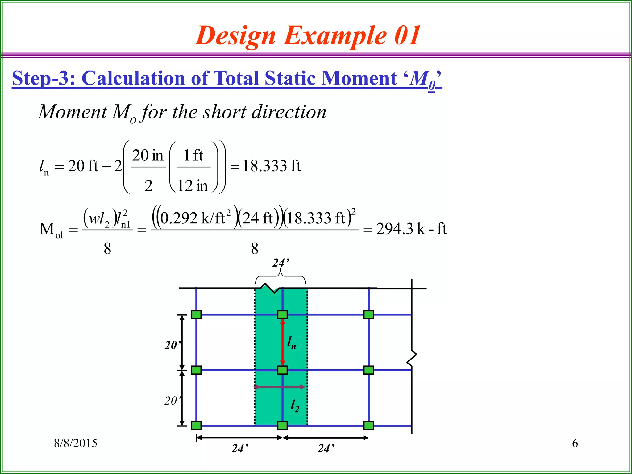
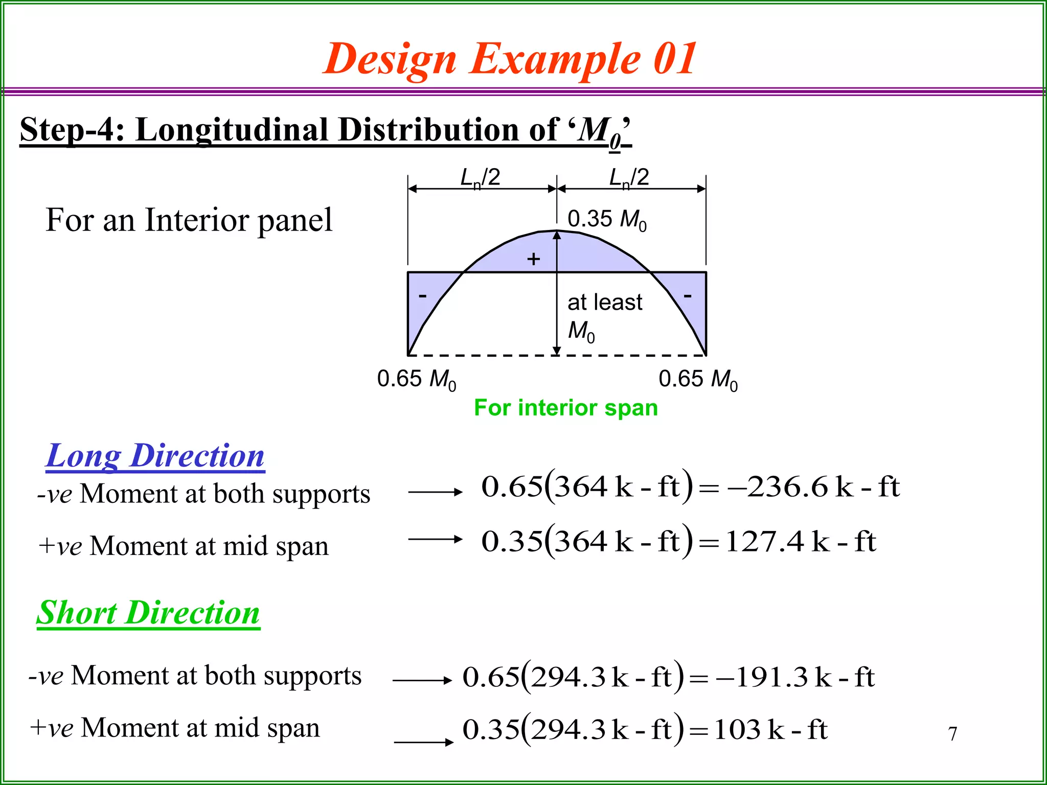
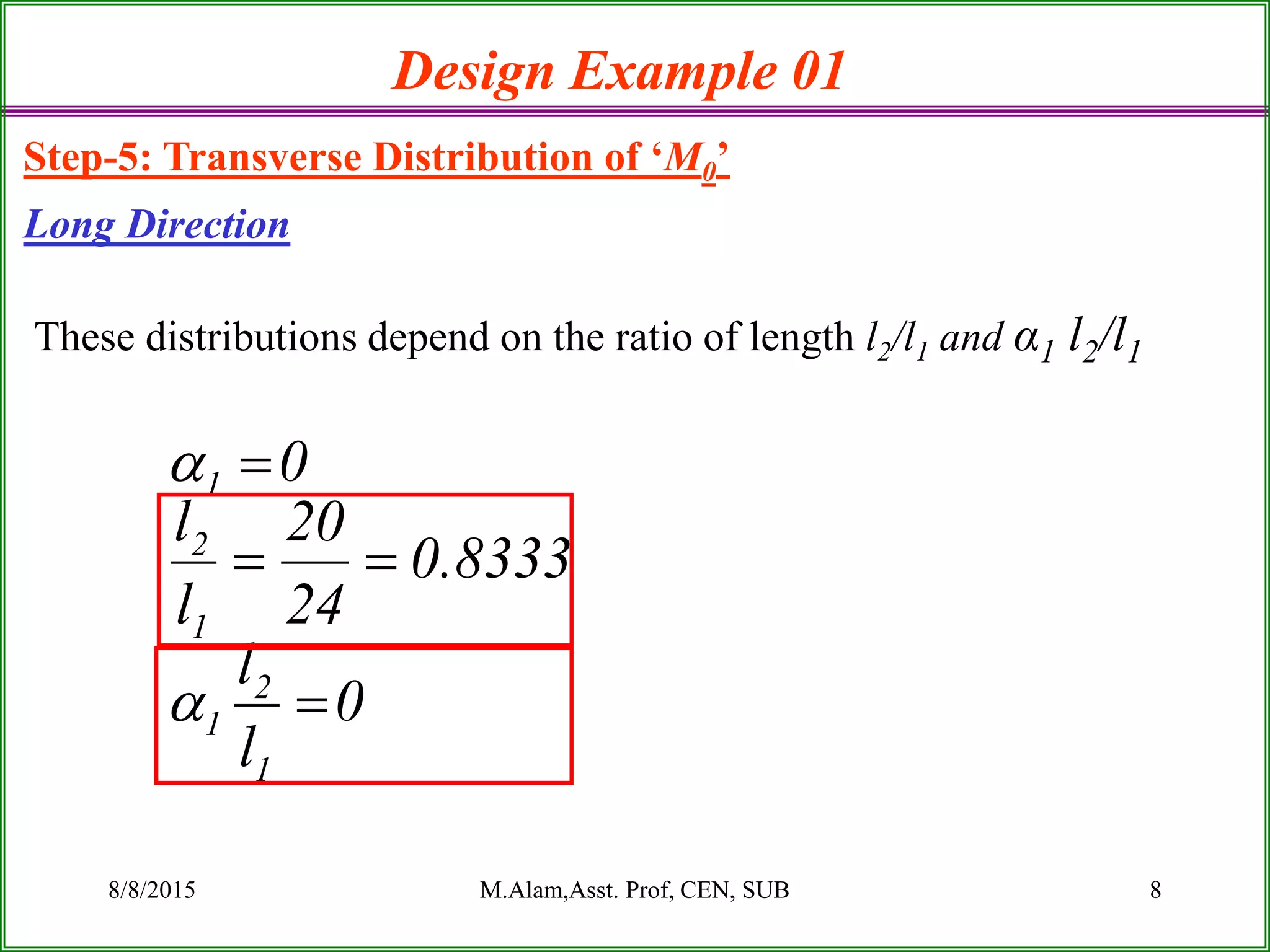
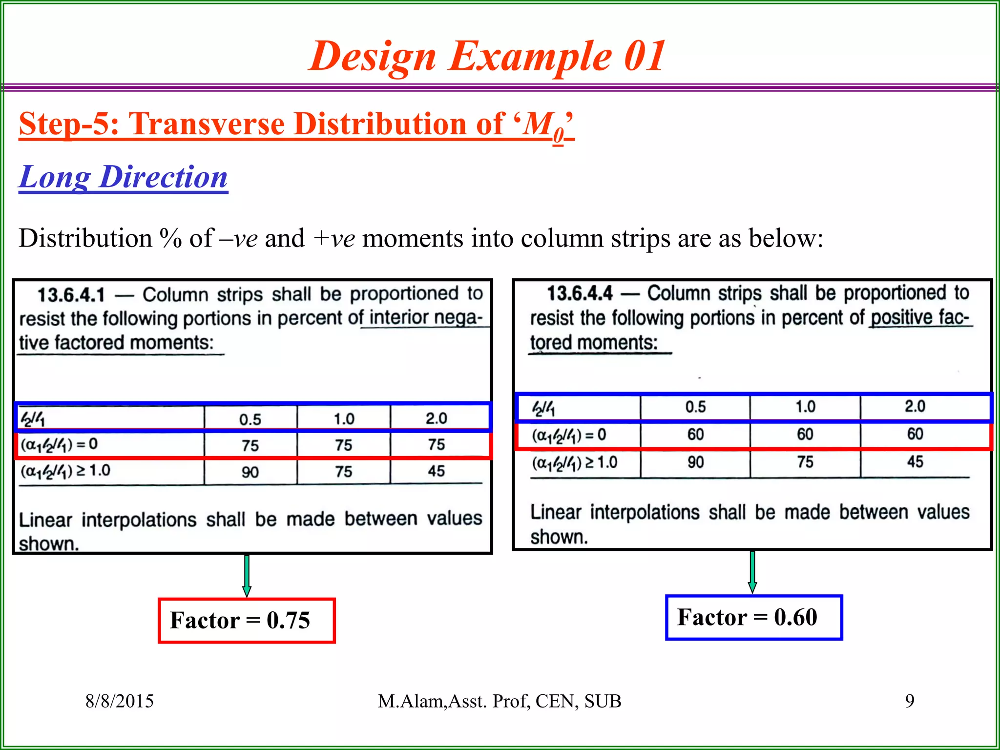
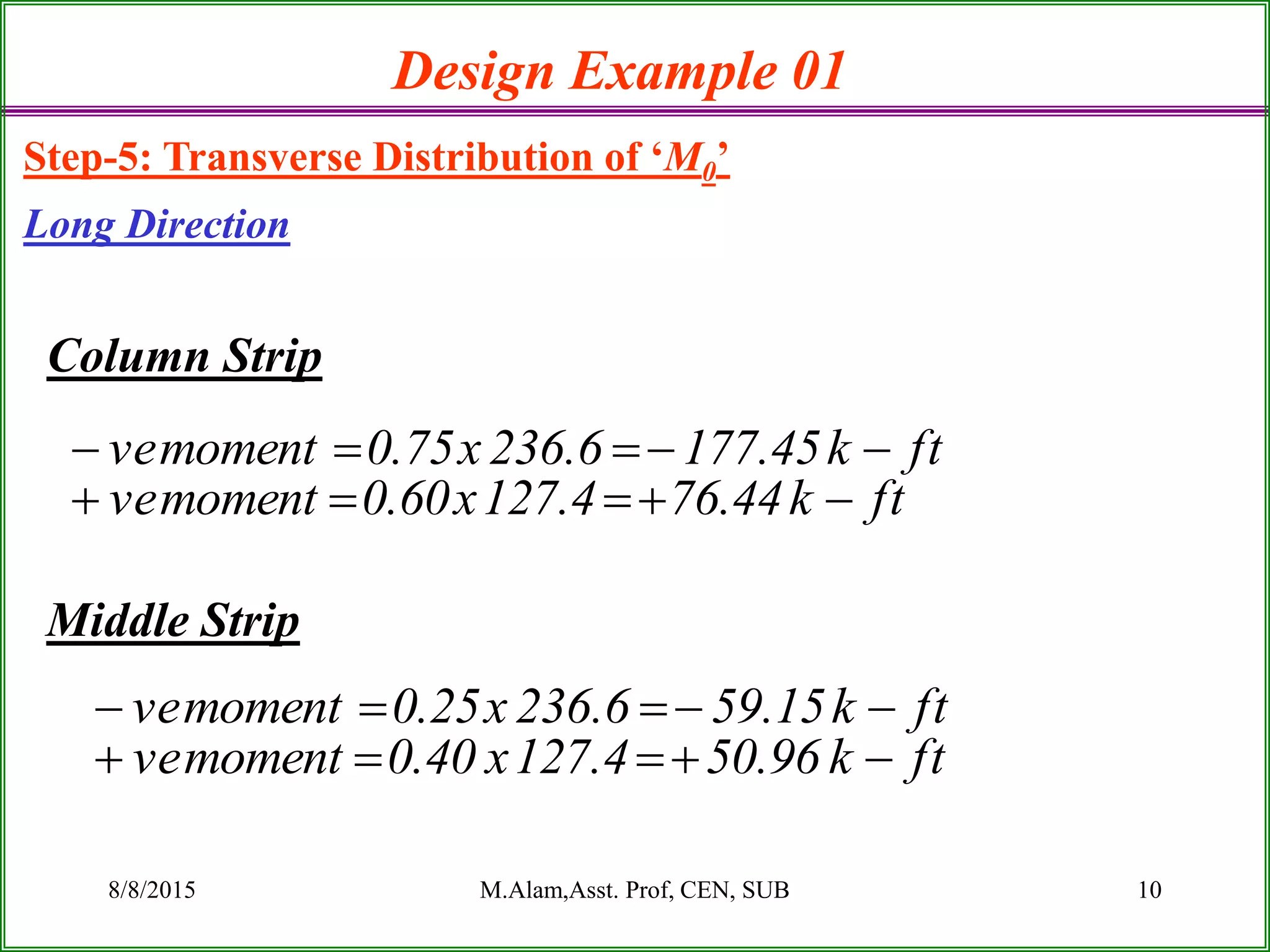
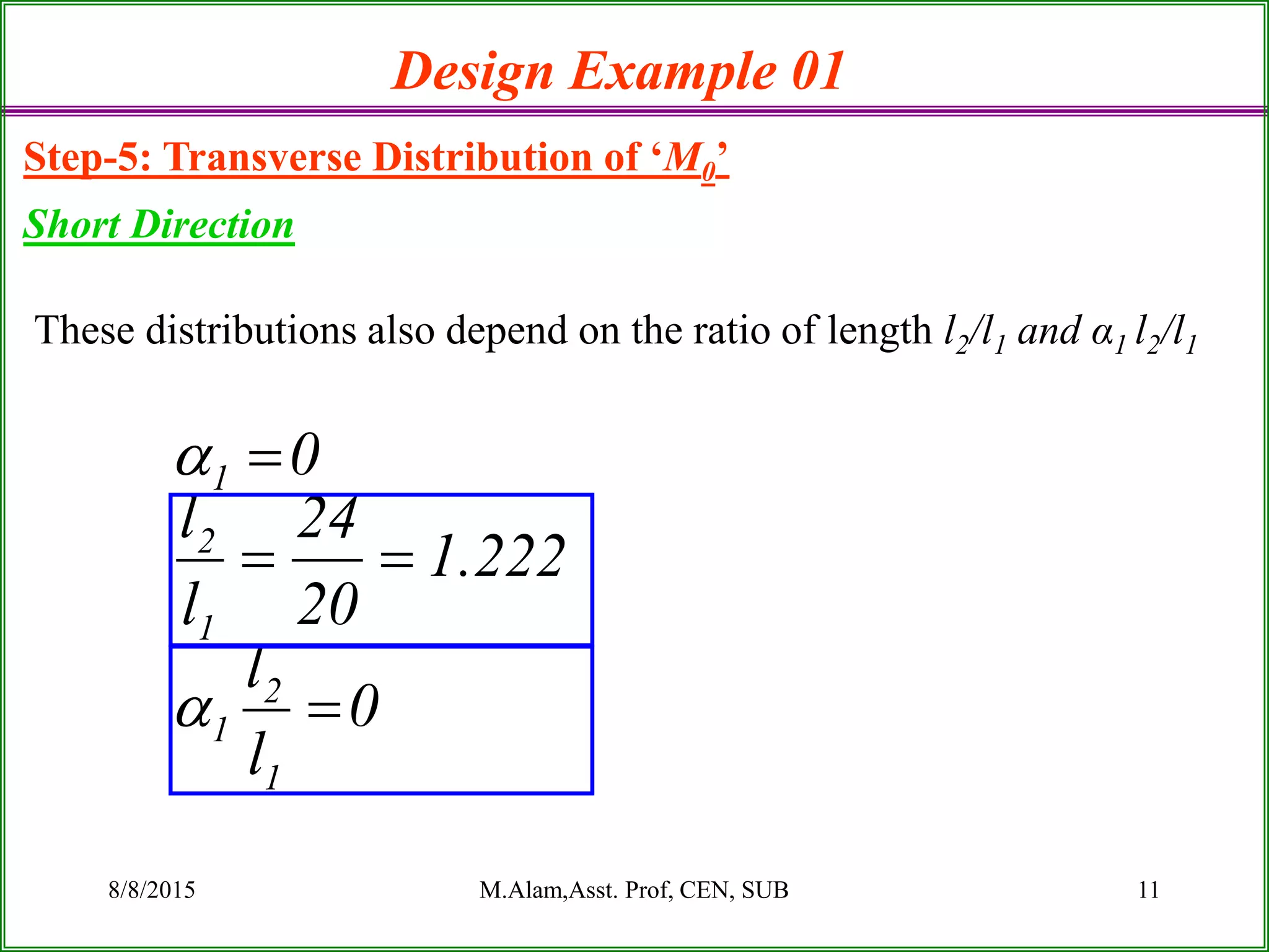
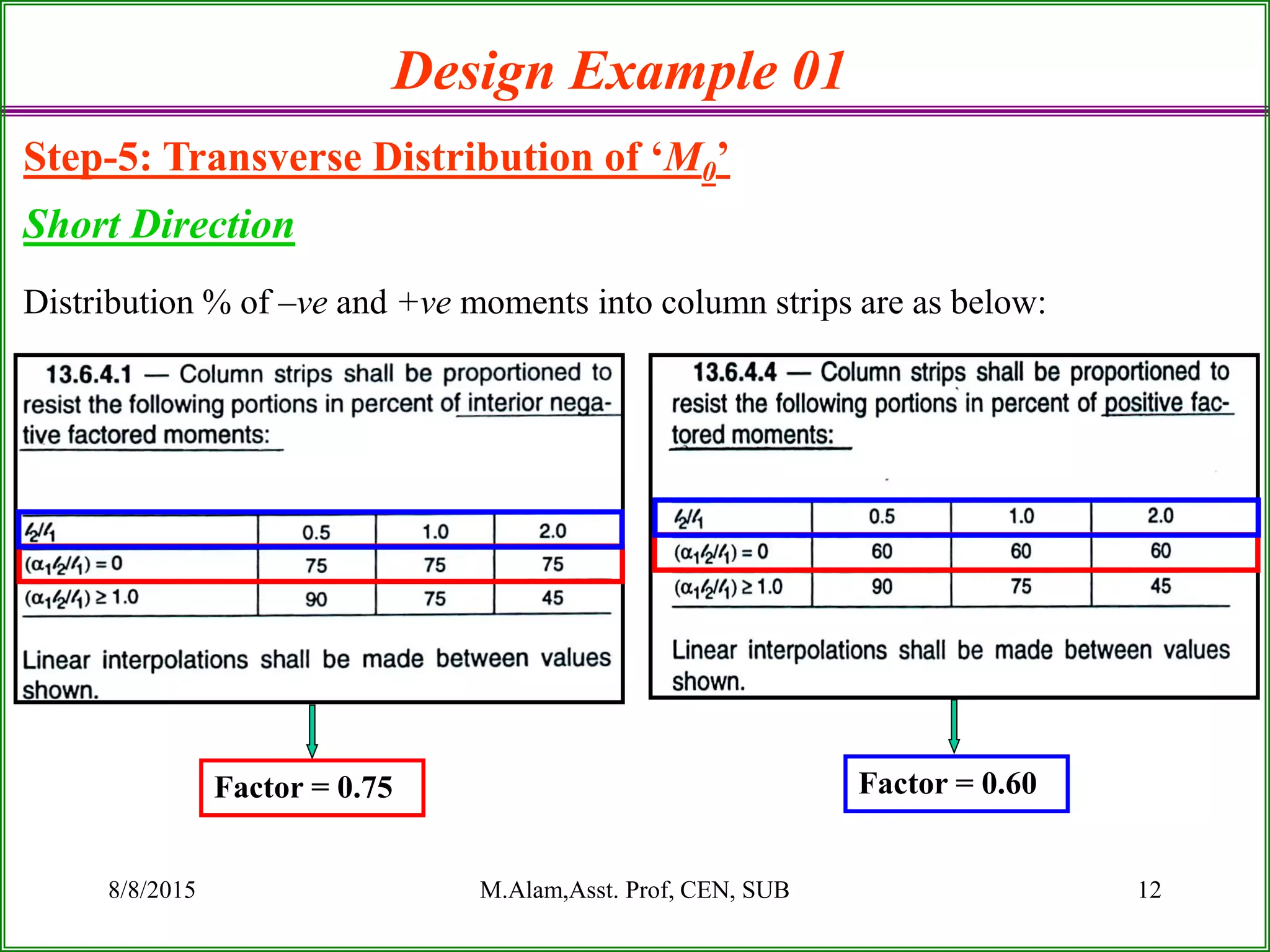
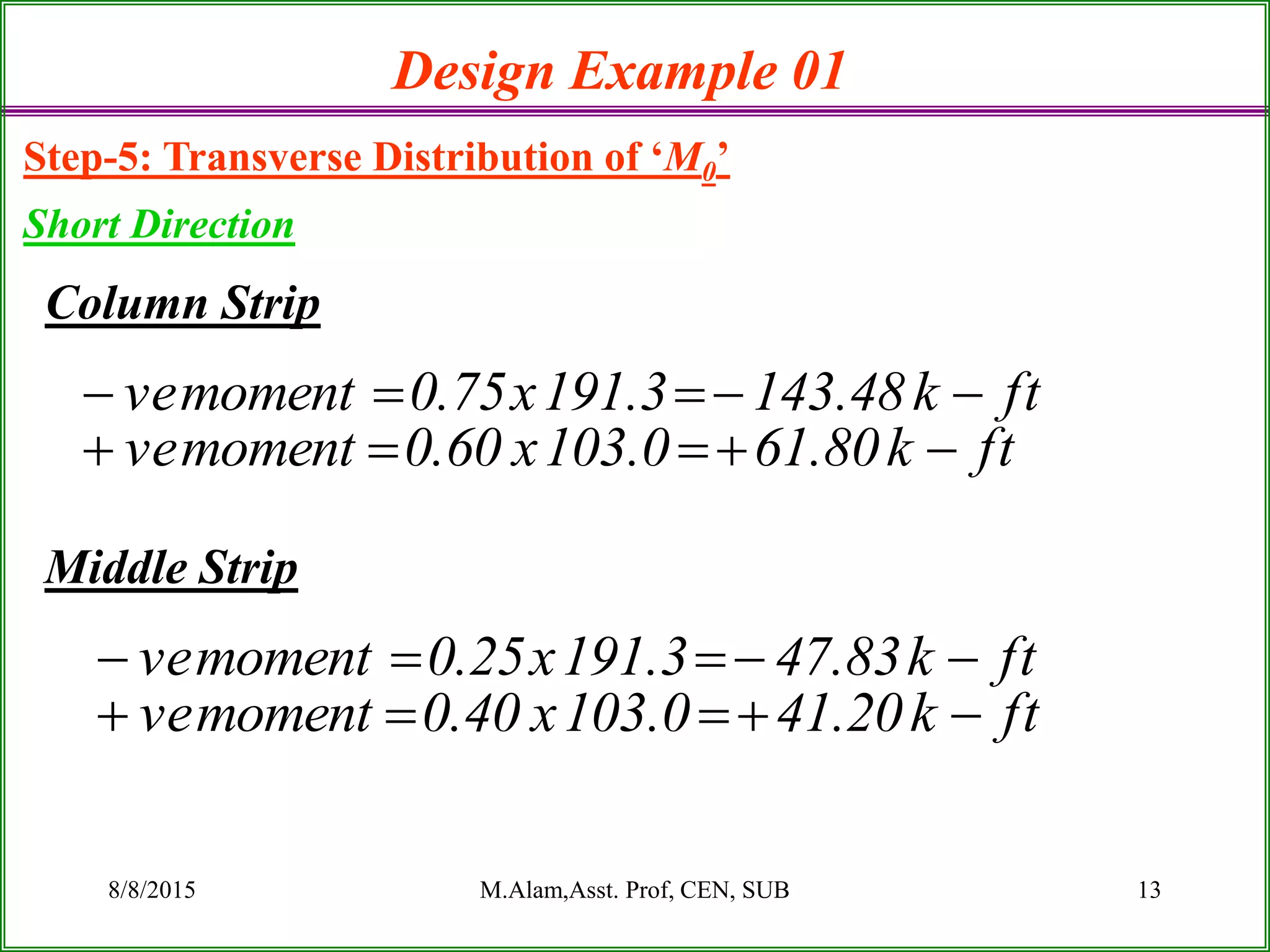
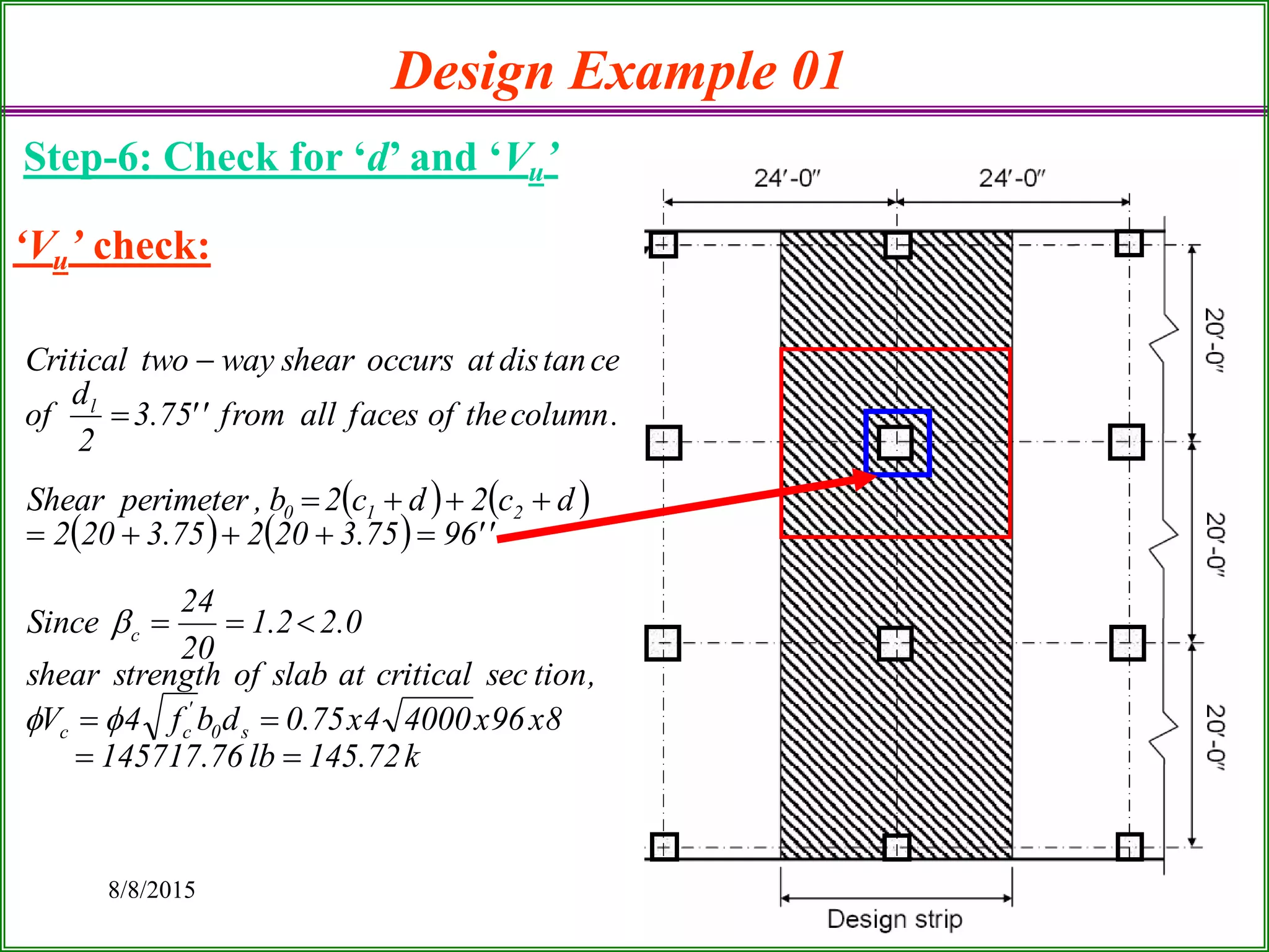
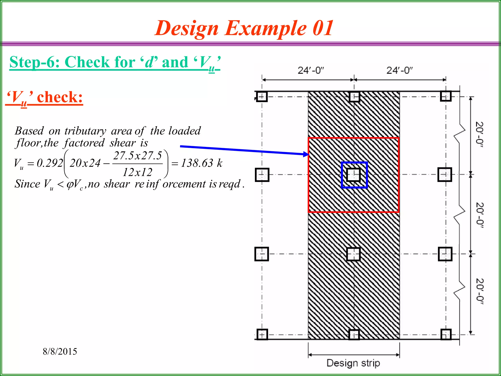
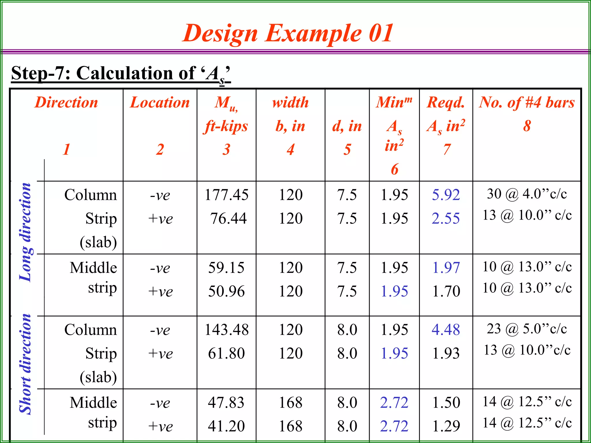
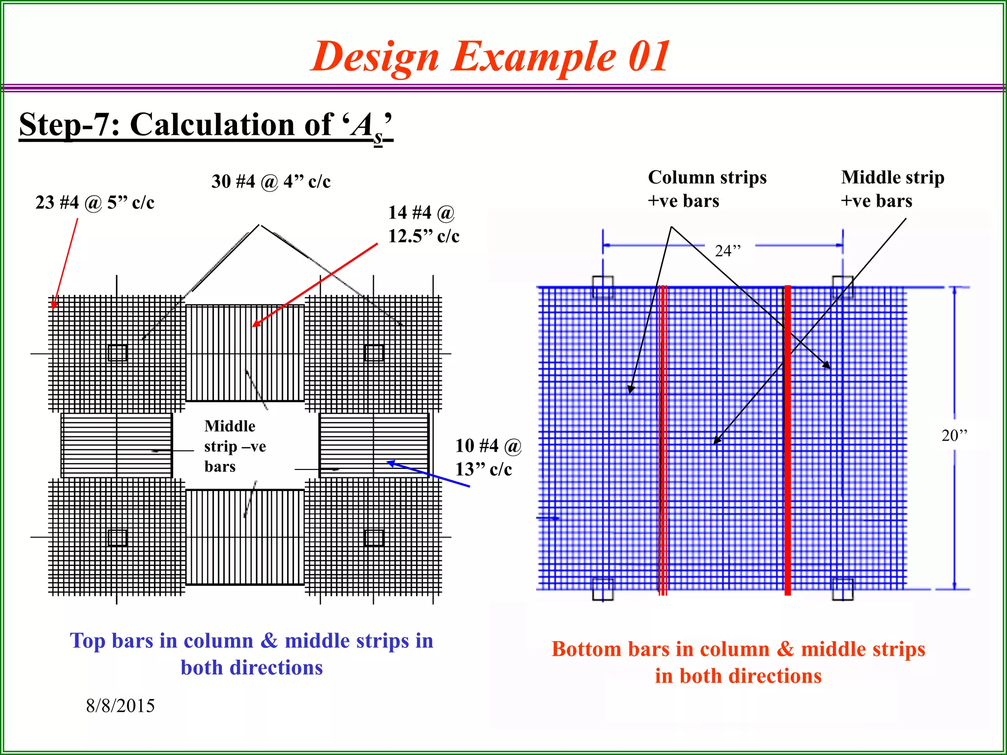
Flat Plate Slab Design for B.Sc. in Civil Engg Students
By: Md.Mahbub Ul Alam, Asst Prof, Dept. of Civil Engg.
Stamford University Bangladesh.
Uploaded at www.sladeshare.net.
Heart Disease Prediction using machine learning.pptx
Lec 3 design problem of flat plate slab
1. LECTURE 3
DESIGN PROBLEM OF FLAT PLATE SLAB
By
MD. MAHBUB-UL-ALAM
ASST. PROF, DEPT. OF CIVIL ENGG.
Stamford University Bangladesh
2. 8/8/2015 2
Design Example 01
A flat plate floor system with
panels 24 by 20 ft is supported
on 20 in. square columns.
Design the interior panel. Use
f’c = 4 ksi and fy = 60 ksi and
floor finish 24 psf and LL=80
psf.
3. 8/8/2015 M.Alam,Asst. Prof, CEN, SUB 3
Step 1: Calculation of Minimum Thickness ‘h’
Design Example 01
Slab thickness of an interior panel for fy = 60 ksi and no edge beams,
Effective depths, ds = 9.0-1.0 = 8.0 inch
dl = 9.0-1.5 = 7.5 inch
''0.9''12.8
33
2012x24
33
l
h n
4. 4
Design Example 01
Step-2: Calculation of Column and Middle Strips
Use the smaller of l1 or l2, so l2 = 20 ft
ft5
4
ft20
4
2
l
l
The column strip width,
b = 2( 5 ft) = 10 ft = 120 in
The middle strips in both
directions are
in168ft14ft52ft24
in120ft10ft52ft20
s
l
b
b
5. 8/8/2015 M.Alam,Asst. Prof, CEN, SUB 5
Design Example 01
Step-3: Calculation of Total Static Moment ‘M0’
ksf292.0psf29280x6.1245.1122.1.wtTotal
psf5.112150x
12
9
slabofweightSelf
Moment Mo for the long direction.
ft-k0.364
8
ft333.22ft20k/ft292.0
8
M
ft333.22
in12
ft1
2
in20
2ft24
222
n12
ol
n
lwl
l
24’ 24’
20’
20’
20’
l2ln
6. 8/8/2015 6
Design Example 01
Step-3: Calculation of Total Static Moment ‘M0’
Moment Mo for the short direction
ft-k3.294
8
ft333.18ft24k/ft292.0
8
M
ft333.18
in12
ft1
2
in20
2ft20
222
n12
ol
n
lwl
l
24’ 24’
20’
20’
24’
l2
ln
7. 7
Design Example 01
Step-4: Longitudinal Distribution of ‘M0’
For an Interior panel
For interior span
0.35 M0
Ln/2 Ln/2
0.65 M0 0.65 M0
at least
M0
+
- -
ft-k4.127ft-k36435.0
ft-k6.236ft-k64365.0
-ve Moment at both supports
+ve Moment at mid span
Long Direction
-ve Moment at both supports
+ve Moment at mid span
ft-k103ft-k94.3235.0
ft-k3.191ft-k94.3265.0
Short Direction
8. 8/8/2015 M.Alam,Asst. Prof, CEN, SUB 8
Design Example 01
Step-5: Transverse Distribution of ‘M0’
Long Direction
These distributions depend on the ratio of length l2/l1 and α1 l2/l1
0
l
l
8333.0
24
20
l
l
0
1
2
1
1
2
1
9. 8/8/2015 M.Alam,Asst. Prof, CEN, SUB 9
Design Example 01
Step-5: Transverse Distribution of ‘M0’
Long Direction
Distribution % of –ve and +ve moments into column strips are as below:
Factor = 0.75 Factor = 0.60
10. 8/8/2015 M.Alam,Asst. Prof, CEN, SUB 10
Column Strip
Middle Strip
Design Example 01
Step-5: Transverse Distribution of ‘M0’
Long Direction
ftk44.764.127x60.0momentve
ftk45.1776.236x75.0momentve
ftk96.504.127x40.0momentve
ftk15.596.236x25.0momentve
11. 8/8/2015 M.Alam,Asst. Prof, CEN, SUB 11
Design Example 01
Step-5: Transverse Distribution of ‘M0’
Short Direction
These distributions also depend on the ratio of length l2/l1 and α1 l2/l1
0
l
l
222.1
20
24
l
l
0
1
2
1
1
2
1
12. 8/8/2015 M.Alam,Asst. Prof, CEN, SUB 12
Design Example 01
Step-5: Transverse Distribution of ‘M0’
Short Direction
Distribution % of –ve and +ve moments into column strips are as below:
Factor = 0.75 Factor = 0.60
13. 8/8/2015 M.Alam,Asst. Prof, CEN, SUB 13
Column Strip
Middle Strip
Design Example 01
Step-5: Transverse Distribution of ‘M0’
Short Direction
ftk80.610.103x60.0momentve
ftk48.1433.191x75.0momentve
ftk20.410.103x40.0momentve
ftk83.473.191x25.0momentve
14. 8/8/2015 M.Alam,Asst. Prof, CEN, SUB 14
Design Example 01
Step-6: Check for ‘d’ and ‘Vu’
ok''0.8''39.3d
4
60x0214.0
59.01xd168x60x0214.0x90.012x48.143
''0.8d,''168b,ftk6.48.143moment.maxdirectionshortIn
ok''5.7''35.4d
4
60x0214.0
59.01xd120x60x0214.0x90.012x45.177
MM,Now
0214.0,Let
''5.7d,''120b,ftk45.177moment.maxdirectionlongIn
2
p
2
nu
max
p
‘d’ check:
15. 8/8/2015 15
Design Example 01
Step-6: Check for ‘d’ and ‘Vu’
‘Vu’ check:
k72.145lb76.145717
8x96x40004x75.0dbf4V
,tionseccriticalatslabofstrengthshear
0.22.1
20
24
Since
''9675.320275.3202
dc2dc2b,perimeterShear
.columntheoffacesallfrom''75.3
2
d
of
cetandisatoccursshearwaytwoCritical
s0
'
cc
c
210
l
16. 8/8/2015 16
Design Example 01
Step-6: Check for ‘d’ and ‘Vu’
.reqdisorcementinfreshearno,VVSince
k63.138
12x12
5.27x5.27
24x20292.0V
isshearfactoredthe,floor
loadedtheofareatributaryonBased
cu
u
‘Vu’ check:
18. 8/8/2015 18
Design Example 01
Step-7: Calculation of ‘As’
30 #4 @ 4’’ c/c
24’’
20’’
Middle
strip –ve
bars
Top bars in column & middle strips in
both directions
Bottom bars in column & middle strips
in both directions
Column strips
+ve bars
Middle strip
+ve bars23 #4 @ 5’’ c/c
10 #4 @
13’’ c/c
14 #4 @
12.5’’ c/c
19. 8/8/2015 19
Design Example 01
Step-7: Calculation of ‘As’
b
s
u
'
cy
u
s
s
A
A
barselectedoneofArea
areassteelrequiredTotal
barstotalof.no'n'where
inch18or'h2'
1n
stripofWidth
s,Spacing
trequiremensteelimummin)2
.lessiswhicheverinch18or'h2'spacingimummax)1
gconsiderincalculatedisbarsof.No
:8#Column
inchin'd'andkftinMomentMwhere
ksi4f&ksi60fwhenonly,
d4
M
A,steelrequiredTotal
:7#Column
stripmiddleorcolumnofwidthbwhere,bh0018.0AMinimum
:6#Column