Download to read offline
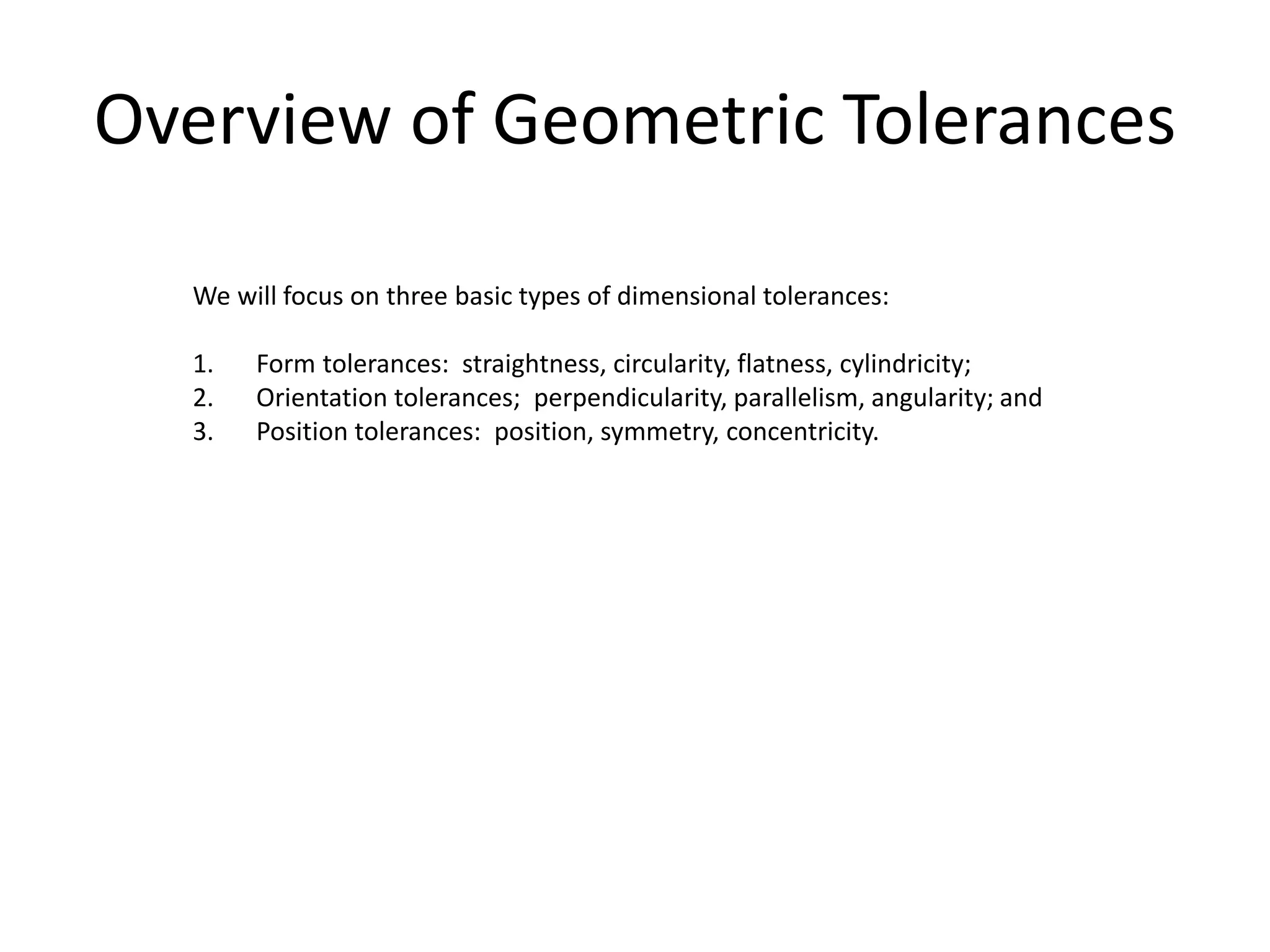
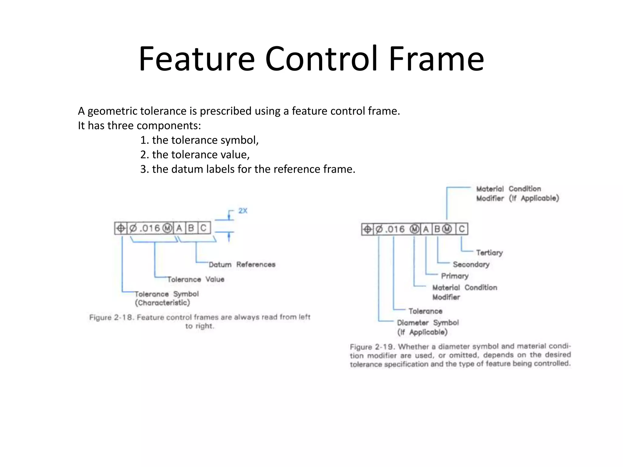
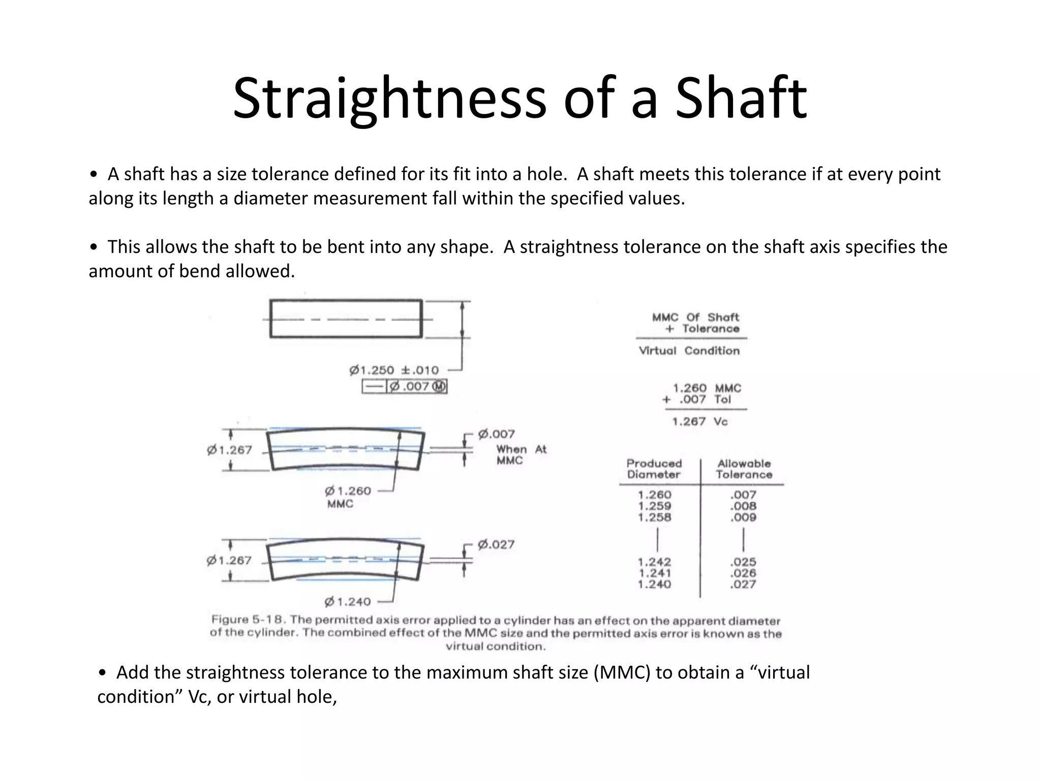
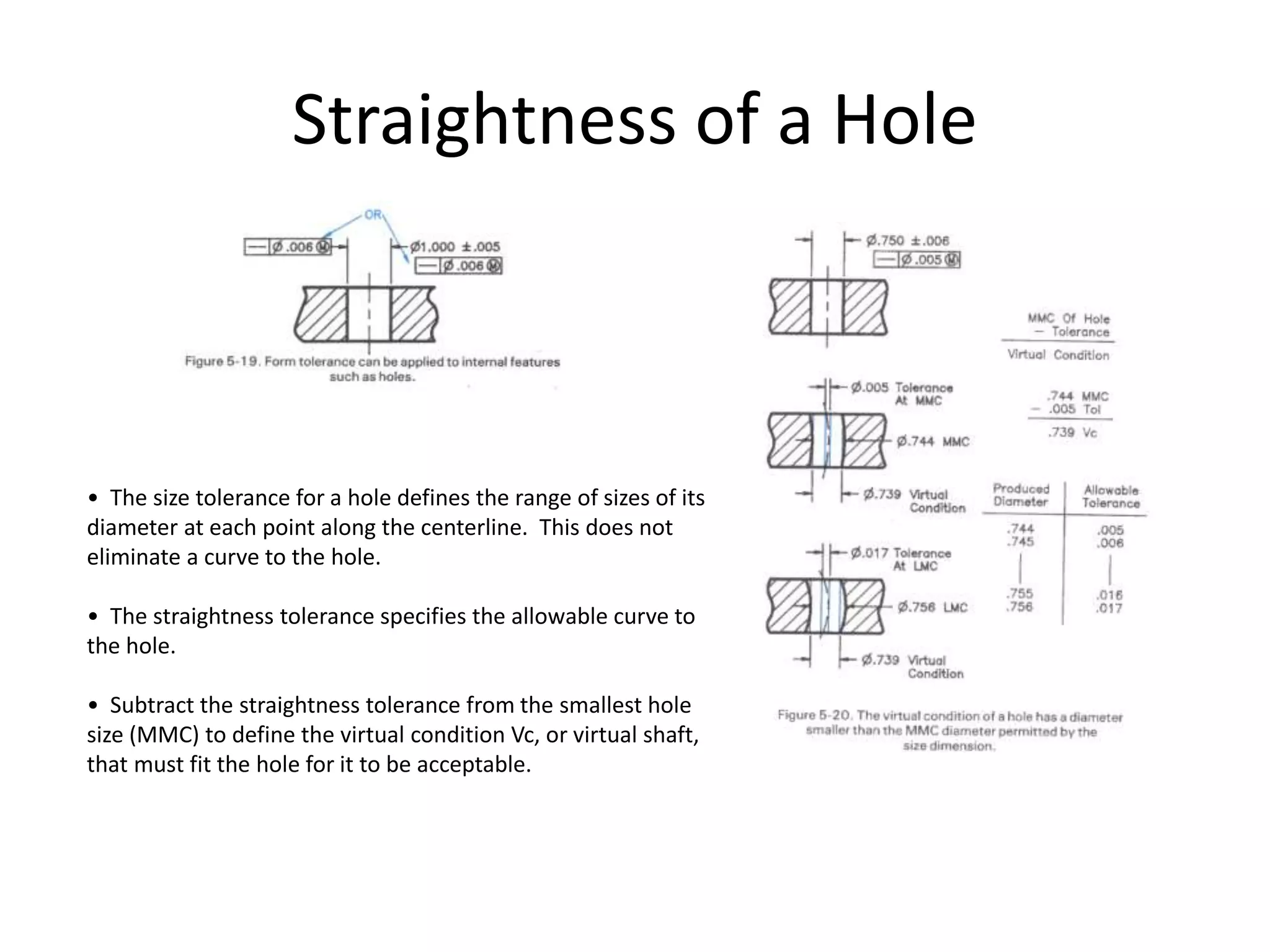
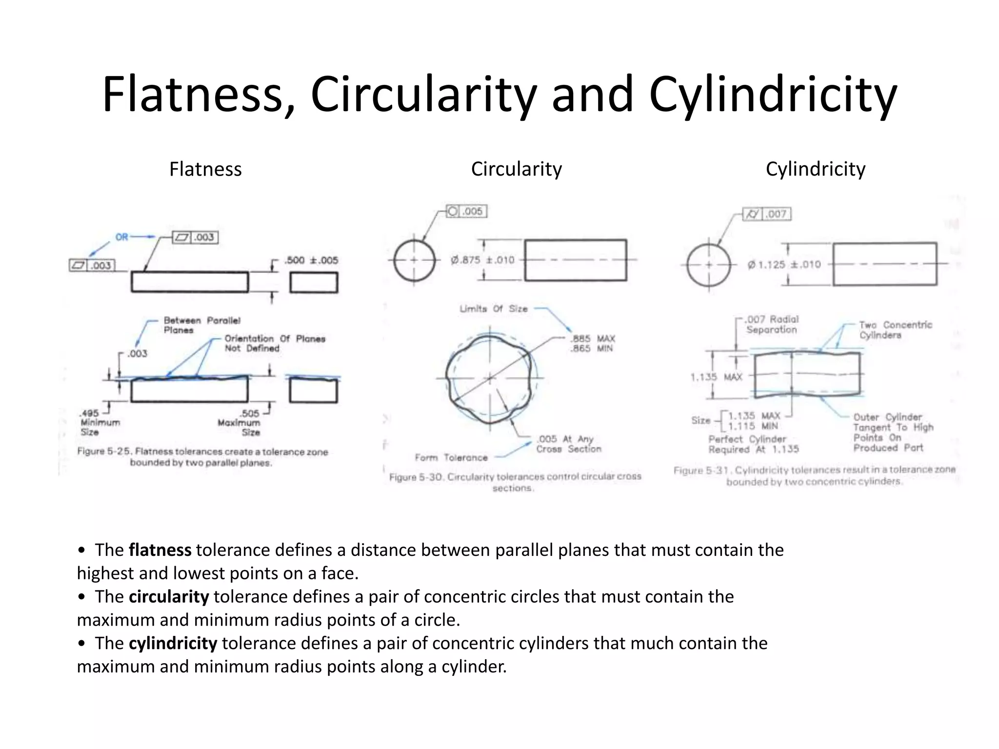
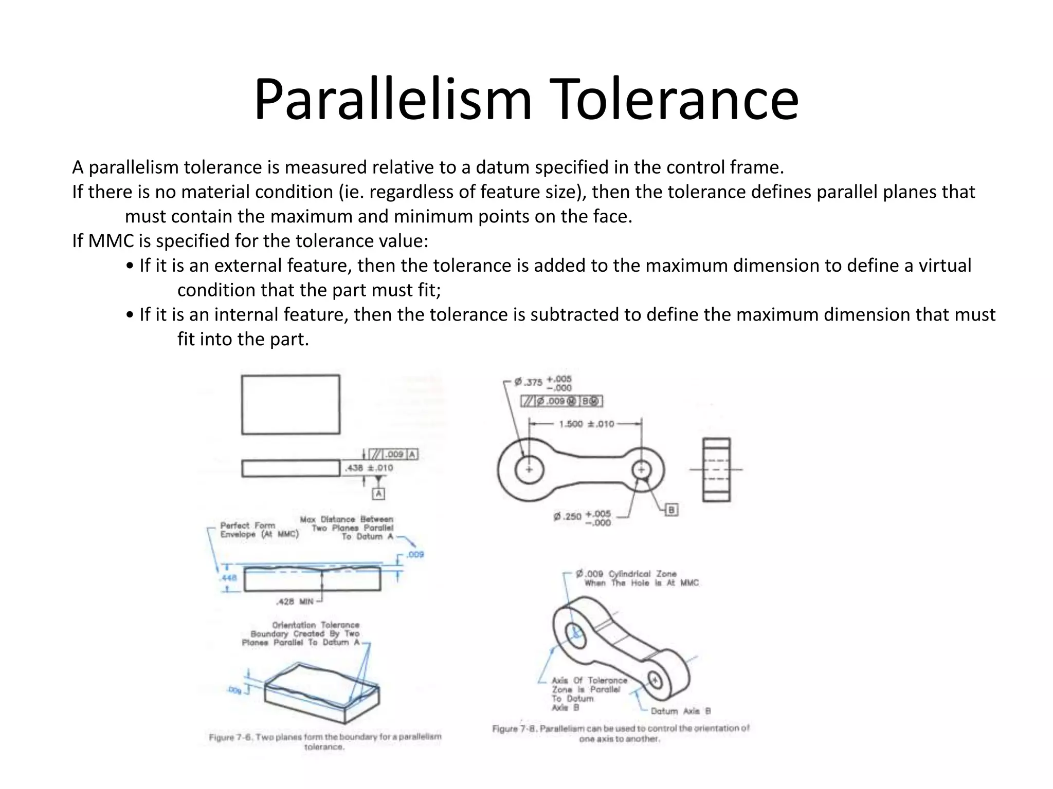
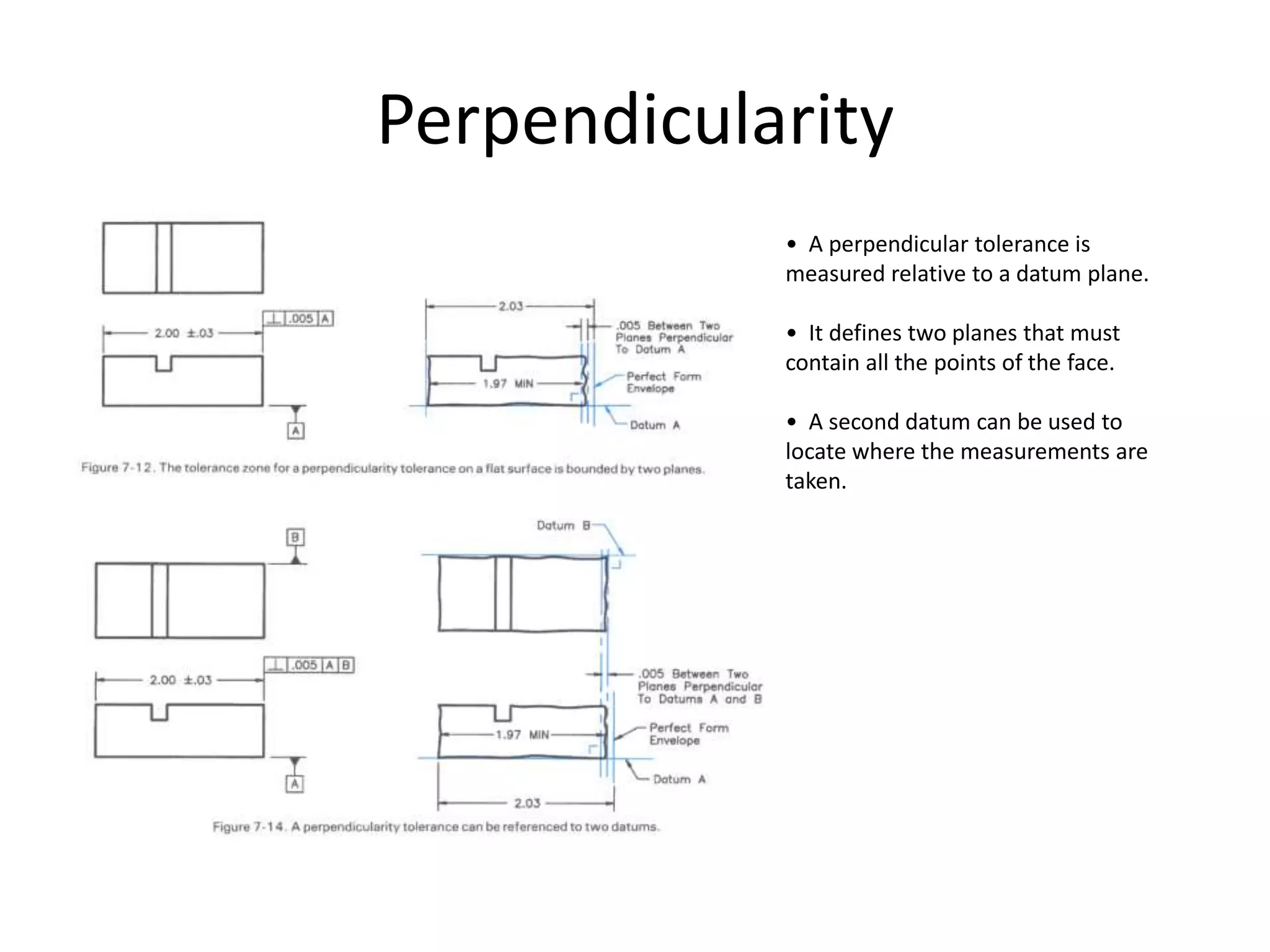
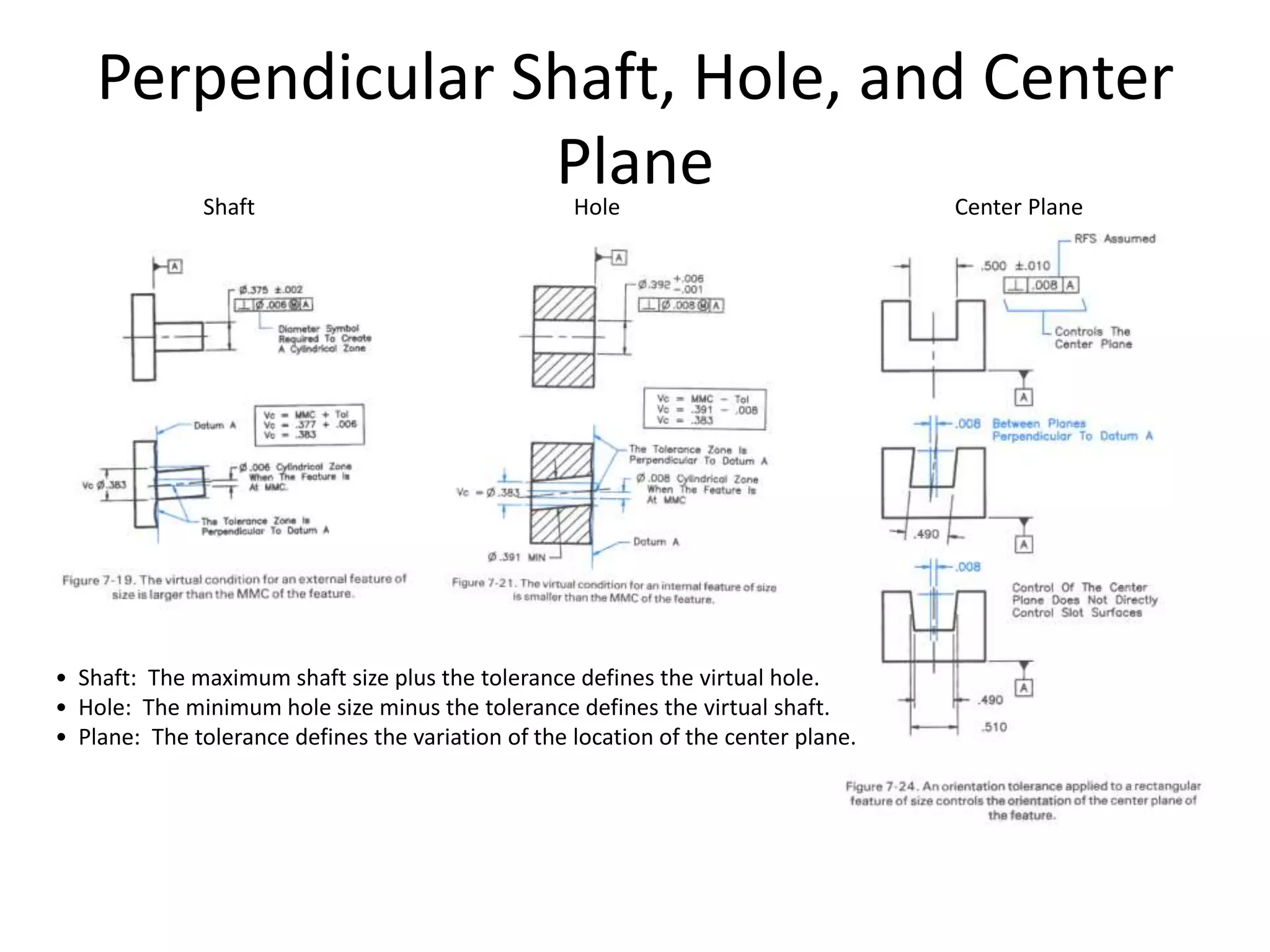
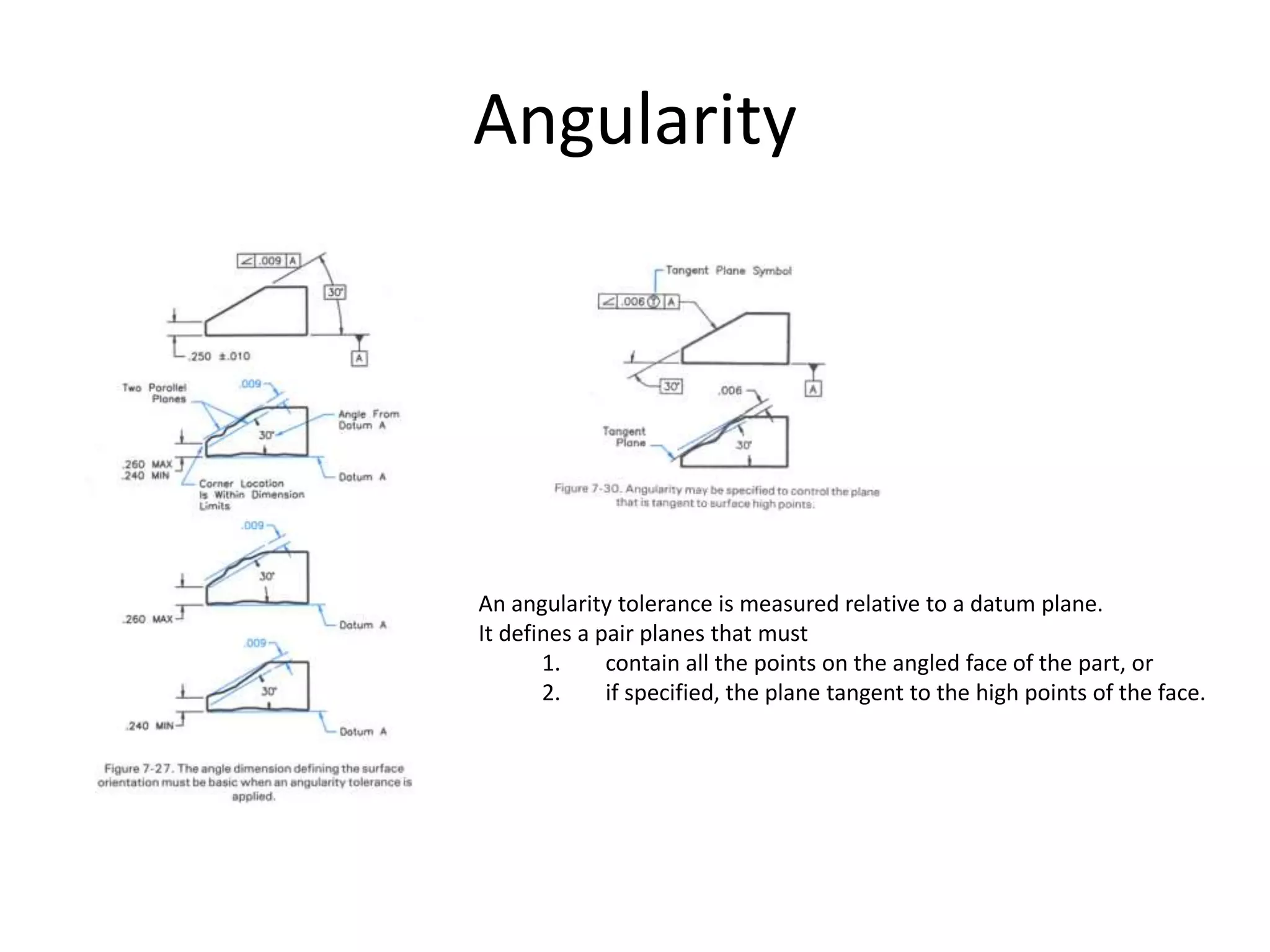
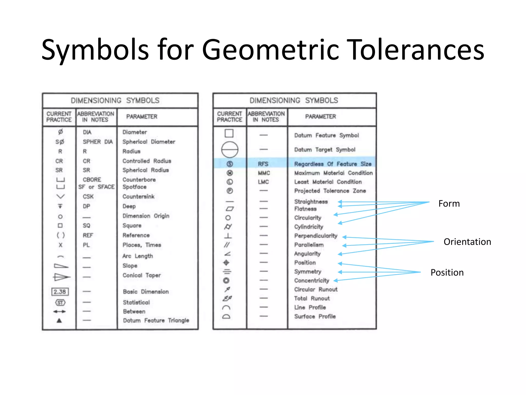

A geometric tolerance specifies the allowable variation in geometric form, orientation, or location of a feature. There are three main types of geometric tolerances: form tolerances which define straightness, circularity, flatness, or cylindricity; orientation tolerances which define perpendicularity, parallelism, or angularity; and position tolerances which define position, symmetry, or concentricity. A geometric tolerance is prescribed using a feature control frame that specifies the tolerance symbol, tolerance value, and datum references.


![Ppt Fits Tolerances[1]](https://cdn.slidesharecdn.com/ss_thumbnails/pptfitstolerances1-091107045206-phpapp01-thumbnail.jpg?width=640&height=640&fit=bounds)


