Download as PDF, PPTX


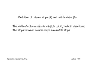


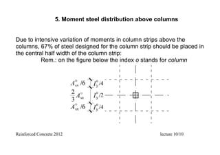

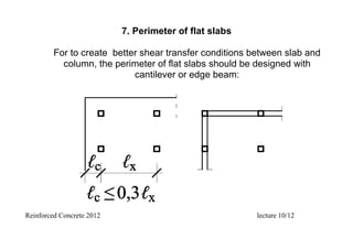


This document summarizes a lecture on flat slab design and analysis. It discusses key topics such as: 1. Definitions of flat slabs and their components like column strips and middle strips. 2. Methods of analyzing flat slabs including numerical methods and manual methods like the method of substitutive beams. 3. Design considerations for flat slabs including steel distribution above columns, welded mesh reinforcement, loading schemes, and punching shear design. 4. Different types of shear reinforcement that can be used at column heads like links, cages, and bent-up bars.


