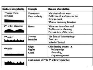
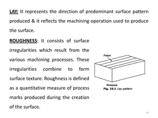
1. Surface texture is influenced by factors like machine parts functioning, load capacity, tool life, fatigue life, corrosion and wear. Irregularities on the surface arise from machine tools, cutting tools, material rupture and vibrations.
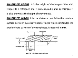
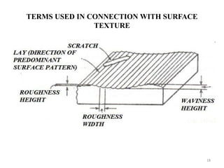
2. Surface texture is measured quantitatively to understand the effects of roughness, waviness and other irregularities. Parameters like roughness height and width, waviness height, and lay are used to characterize surface texture.
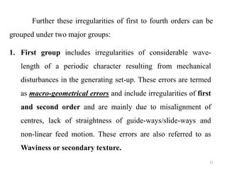
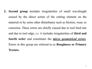
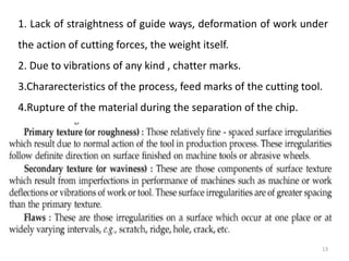
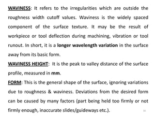
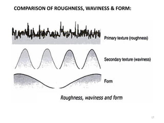
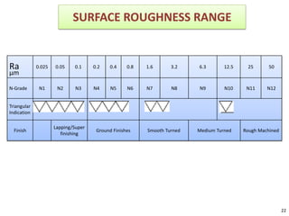
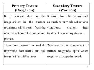
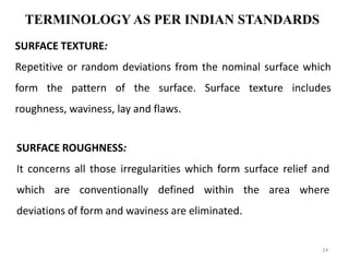
3. Surface texture includes primary texture (roughness) from production processes and secondary texture (waviness) from factors like machine deflection, vibrations and heat treatment. Different surface finishes are required for various engineering applications.