18-2
Objectives
• Interpret thesurface finish symbols that
appear on a drawing
• Use a surface finish indicator to measure the
surface finish of a part
3.
18-3
Surface Finish Measurement
•Modern technology demanding improved
surface finishes
– Often require additional operations: lapping or
honing
• System of symbols devised by ASA
– Provide standard system of determining and
indicating surface finish
– Inch unit is microinch (µin)
– Metric unit is micrometer (µm)
18-7
Surface Finish Definitions
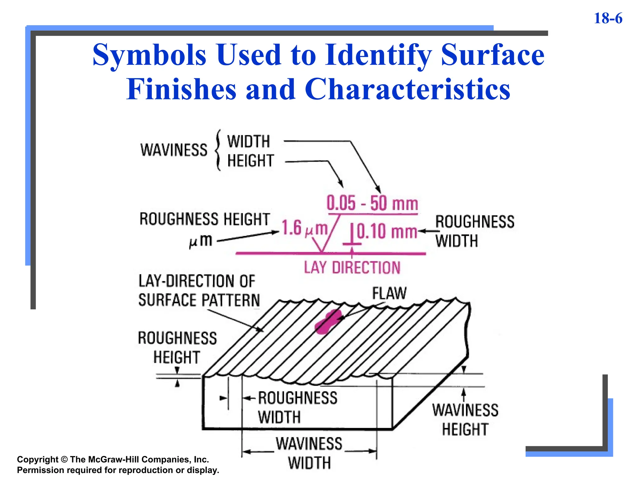
•Surface deviations: departures from nominal
surface in form of waviness, roughness, flaws, lay,
and profile
• Waviness: surface irregularities that deviate from
mean surface in form of waves
• Waviness height: peak-to-valley distance in inches
or millimeters
• Waviness width: distance between successive
waviness peaks or valleys in inches or millimeters
8.
18-8
Surface Finish Definitions
•Roughness: relatively finely spaced irregularities
superimposed on waviness pattern
– Caused by cutting tool or abrasive grain action
– Irregularities narrower than waviness pattern
• Roughness height: Ra deviation measured normal
to centerline in microinches or µm
• Roughness width: distance between successive
roughness peaks parallel to nominal surface in
inches or millimeters
• Profile: contour of specified section through a
surface
9.
18-9
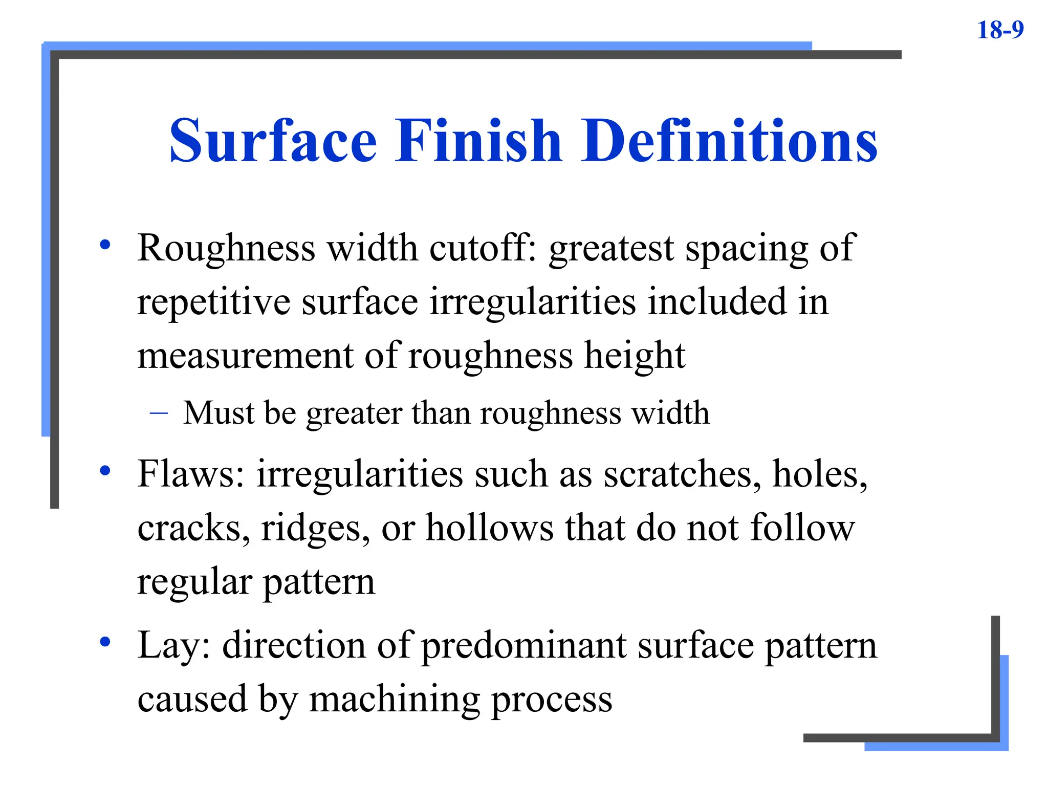
Surface Finish Definitions
•Roughness width cutoff: greatest spacing of
repetitive surface irregularities included in
measurement of roughness height
– Must be greater than roughness width
• Flaws: irregularities such as scratches, holes,
cracks, ridges, or hollows that do not follow
regular pattern
• Lay: direction of predominant surface pattern
caused by machining process
10.
18-10
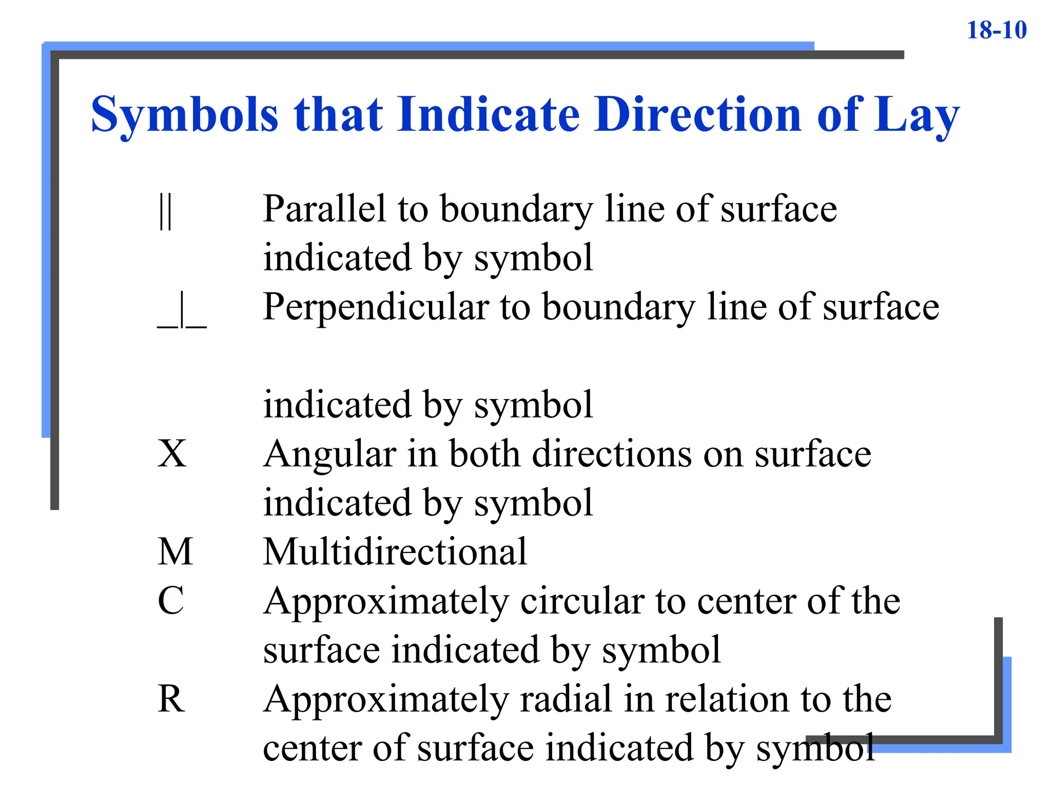
Symbols that IndicateDirection of Lay
|| Parallel to boundary line of surface
indicated by symbol
_|_ Perpendicular to boundary line of surface
indicated by symbol
X Angular in both directions on surface
indicated by symbol
M Multidirectional
C Approximately circular to center of the
surface indicated by symbol
R Approximately radial in relation to the
center of surface indicated by symbol
11.
18-11
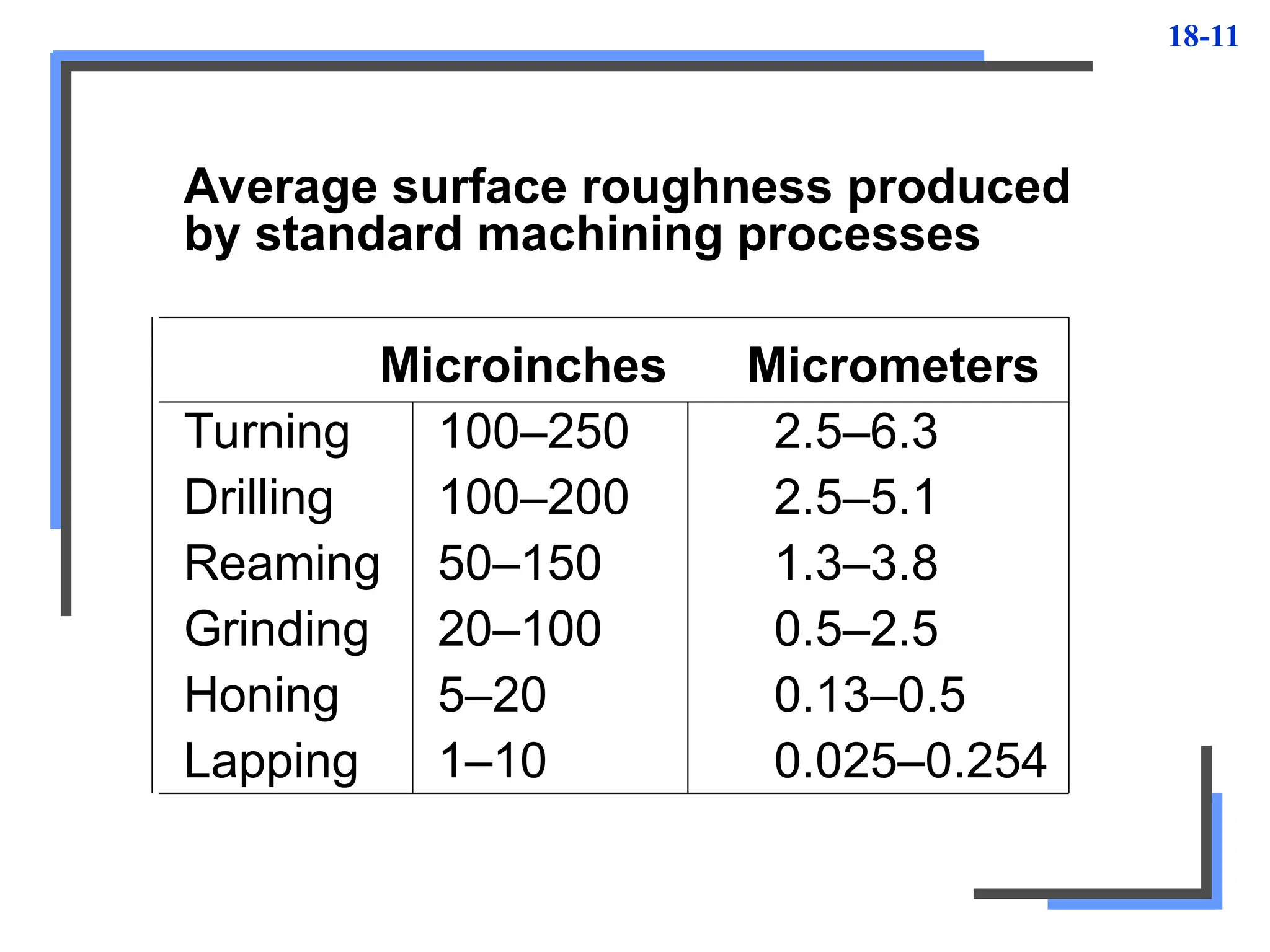
Average surface roughnessproduced
by standard machining processes
Microinches Micrometers
Turning 100–250 2.5–6.3
Drilling 100–200 2.5–5.1
Reaming 50–150 1.3–3.8
Grinding 20–100 0.5–2.5
Honing 5–20 0.13–0.5
Lapping 1–10 0.025–0.254
12.
18-12
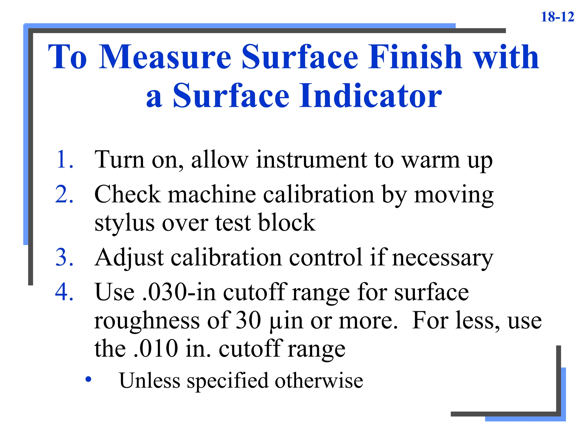
To Measure SurfaceFinish with
a Surface Indicator
1. Turn on, allow instrument to warm up
2. Check machine calibration by moving
stylus over test block
3. Adjust calibration control if necessary
4. Use .030-in cutoff range for surface
roughness of 30 µin or more. For less, use
the .010 in. cutoff range
• Unless specified otherwise
13.
18-13
To Measure SurfaceFinish with
a Surface Indicator
5. Thoroughly clean surface to be measured
• Ensures accurate readings
• Reduces wear on rider cap protecting stylus
6. Using smooth, steady movement of stylus,
trace work surface at approximately
.125 in./s
7. Note reading from meter scale
14.
18-14
Other Methods
• Surfaceanalyzer
– Uses recording device to reproduce surface
irregularities on graduated chart, providing
ink-line record
• Comparison blocks
– Used for comparing finish on workpiece with
calibrated finish on test block using fingernail
test
• Commercial sets of standard finished
specimens
– Up to 25 different surface finish samples