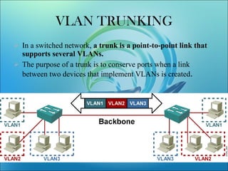
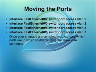
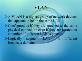
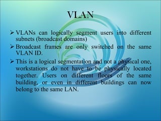
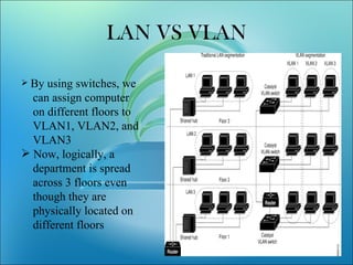
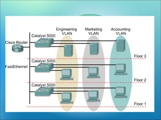
VLANs logically segment LANs into broadcast domains by using switches to assign ports and their attached devices to VLAN groups based on their MAC address, IP subnet, or switch port. This allows devices that are physically located on different floors or buildings to belong to the same logical LAN segment while preventing Layer 2 broadcasts from crossing VLAN boundaries. VLAN trunk links between switches allow multiple VLANs to be transmitted over the same physical link.


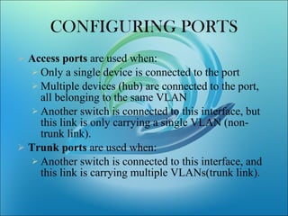
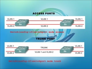
![Switch(config-if)switchport mode [access|trunk] An access port means that the port (interface) can only belong to a single VLAN.](https://image.slidesharecdn.com/vlanlatest-111228025718-phpapp02/85/Vlan-11-320.jpg)