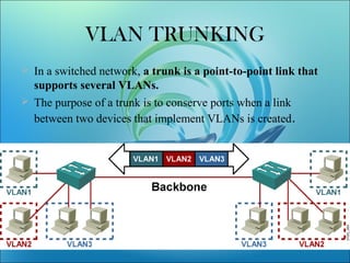
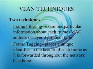
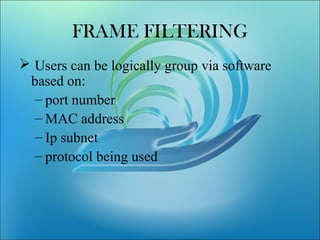
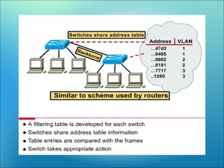
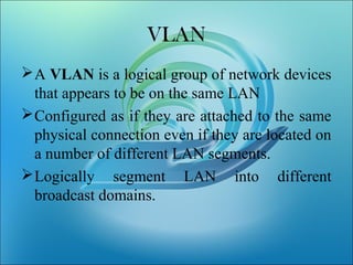
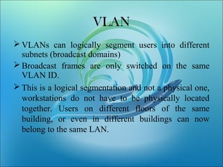
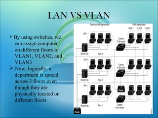
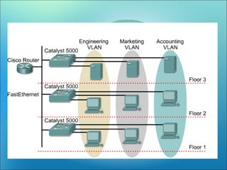
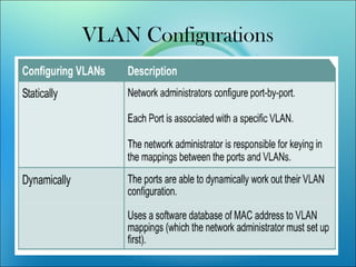
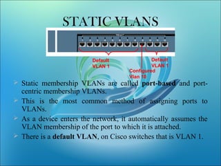
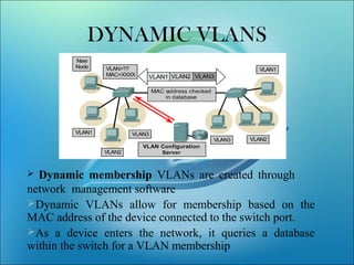
A VLAN allows computers on different physical LAN segments to communicate as if they were on the same LAN. VLANs logically segment LANs into different broadcast domains by using frame tagging to identify which VLAN a frame belongs to. There are two main types of VLAN configurations - static, where ports are manually assigned to VLANs, and dynamic, where assignments are made via network management software based on device MAC addresses.


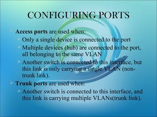
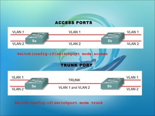
![• Switch(config-if)switchport mode
[access|trunk]
• An access port means that the port
(interface) can only belong to a single
VLAN.](https://image.slidesharecdn.com/vlanlatest-111228025718-phpapp02-171022140150/85/VLAN-Virtual-Area-Network-Switch-Ethernet-VIkram-Snehi-11-320.jpg)