Downloaded 249 times

![An example a comparator in VHDL VHDL 1. ver.8a The comparator chip: eqcomp4 a3 a2 a1 a0 equals b3 b2 b1 b0 equals VHDL for programmable logic , Skahill, Addison Wesley A=[a3,a2,a1,a0] B=[b3,b2,b1,b0]](https://image.slidesharecdn.com/vhdl1-090428004955-phpapp01/85/VHDL-Entity-5-320.jpg)


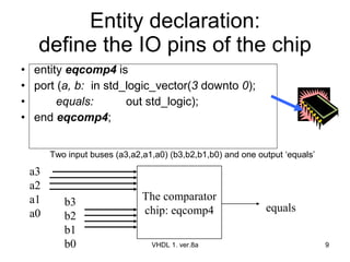


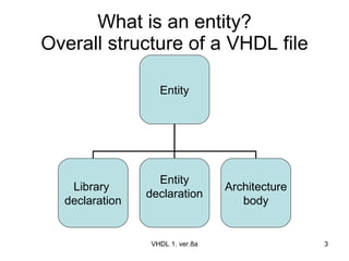
The document discusses VHDL entity declaration and architecture bodies. It explains that an entity declaration defines the input and output pins of a design, while an architecture body defines the functional implementation or operation of the design. An example comparator entity and architecture are provided to illustrate how inputs, outputs, and the comparison logic are defined. User-defined names are underlined.