Download to read offline
![Entity Declaration
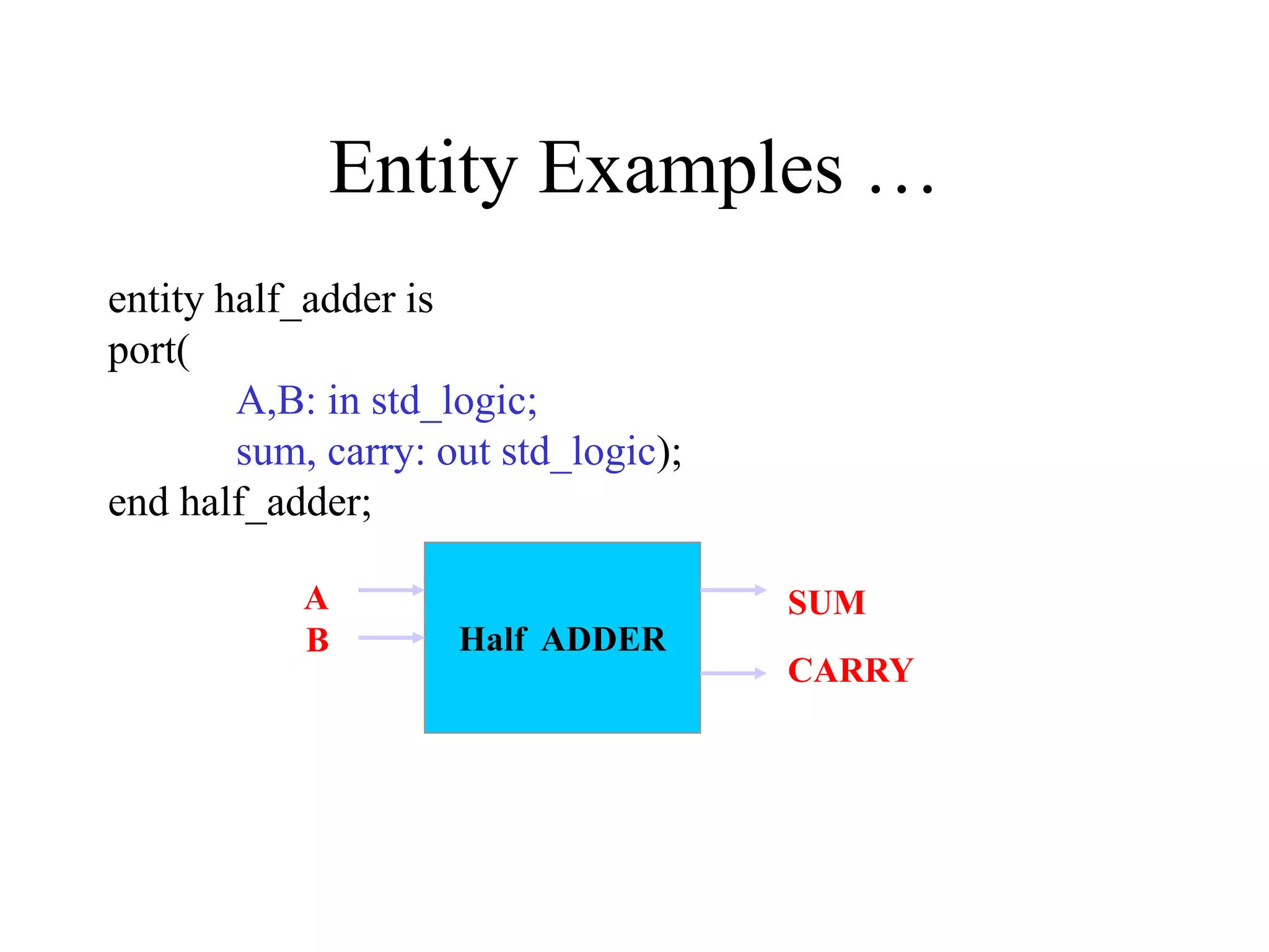
entity NAME_OF_ENTITY is
port (signal_names: mode type;
signal_names: mode type;
:
signal_names: mode type);
end [NAME_OF_ENTITY] ;
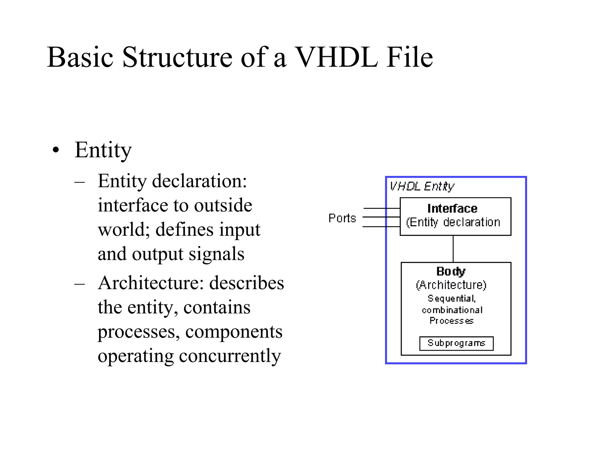
• NAME_OF_ENTITY: user defined
• signal_names: list of signals (both input and
output)
• mode: in, out, buffer, inout
• type: boolean, integer, character, std_logic](https://image.slidesharecdn.com/vhdlnew-191116081718/75/Vhdl-new-16-2048.jpg)


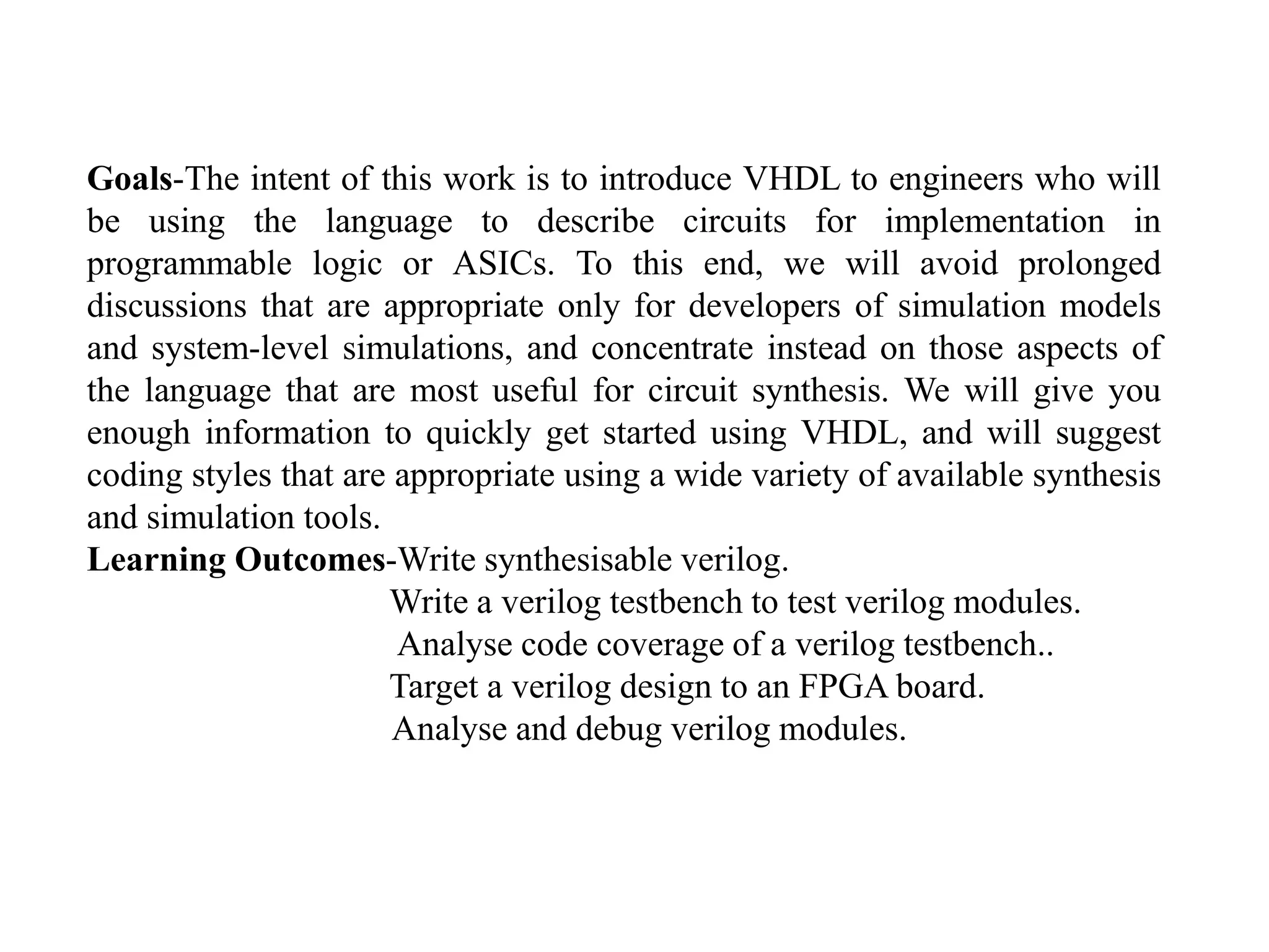
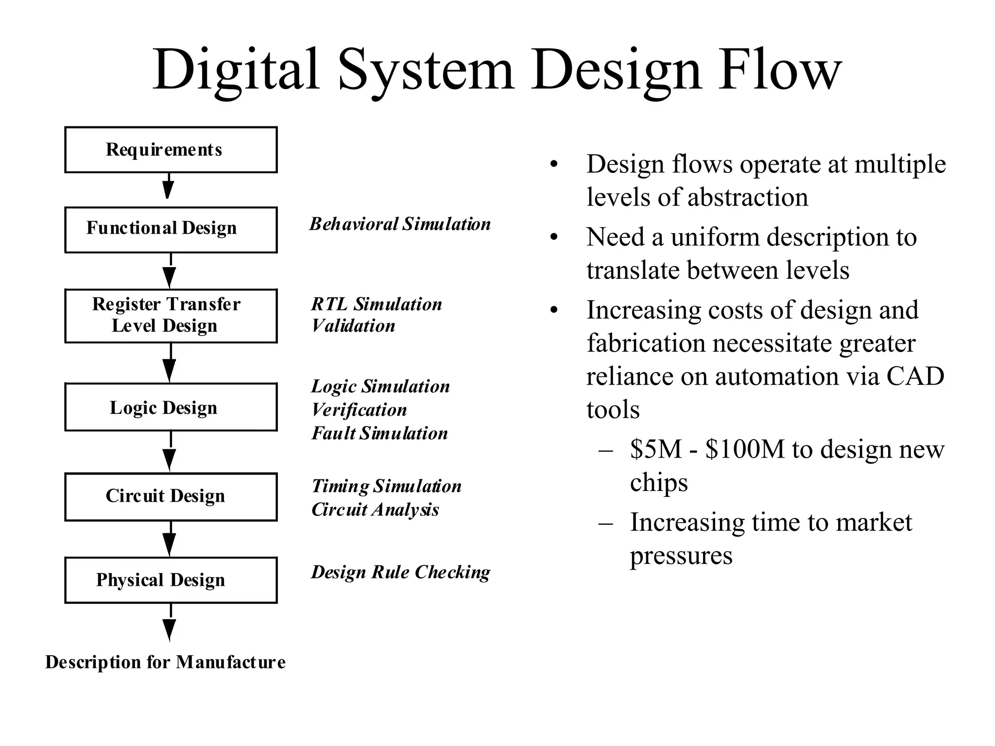
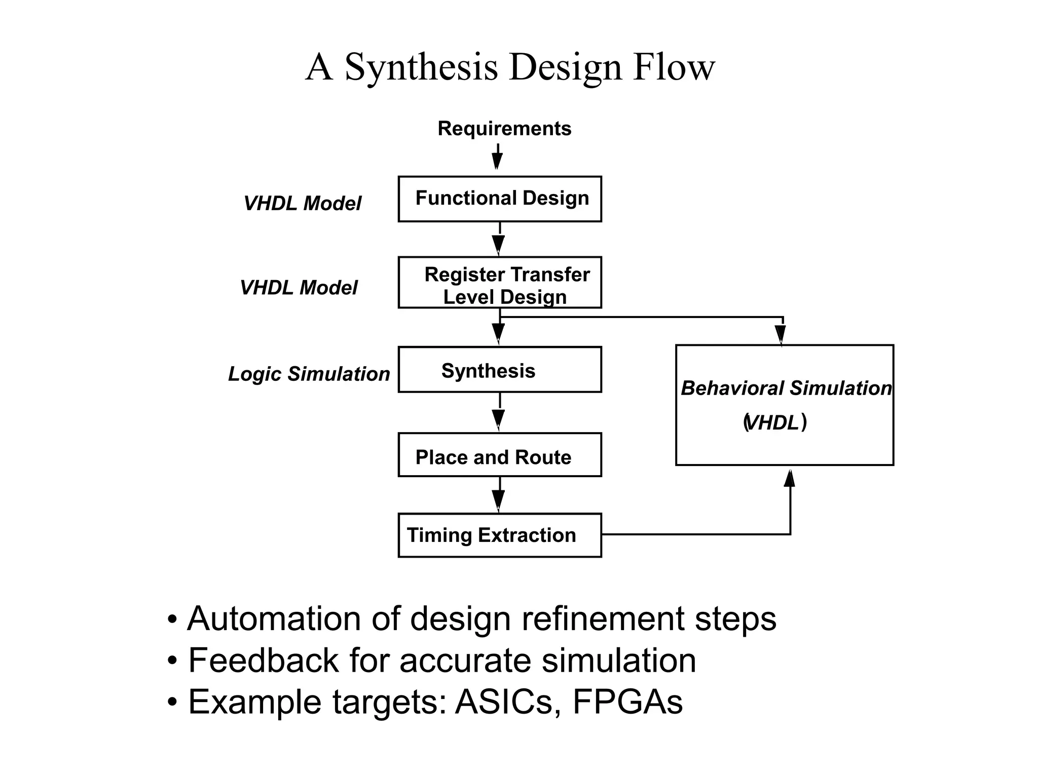
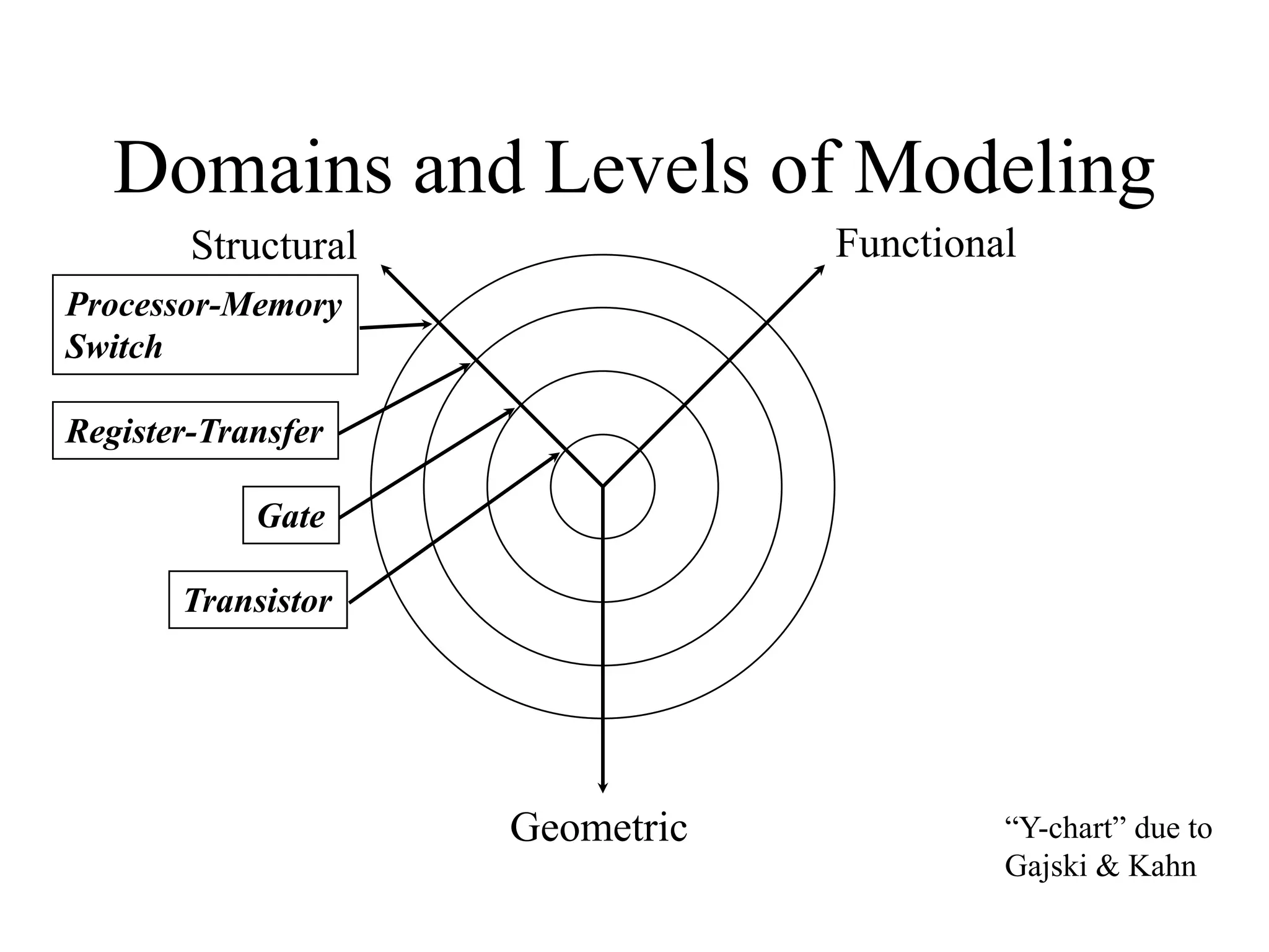
The document introduces VHDL to engineers who will use it to describe circuits for implementation in programmable logic or ASICs. It aims to provide enough information for engineers to quickly get started using VHDL while avoiding prolonged discussions more relevant for simulation developers. The document suggests coding styles appropriate for a variety of synthesis and simulation tools.