Downloaded 156 times
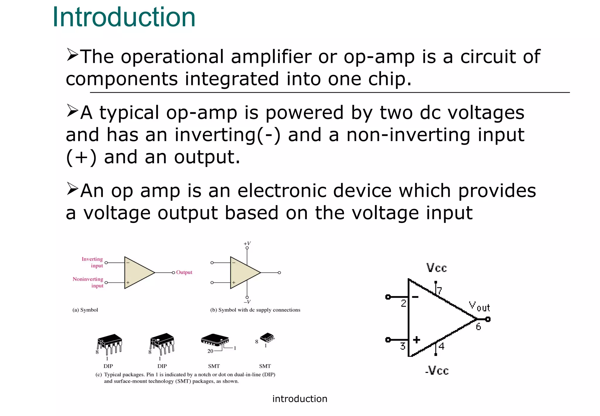
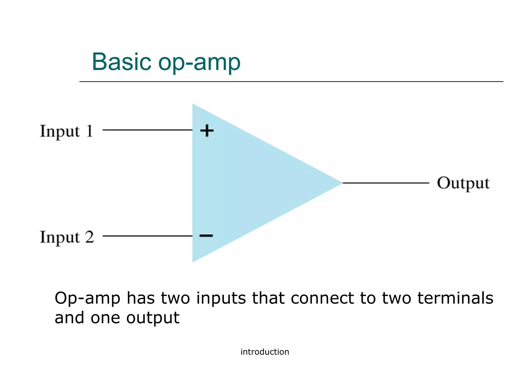
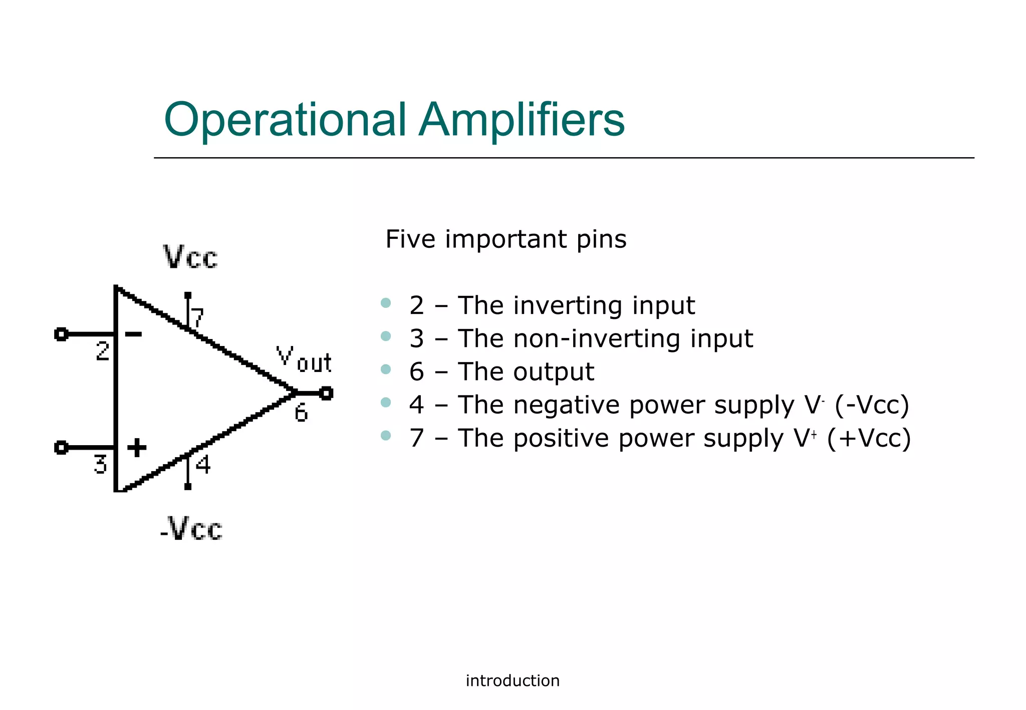
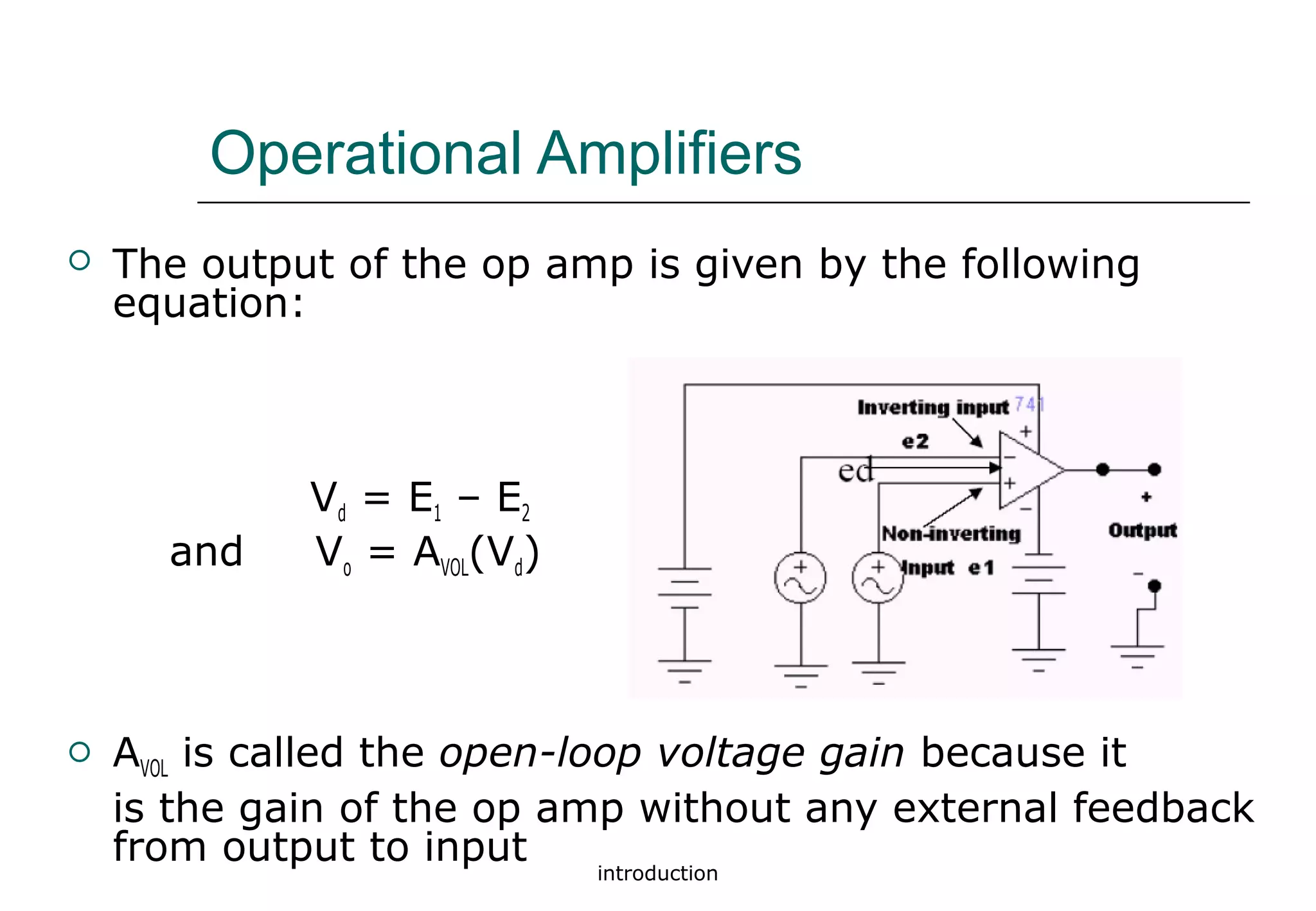
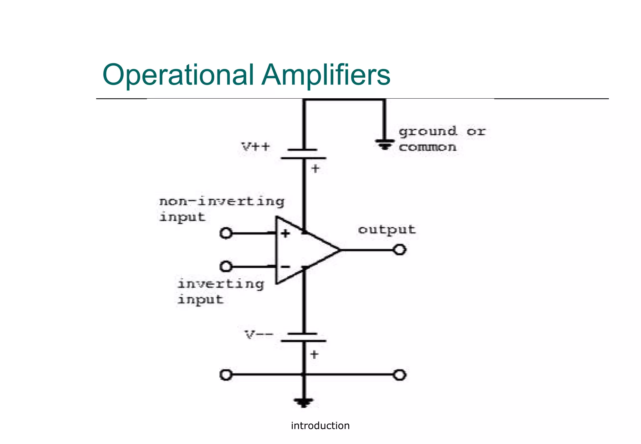
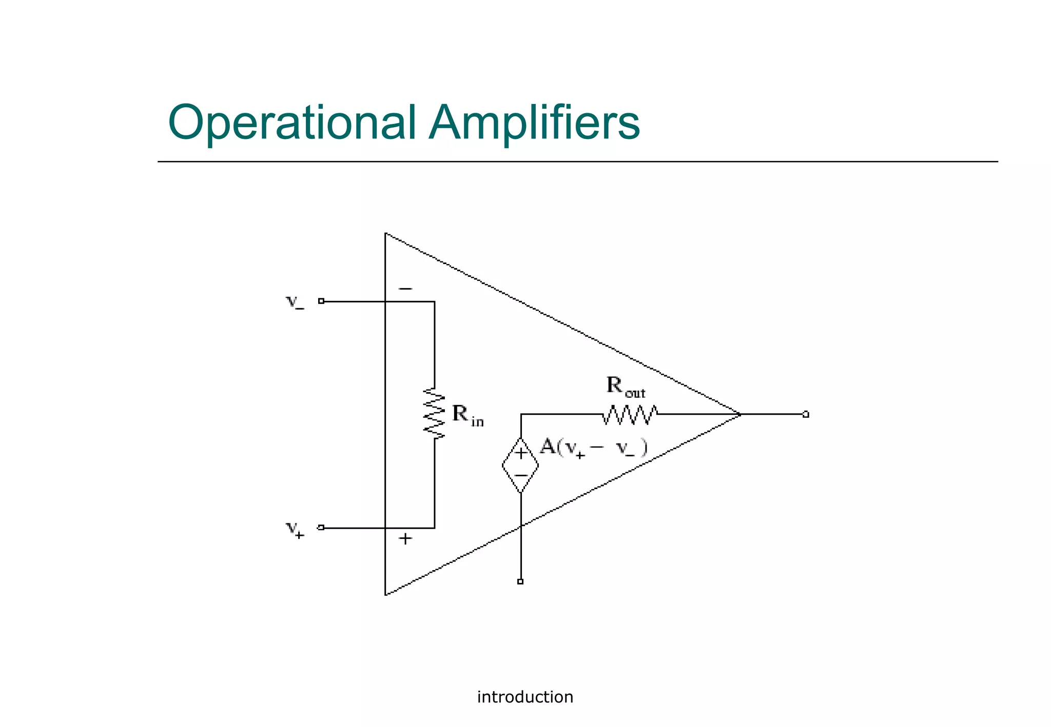
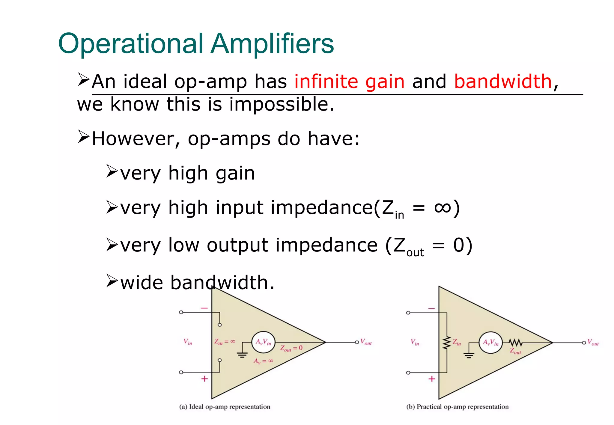
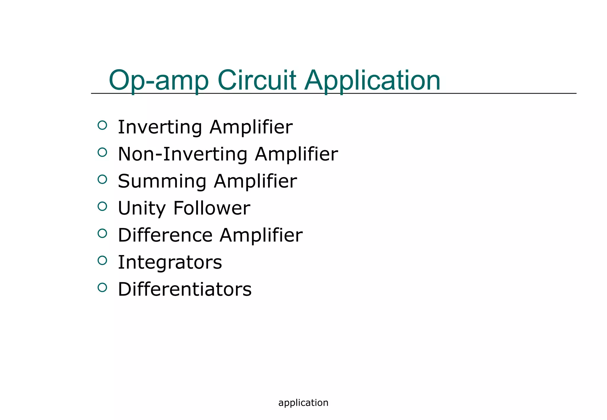
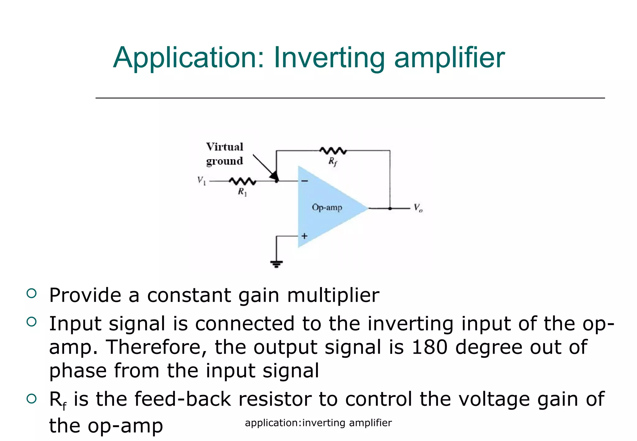
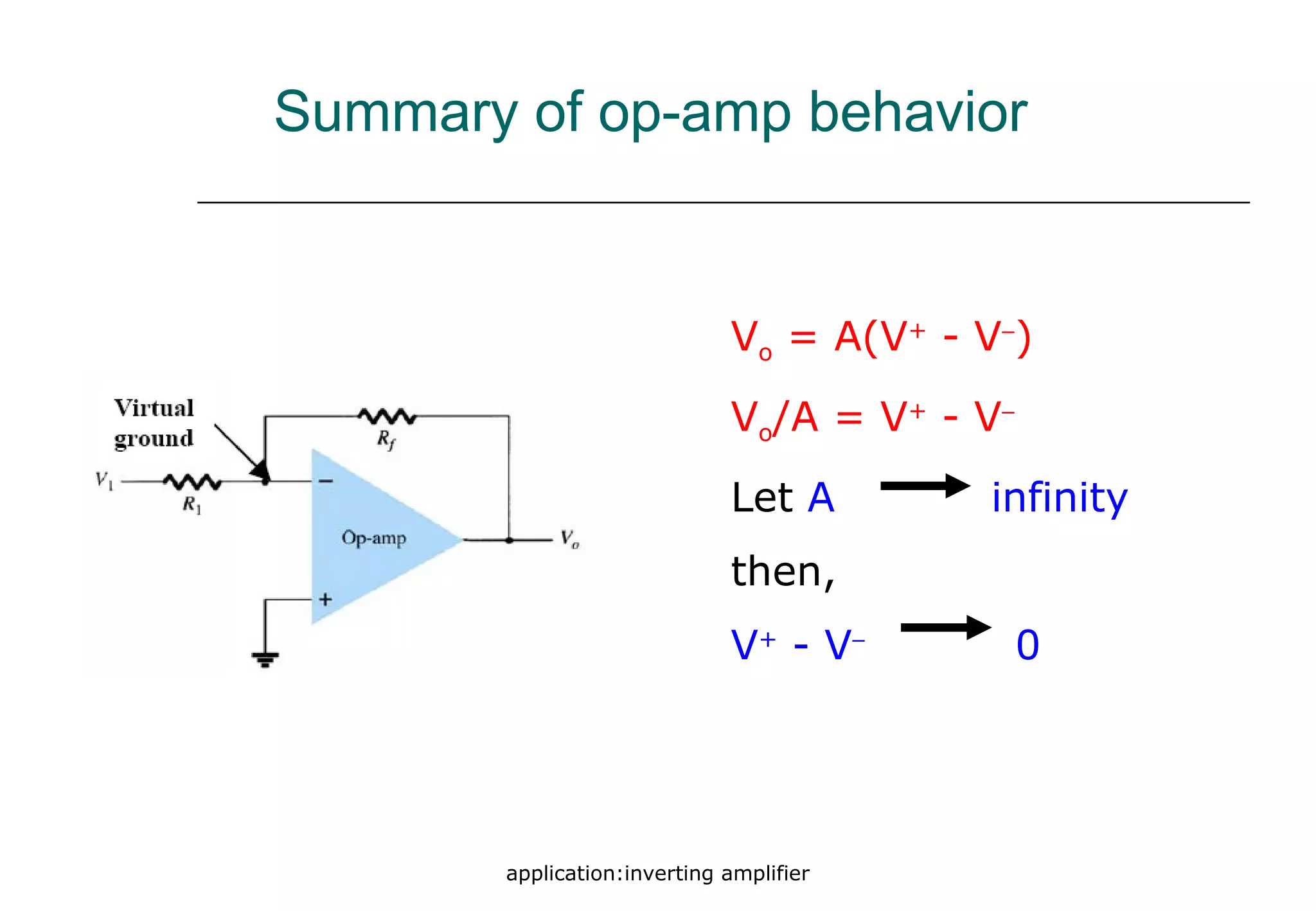
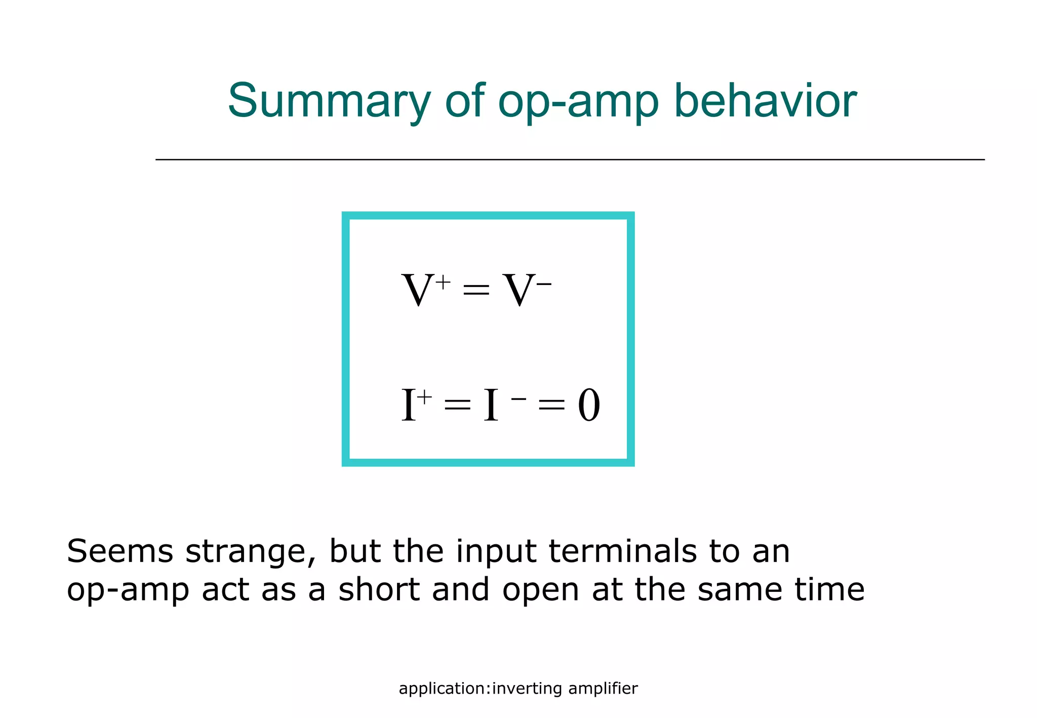
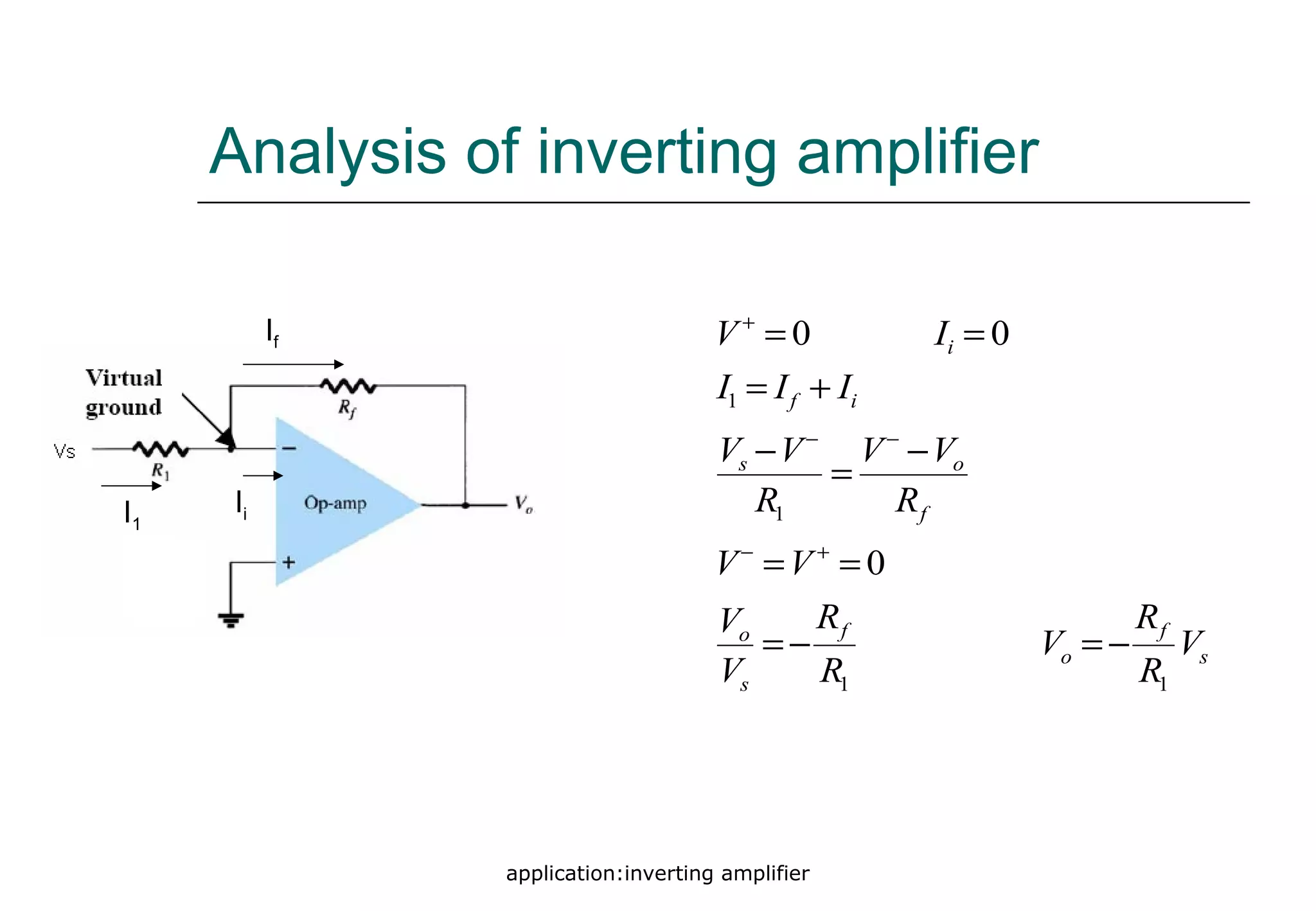
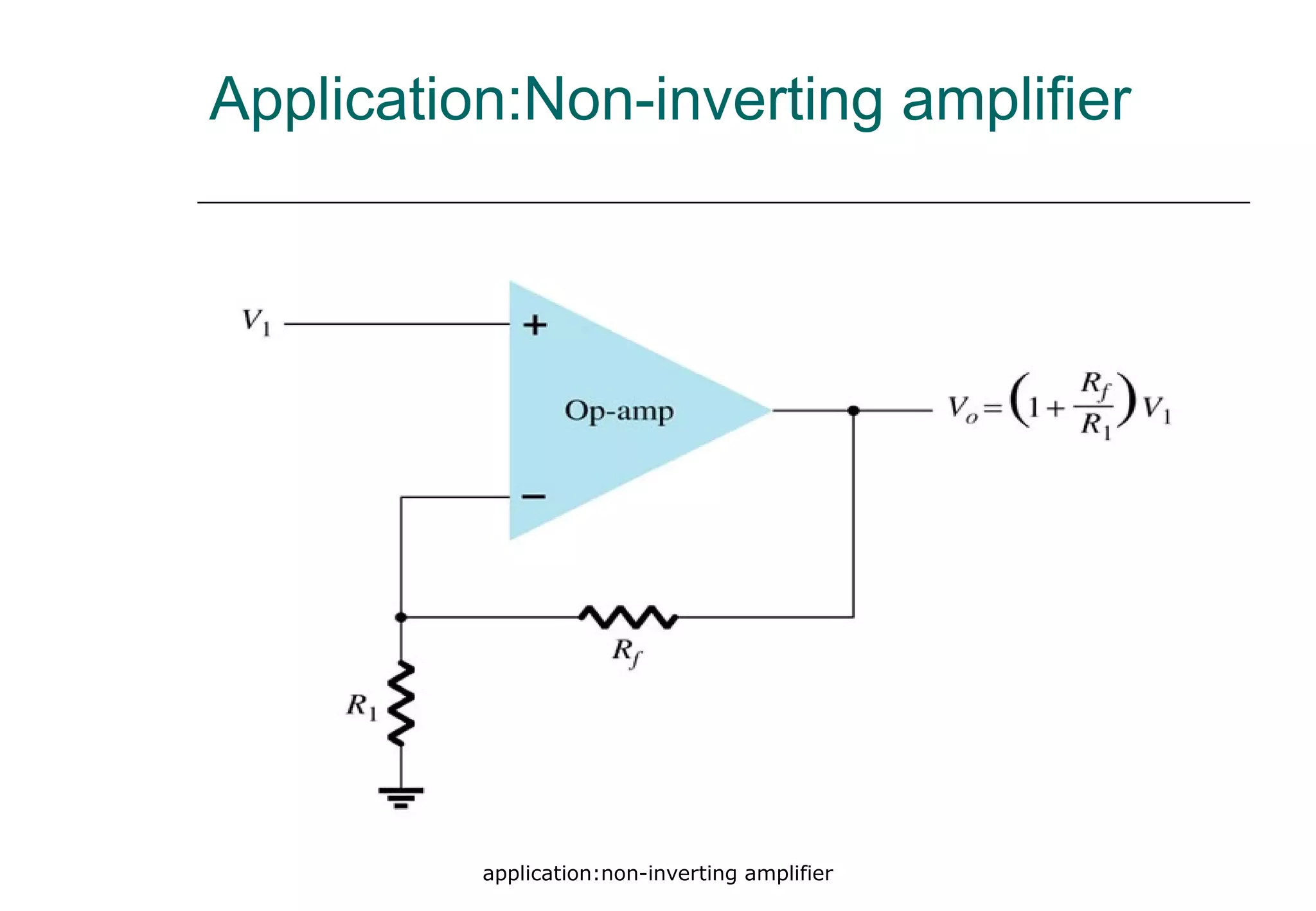
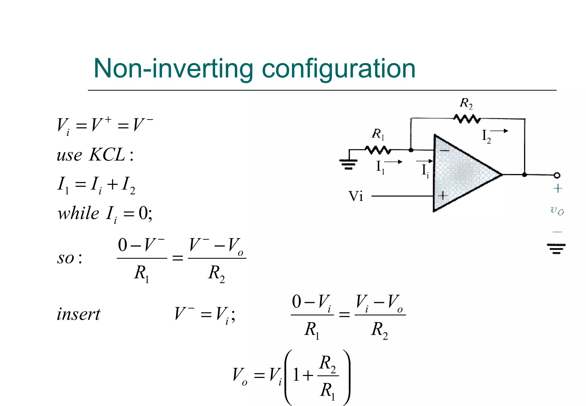
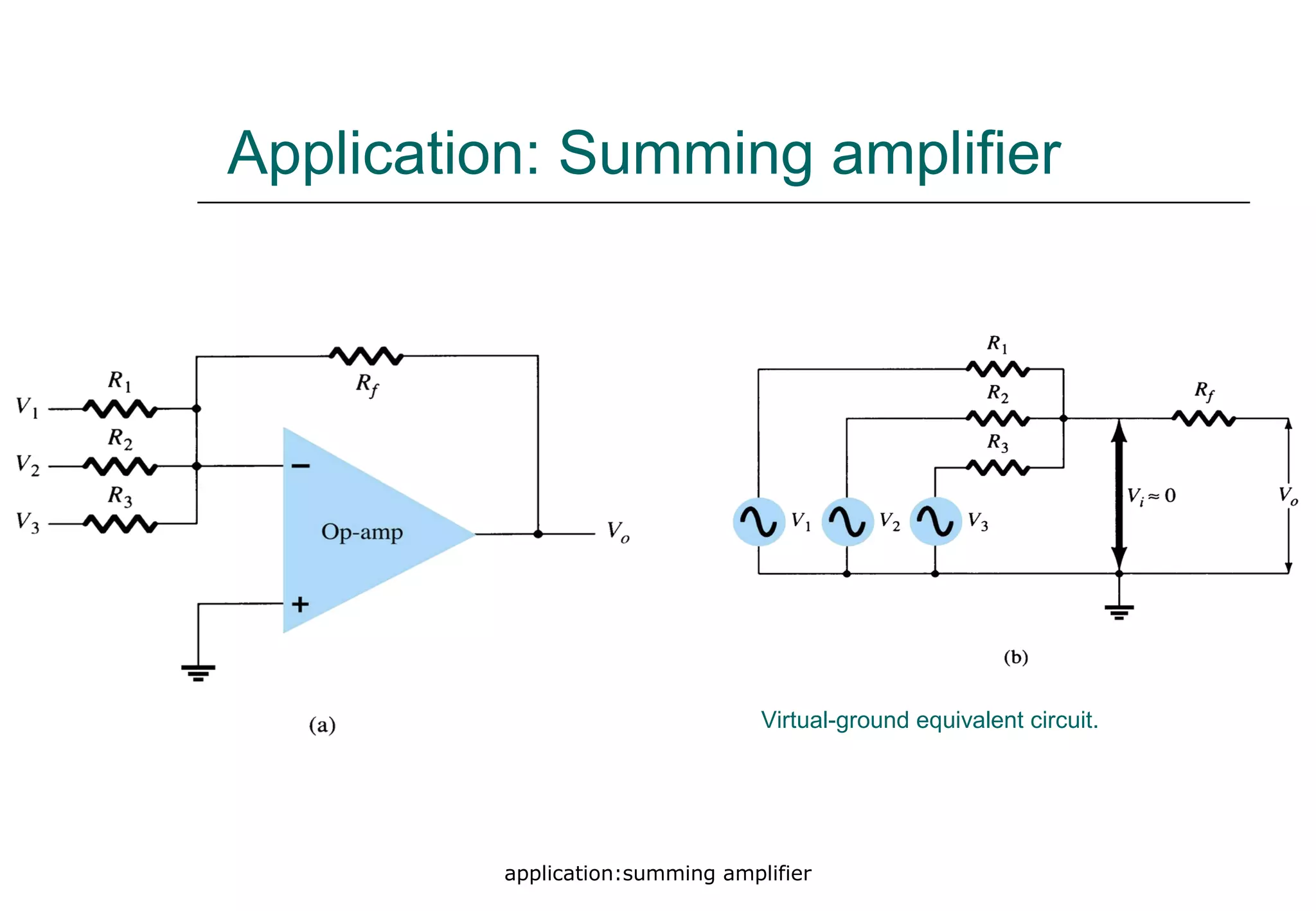
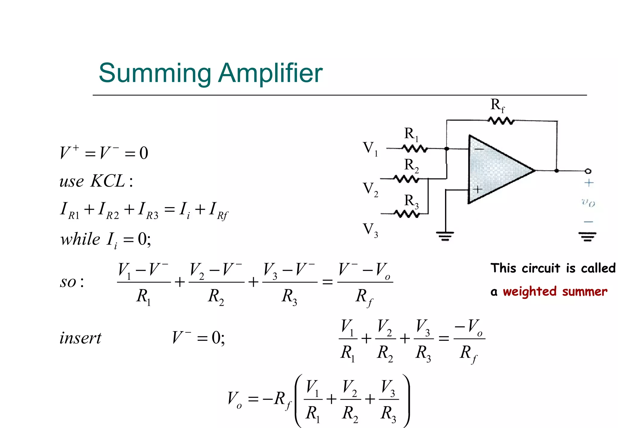
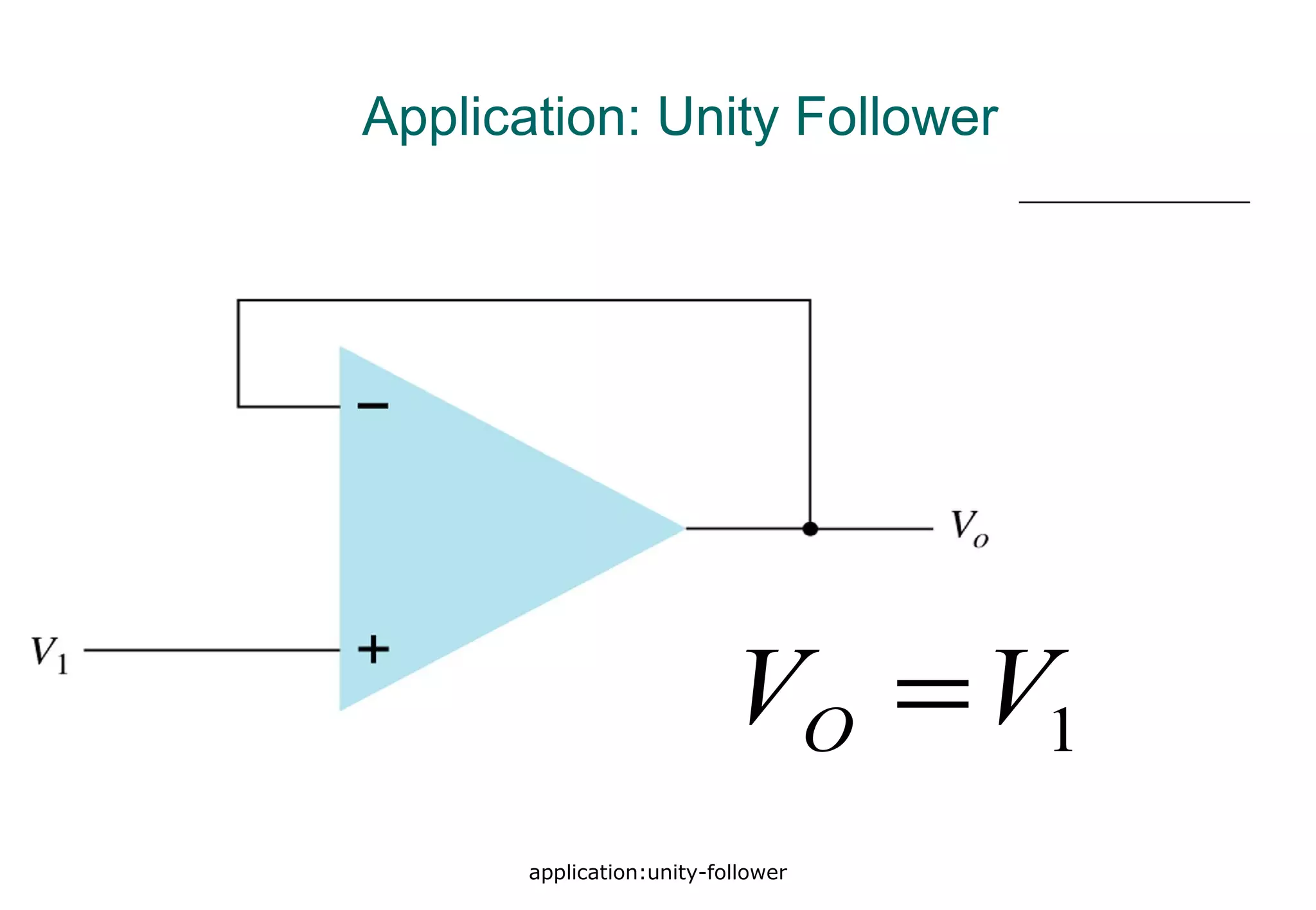
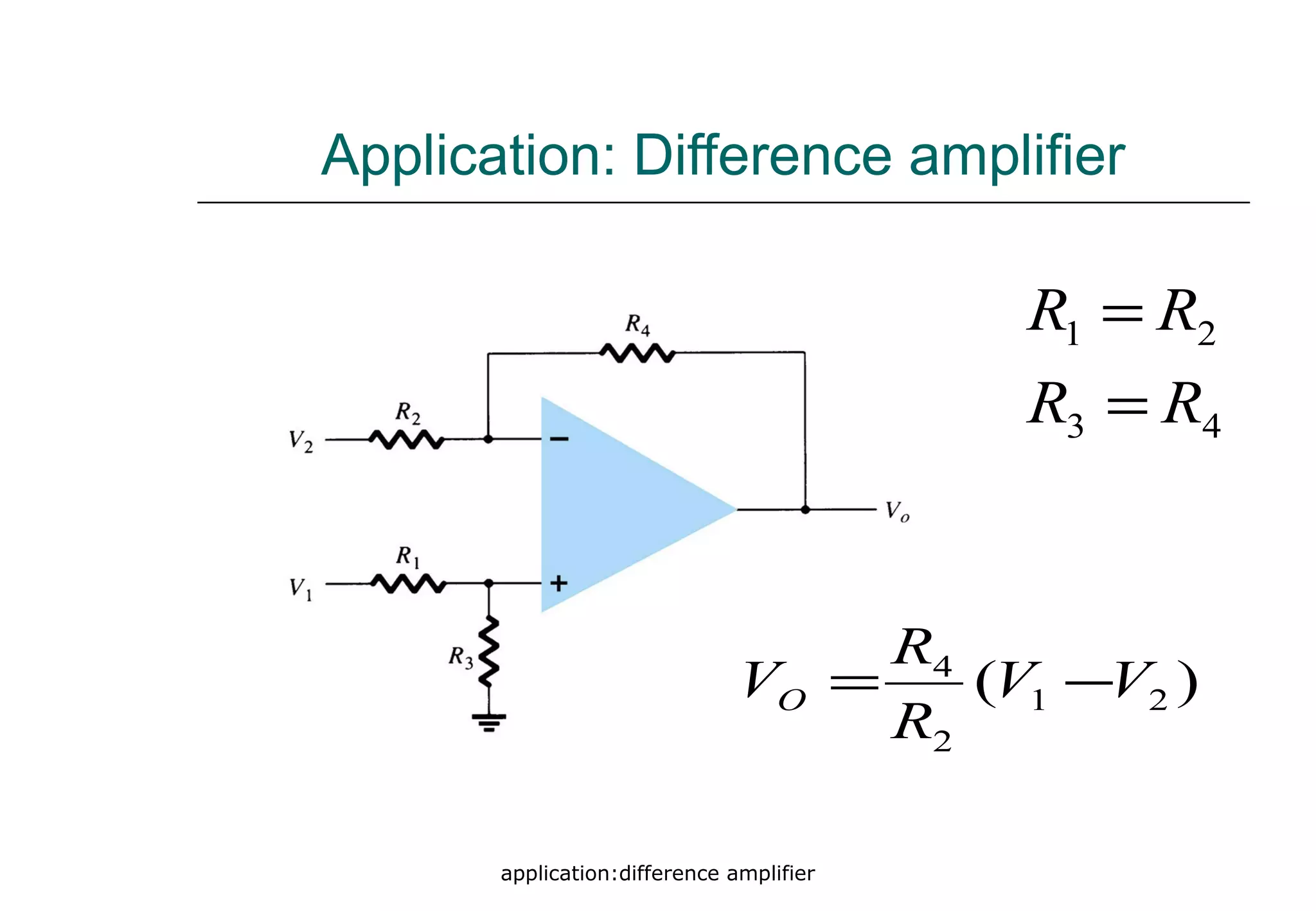
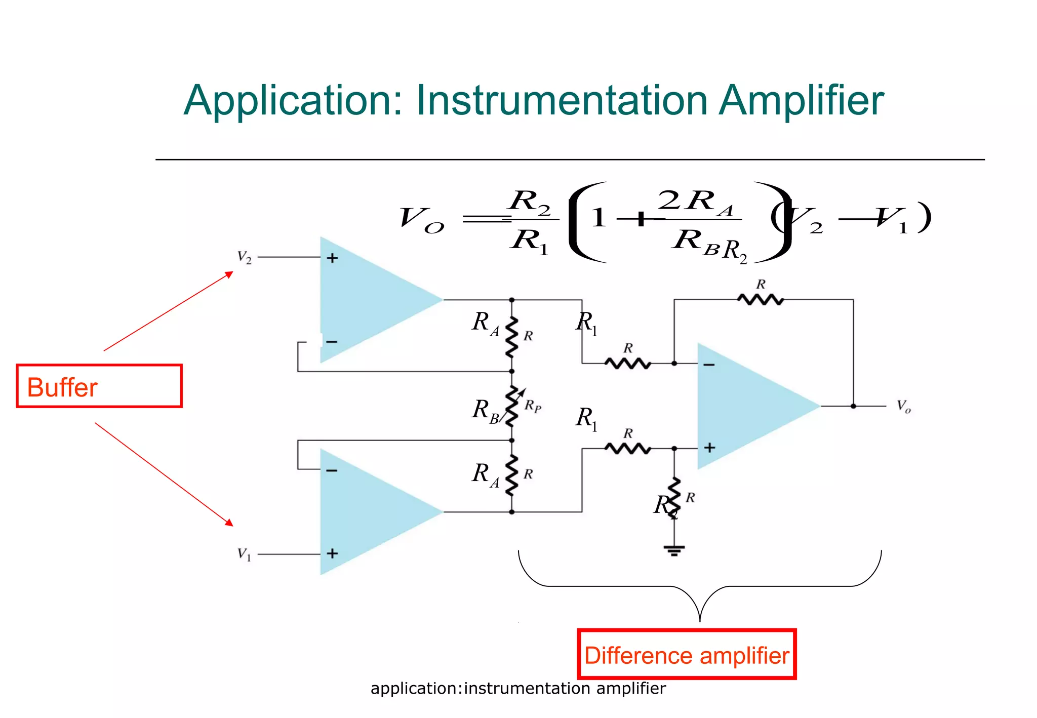
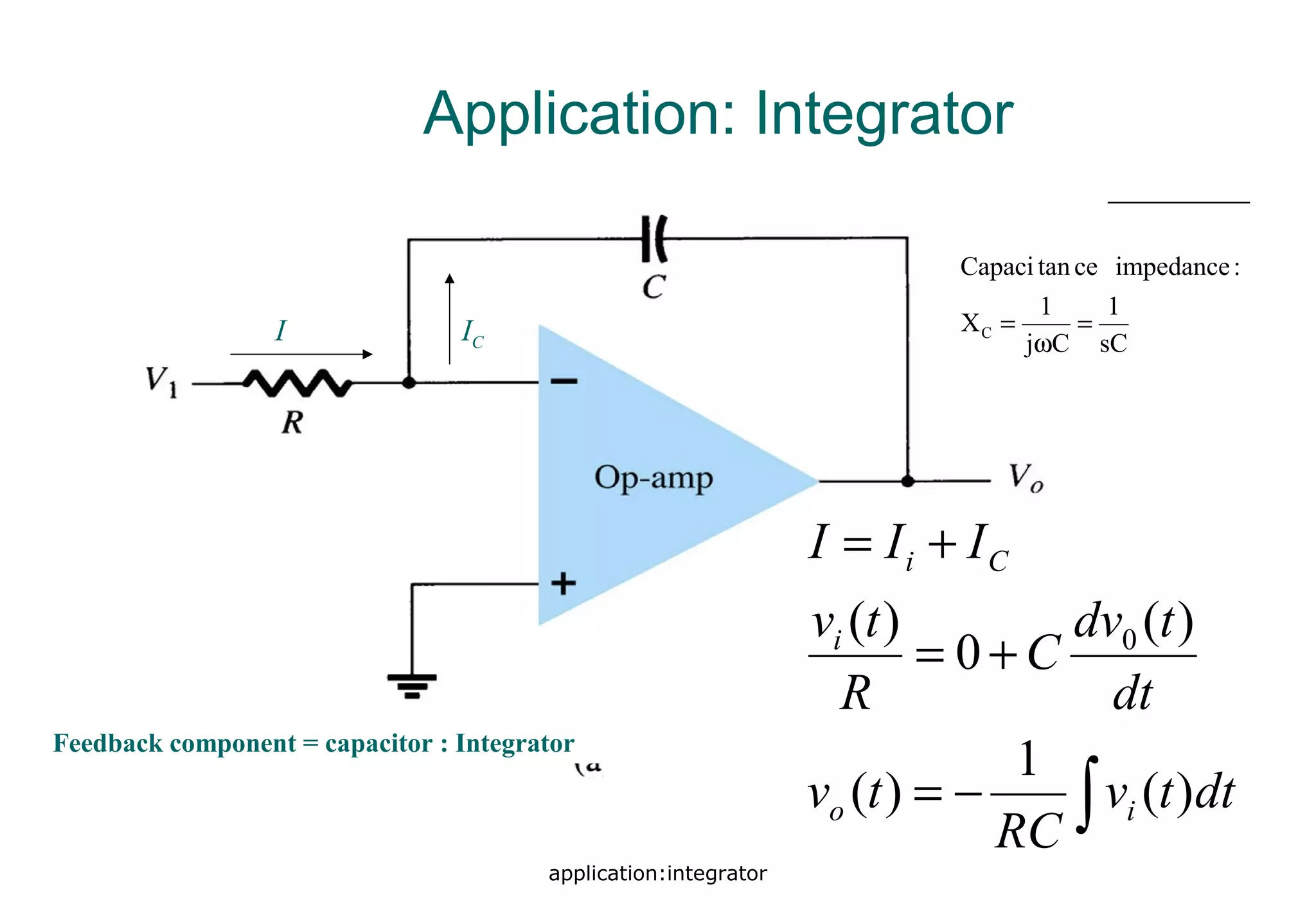
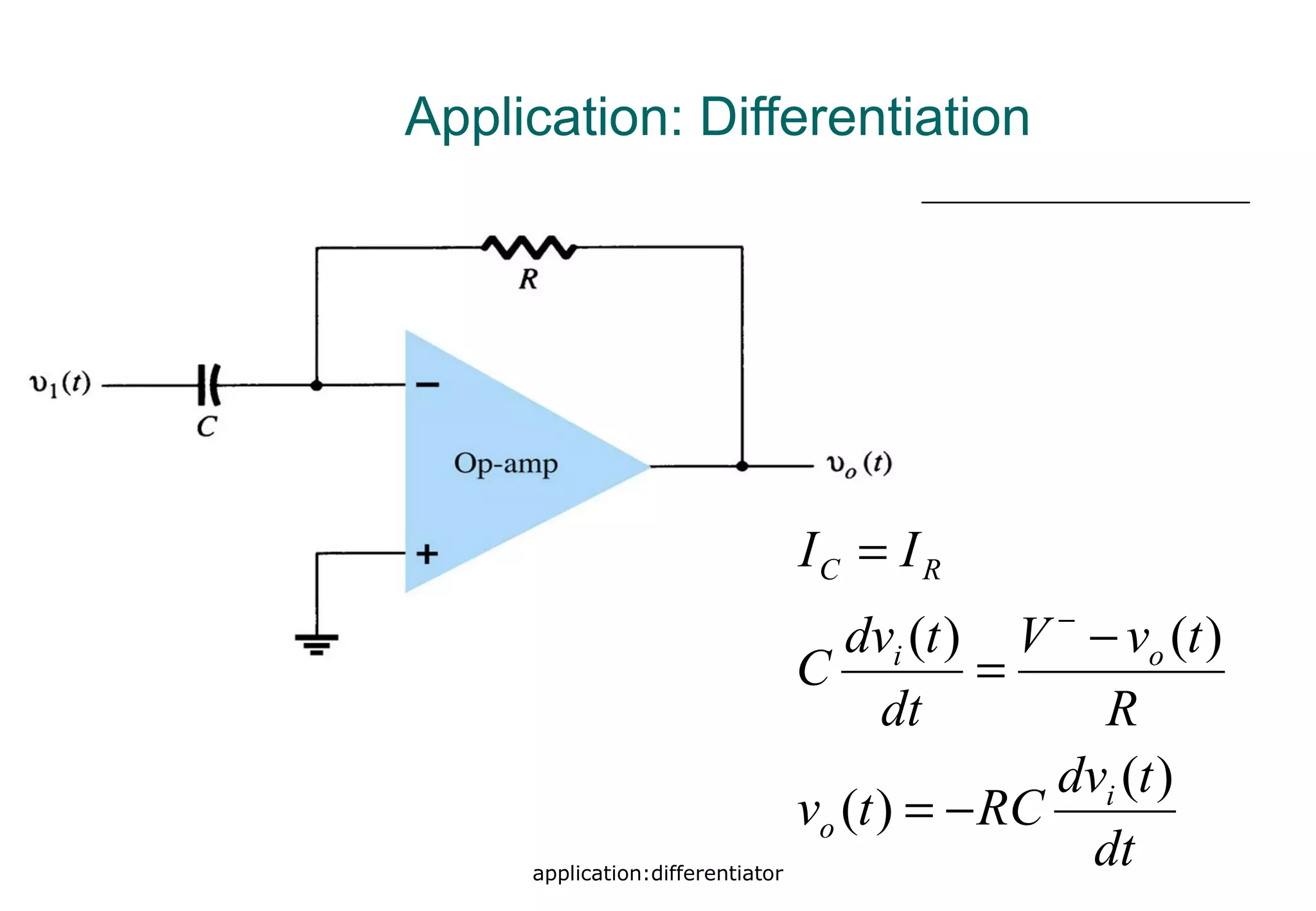
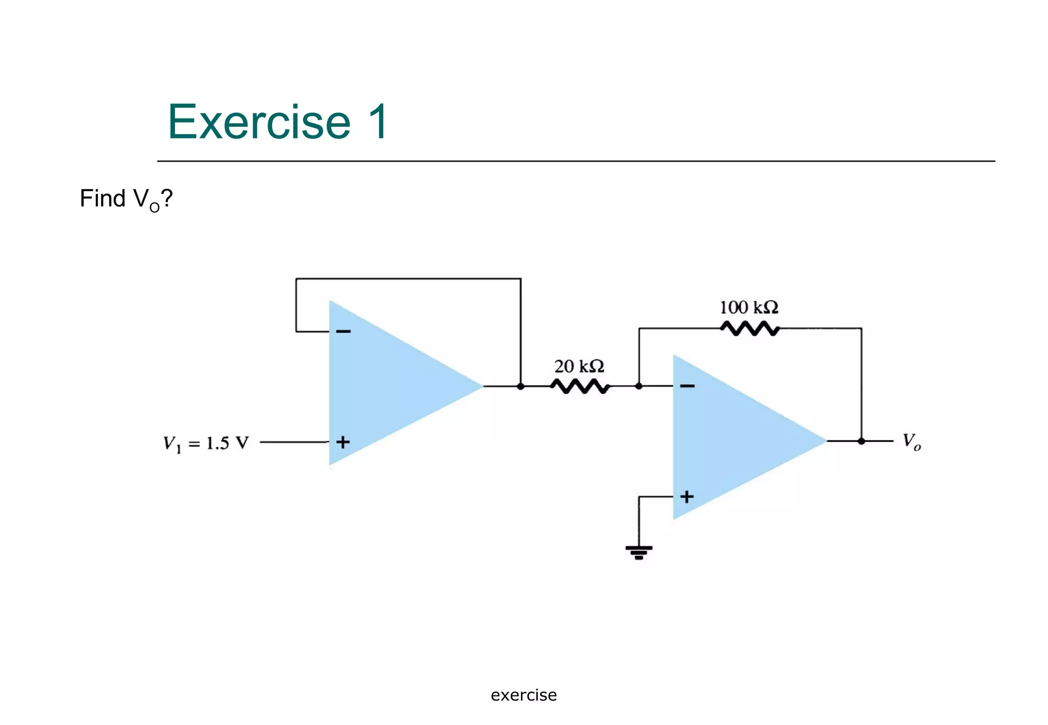
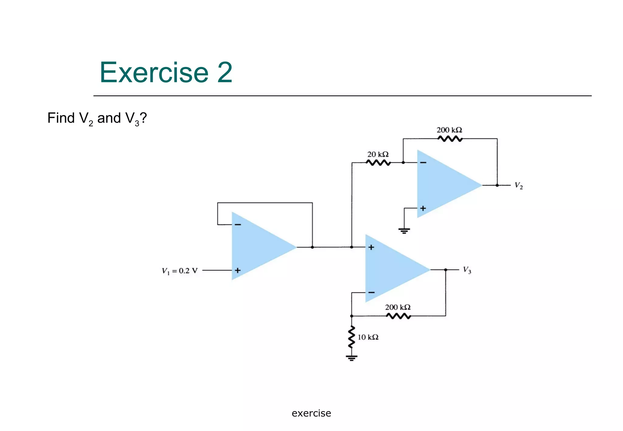
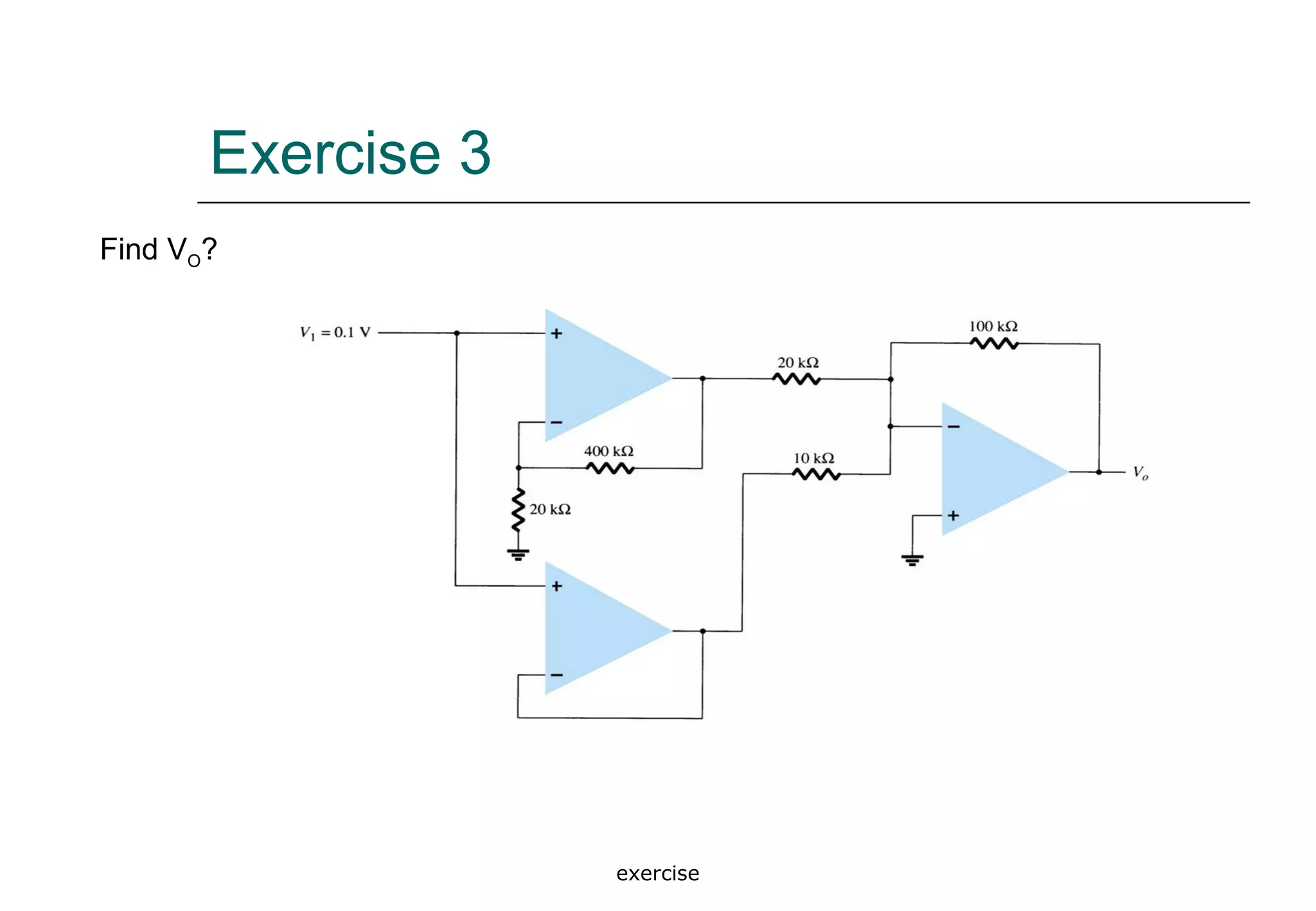
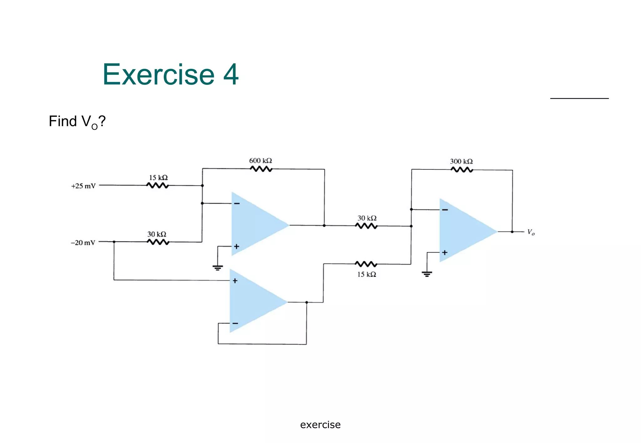
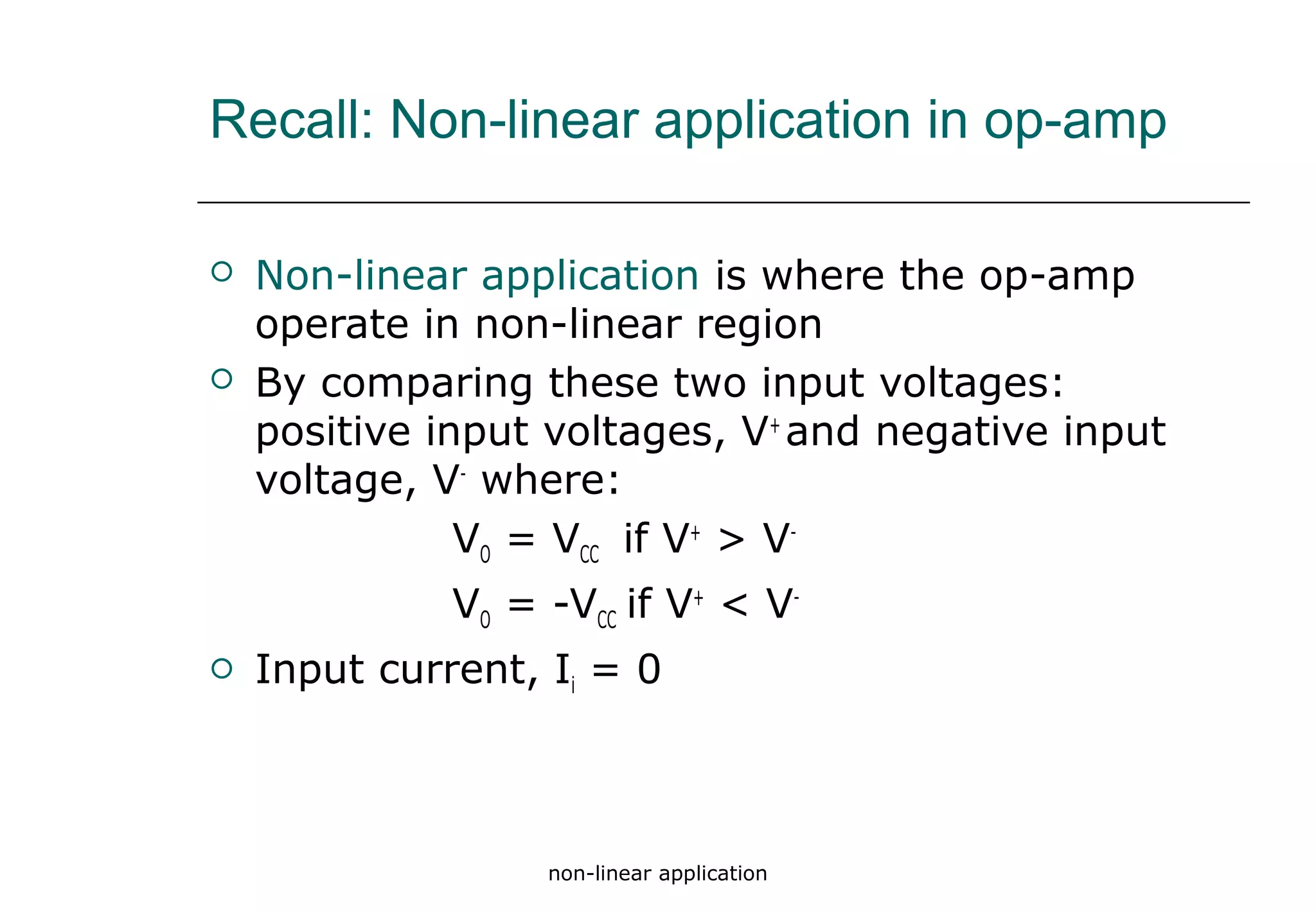
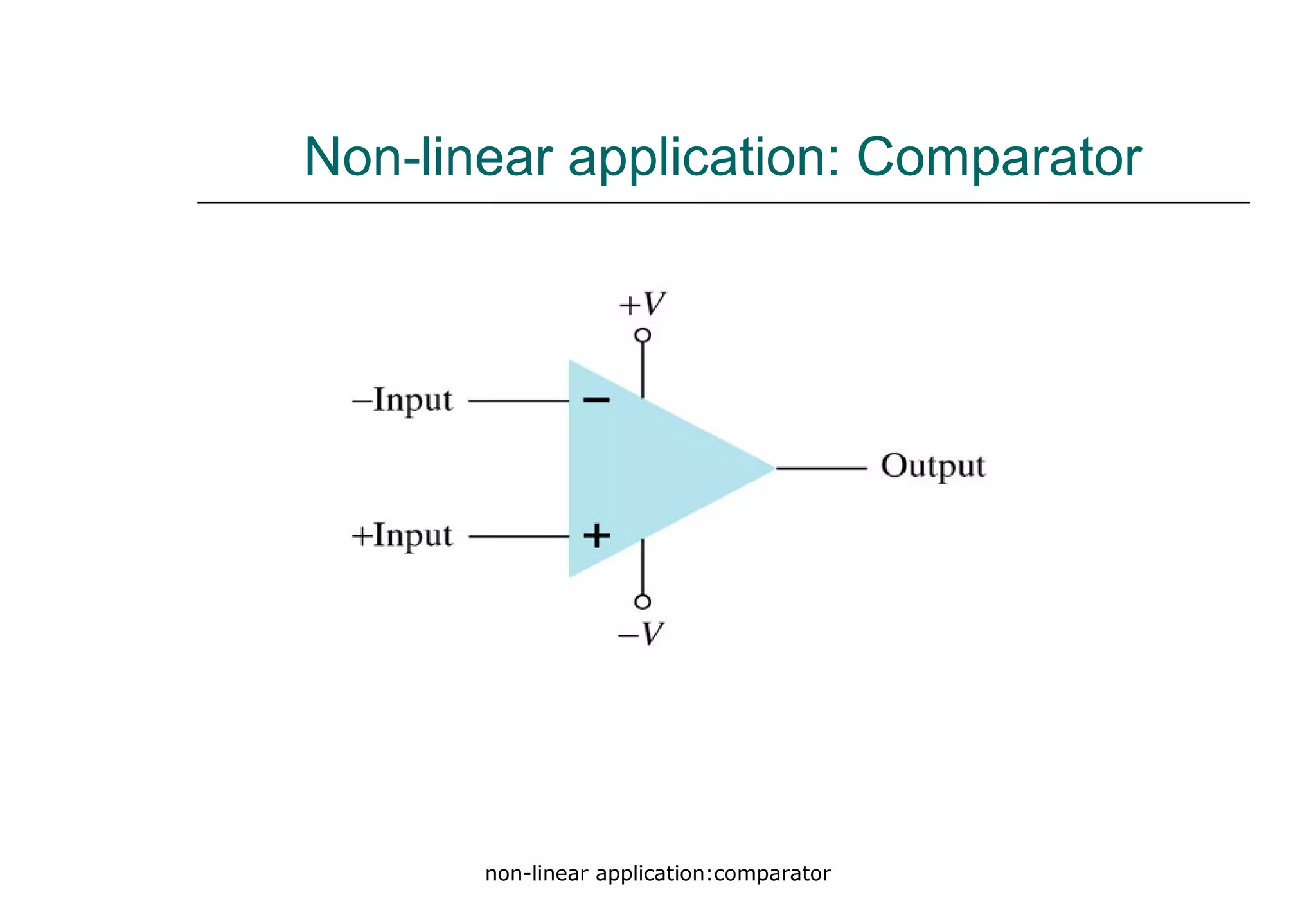

Operational amplifiers (op-amps) are integrated circuits with two inputs and one output that amplify voltage based on the difference between input signals. They can be used in various applications such as linear and non-linear operations, with configurations including inverting, non-inverting, summing, and difference amplifiers. Ideal op-amps have infinite gain and bandwidth, though practical versions exhibit high gain, high input impedance, and low output impedance.


