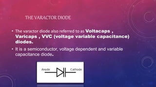
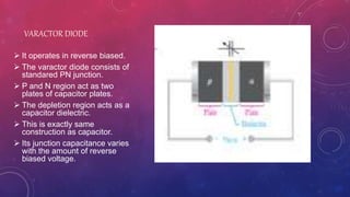
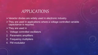
VARACTOR DIODE
THE VARACTOR DIODE
• The varactor diode also referred to as Voltacaps ,
Varicaps , VVC (voltage variable capacitance)
diodes.
• It is a semiconductor, voltage dependent and variable
capacitance diode.
 It operates in reverse biased.
 The varactor diode consists of
standared PN junction.
 P and N region act as two
plates of capacitor plates.
 The depletion region acts as a
capacitor dielectric.
 This is exactly same
construction as capacitor.
 Its junction capacitance varies
with the amount of reverse
biased voltage.
VARACTOR DIODE
BASIC OPERATION
∁ = 𝜀𝐴
𝑑
 A is plate area ,d is plate
separation and 𝜀 is the
dielectric constant.
 d∝ √v C∝
1
𝑑
 C∝
1
√𝑣
 Capacitance parameters are
controlled by
1. Doping.
2. Size and geometry of
diode construction.
GRAPHICAL ANALYSIS
In this graph the reverse biased voltage ranges from
(1-30v).
Capacitance ranges from 30pf to slightly less then 4pf
 As V become higher the decrease in capacitance
become smaller.
APPLICATIONS
Varactor diodes are widely used in electronic industry.
They are used in applications where a voltage controlled variable
capacitance is required.
They are used in
1. Voltage controlled oscillators
2. Parametric amplifiers
3. Frequency multipliers
4. FM modulator

Varactor Diode

  • 1.
  • 2.
    THE VARACTOR DIODE •The varactor diode also referred to as Voltacaps , Varicaps , VVC (voltage variable capacitance) diodes. • It is a semiconductor, voltage dependent and variable capacitance diode.
  • 3.
     It operatesin reverse biased.  The varactor diode consists of standared PN junction.  P and N region act as two plates of capacitor plates.  The depletion region acts as a capacitor dielectric.  This is exactly same construction as capacitor.  Its junction capacitance varies with the amount of reverse biased voltage. VARACTOR DIODE
  • 4.
    BASIC OPERATION ∁ =𝜀𝐴 𝑑  A is plate area ,d is plate separation and 𝜀 is the dielectric constant.  d∝ √v C∝ 1 𝑑  C∝ 1 √𝑣  Capacitance parameters are controlled by 1. Doping. 2. Size and geometry of diode construction.
  • 5.
    GRAPHICAL ANALYSIS In thisgraph the reverse biased voltage ranges from (1-30v). Capacitance ranges from 30pf to slightly less then 4pf  As V become higher the decrease in capacitance become smaller.
  • 7.
    APPLICATIONS Varactor diodes arewidely used in electronic industry. They are used in applications where a voltage controlled variable capacitance is required. They are used in 1. Voltage controlled oscillators 2. Parametric amplifiers 3. Frequency multipliers 4. FM modulator