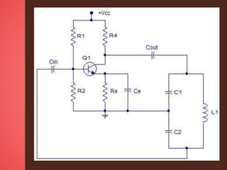
Electronic Oscillator ,classification ,linear and non linear ,circuit description , tank circuit ,working and operation , frequency of oscllation and Applications
Colpitts Oscillator - Working and Applicationselprocus
We provide you Project Colpitts Oscillator - Working and Applications.You can choose the best of your choice and interest from the list of topics we suggested. All new project ideas that are appearing focuses to improve the knowledge of Engineering students.
https://www.elprocus.com
Visit our page to get more ideas on Project Report Format for Final Year Engineering Students these ideas developed by professionals.
Elprocus provides free verified electronic projects kits around the world with abstracts, circuit diagrams, and free electronic software. We provide guidance manual for Do It Yourself Kits (DIY) with the modules at best price along with free shipping.
RC oscillators are a type of feedback oscillator; they consist of an amplifying device, a transistor, vacuum tube, or op-amp, with some of its output energy fed back into its input through a network of resistors and capacitors, an RC network, to achieve positive feedback, causing it to generate an oscillating
1. A multivibrator can implement simple two-state systems like oscillators, timers, and flip-flops. There are three types: astable which oscillates between states, monostable which is stable in one state until triggered to the other, and bistable which remains in either state.
2. An astable multivibrator consists of two amplifying devices cross-coupled by resistors and capacitors that cause it to continuously oscillate between two states.
3. A monostable multivibrator is stable in one state until an external trigger briefly changes its state, after which it returns to the original stable state for a set time period, functioning as a timer.
Digital Electronics (EC8392) UNIT-II -PPT-S.SESHA VIDHYA/ ASP/ECESeshaVidhyaS
The document discusses the design of various combinational logic circuits including multiplexers. It begins by defining combinational circuits as those whose outputs depend only on the current inputs and not prior inputs. Half adders, full adders, half subtractors, and full subtractors are designed using truth tables and Karnaugh maps. Larger multiplexers can be implemented using smaller multiplexers, such as an 8x1 multiplexer using two 4x1 multiplexers. Boolean functions can also be implemented using multiplexers by treating the minterms as inputs.
Comparator circuits compare two input voltages and produce a logic output signal that is high or low depending on which input is larger. Real comparators do not have an abrupt transition and have very high voltage gain in the transition region. Comparators are often used as interfaces between analog and digital circuits by converting analog signals to logic levels. Open-collector outputs are useful for this by producing either 0V or the supply voltage at their outputs. Schmitt triggers, which are comparators with positive feedback, are commonly used as they introduce hysteresis which helps eliminate unwanted output transitions from noise.
This document provides an overview of amplitude (linear) modulation techniques. It defines key concepts like modulation, baseband communication, and carrier communication. It then describes various amplitude modulation schemes including AM, DSB-SC, QAM, SSB, and VSB. Implementation and demodulation of these techniques is discussed. The document also covers frequency mixing, superheterodyne receivers, frequency division multiplexing, and carrier acquisition using phase-locked loops. Suggested problems are provided at the end.
This document discusses different types of voltage regulators. It describes linear regulators as either series or shunt types, with series regulators having a control element in series with the load and shunt regulators having a control element parallel to the load. Switching regulators are introduced as another type that passes voltage to the load in pulses to improve efficiency. Integrated circuit voltage regulators are also covered, including fixed positive and negative voltage regulators, as well as adjustable voltage regulators.
The document discusses DC and AC analysis of transistor amplifiers. It covers DC biasing circuits, voltage divider bias, graphical DC analysis using load lines and Q-point, AC equivalent circuits, and determining amplifier compliance from the AC load line. Key points are:
- DC load line shows all combinations of collector current (IC) and collector-emitter voltage (VCE) for given values of voltage and resistors.
- Q-point is the operating point where the load line intersects the transistor characteristic curve with no input signal.
- AC load line determines maximum output voltage compliance or swing based on saturation and cutoff points.
This document discusses digital to analog converters (DACs). It explains that a DAC converts digital numbers into analog voltages or currents. The key components of a DAC are its digital input, analog output, and conversion process. Common DAC types include binary weighted resistor DACs and R-2R ladder DACs, which use resistors and switches to implement the conversion. Important DAC specifications are also outlined such as reference voltage, resolution, speed, settling time, and linearity. Common applications of DACs include function generators, digital oscilloscopes, and converting digital video signals to analog formats for display.
This document discusses MOSFETs and JFETs. It introduces MOSFETs, describing the metal oxide layer and how the electric field controls current. It describes types of MOSFETs and their applications, particularly as switches. Characteristic curves of MOSFETs are also mentioned. The document then introduces JFETs, describing their structure and operation. Applications of JFETs as switches are provided. Advantages and disadvantages of JFETs are listed. Finally, characteristics curves of JFETs, including output and transfer characteristics, are described.
Testing and trouble shooting of multivibratorsSandeep Jamdar
The document provides information about various topics related to active testing of electronic circuits including voltage analysis, resistance analysis, and signal analysis. It describes how to perform voltage testing using a DMM, resistance testing using a multimeter to check continuity and component status, and signal analysis using an oscilloscope to observe waveforms. Troubleshooting procedures are provided for monostable multivibrators, phase shift oscillators, and clipping and clamping circuits. Transistor testing methods using a multimeter are also detailed.
Overview of Crystal Oscillator Circuit Working and Its Applicationelprocus
The document discusses crystal oscillator circuits, which use a piezoelectric crystal to create an electrical signal at a precise frequency. It describes different types of oscillator circuits, how quartz crystals produce oscillations via the piezoelectric effect, and example crystal oscillator circuit diagrams. Applications are discussed, including in microprocessors to provide clock signals, and industrial uses like computers, telecommunications equipment, and sensors.
This document discusses programmable logic devices (PLDs). It describes the different types of PLDs including SPLDs, CPLDs, and FPGAs. SPLDs are the least complex, while CPLDs have higher capacity than SPLDs and allow for more complex logic circuits. FPGAs have the greatest logic capacity and consist of an array of configurable logic blocks and programmable interconnects. The document also covers how PLDs are programmed using schematic entry or text-based entry along with required programming software and hardware.
Mini Project 2 - Frequency Shift Keying (FSK) Modulator and DemodulatorAIMST University
This document outlines a laboratory project on frequency shift keying (FSK) modulation and demodulation. The objectives are to generate an FSK modulated signal using a modulator circuit with a 555 timer IC and transmit binary data, and to demodulate the FSK signal using a demodulator circuit with a 565 phase locked loop. Students will construct the circuits according to the specifications, test them, and write a report explaining FSK theory and operations, describing the printed circuit board fabrication and assembly, and presenting the results.
This document discusses latches and flip-flops. It describes the SR latch, gated SR latch, D latch, and gated D latch. It also covers edge-triggered flip-flops including the SR, D, and JK flip-flops. The key uses of flip-flops are for data storage, data transfer, counting, and frequency division in digital circuits and sequential logic.
This document discusses the design philosophy of integrated circuits and biasing techniques. It begins with an overview of constraints in IC design such as minimizing resistors and replacing them with transistors. It then discusses current sources, current mirrors, and current steering circuits which are used to generate constant currents for biasing multiple amplifier stages. The document compares MOSFET and BJT transistors. It explains that current sources use a transistor connected as a diode to generate a constant current, and current mirrors replicate this current. Current steering circuits distribute current from current sources to multiple locations. The document concludes with a brief section on the high frequency response of IC amplifiers.
This document summarizes a student's presentation on crystal oscillators. It begins with an introduction explaining that a crystal oscillator uses a piezoelectric crystal to create a precise electrical signal. It then discusses the crystal structure and materials used, primarily quartz, as well as the basic harmonic oscillator structure and equivalent circuit of a crystal oscillator. Applications mentioned include use in electronics for timekeeping, communications, and industrial/consumer devices.
The main objective of this project is controlling speed of BLDC motors with the help of microcontroller. To make the industry automation the equipment and machineries should be controlled automatically. So control of the machineries which involving this motor can be done accurately. It displays its speed using an IR method of speed sensor mechanism.
The document discusses CMOS technology which uses both NMOS and PMOS transistors in a complementary way. It has low power dissipation as power is only consumed during switching. CMOS circuits like inverters, NAND and NOR gates are constructed using a pull-up network of PMOS transistors and a pull-down network of NMOS transistors. The fabrication of CMOS transistors involves depositing and patterning materials on a silicon wafer through lithography. CMOS has advantages like low power, high noise immunity and is widely used in applications like computers, processors and memory chips.
This document is a presentation on emitter-coupled logic (ECL) given to a lecturer. It discusses the basics of ECL, including its differential amplifier configuration, lower time delay compared to other logic gates, use of negative voltage supply, and why it provides faster switching. It also covers some disadvantages of ECL like low fan-out and input-output voltage variations not matching. The presentation explains the basic circuit diagram and operation of ECL, showing how voltages are more negative for logic low and less negative for logic high. It further discusses how ECL provides faster speed due to a small voltage swing of 75mV when the emitter current is 95% or 5% of its operating current. The presentation addresses how
As we have discussed that out of various triggering methods to turn the SCR, gate triggering is the most efficient and reliable method. Most of the control applications use this type of triggering because the desired instant of SCR turning is possible with gate triggering method.
A simple N-channel MOSFET can be used as a diode, Switch and Active resistor. This presentation is a part of course of Analog CMOS Design, based on textbook of same title by Allen Holberg.
Part of Lecture series on EE321N, Power Electronics-I delivered by me during Fifth Semester of B.Tech. Electrical Engg., 2012
Z H College of Engg. & Technology, Aligarh Muslim University, Aligarh
Please comment and feel free to ask anything related. Thanks!
TTL is a logic family consisting of bipolar junction transistors and resistors. It was developed in 1961 and commercially used in 1963. There are several sub-families of TTL that differ in speed and power characteristics, including standard TTL, low power TTL, and high-speed TTL. TTL uses 5V power and 0V/0.2V logic levels, has a fan-out of 10 and propagation delay of around 9ns. It is used in applications like processors, printers, and displays. TTL gates come in open collector, totem pole, and three-state configurations to provide different output characteristics.
The document discusses the structure and operation of MOS transistors. It describes the basic MOS structure which consists of a metal gate separated from a semiconductor substrate by an oxide layer. Applying a voltage to the gate can induce an inversion layer in the semiconductor to form a channel between the source and drain, allowing current to flow. The threshold voltage is the minimum gate voltage required to form an inversion layer. The document discusses n-channel MOSFETs and their characteristics in different regions of operation defined by the gate-source voltage.
This document discusses interfacing a digital-to-analog converter (DAC) with an 8051 microcontroller. It explains that a DAC is used to convert digital pulses from the 8051 into analog signals that can be read by systems requiring analog inputs. Specifically, it describes using an 8-bit DAC 0808 chip to convert digital data from the 8051 into a corresponding analog output voltage. It also provides 8051 assembly code examples to generate triangular and square wave outputs using a DAC interfaced with an 8051 port.
The document describes a multistage transistor amplifier. It defines a multistage amplifier as having multiple amplifier stages connected in series using coupling devices. It discusses different types of coupling devices like RC, RL, LC and transformer coupling. It explains the working of a typical multistage amplifier including how the gain is calculated as the product of individual stage gains. It describes how the frequency response varies with lower gains at very low and very high frequencies. Advantages include low cost and good frequency response. Disadvantages include increased noise over time and poor impedance matching. Multistage amplifiers are widely used as voltage amplifiers in audio applications.
The document describes the design of a 0-9 binary coded decimal (BCD) counter circuit. The circuit uses a 74LS90 BCD decade counter integrated circuit to count from 0 to 9, and a 74LS47 BCD to 7-segment decoder driver integrated circuit to display the count on a 7-segment display. When a push button is pressed, the counter increments and the display updates to show the new count. Potential applications mentioned include token counters, production line counting systems, clocks, and timers.
Oscillators convert DC to AC signals using a feedback loop that sustains oscillations. Common oscillator circuits include LC, RC, quartz, and relaxation oscillators. The Hartley oscillator uses a tapped coil and capacitor in a feedback loop to generate radio frequencies. The Colpitts oscillator also uses an LC tank circuit but with capacitors in the feedback path. The Franklin oscillator uses two transistors and an LC circuit, with each transistor inverting the phase to sustain oscillations. The Wein bridge oscillator is an RC circuit that produces sine waves with high quality resonance and tuning capabilities. Oscillators are used to generate signals for applications like radio transmission, testing equipment, and sensors.
This document describes different types of oscillators. It discusses oscillators that use positive feedback to generate AC signals at a desired frequency. It provides block diagrams and explanations of RC phase shift oscillators, Wein bridge oscillators, Hartley oscillators, Colpitts oscillators, and Clapp oscillators. Equations for calculating the oscillation frequency of each type of oscillator are also presented.
The document describes the Colpitts oscillator circuit. It consists of an LC tank circuit made of capacitors and an inductor that produces sustained oscillations. The capacitors provide positive feedback to sustain oscillations at the resonant frequency of the tank circuit. It works by the energy transferring between the capacitors and inductor in the tank circuit. The Colpitts oscillator can generate high frequency sinusoidal waves and is commonly used as a local oscillator in radio receivers [END SUMMARY]
Oscillator is a mechanical or electronic device works on the principle of oscillation i.e. a periodic fluctuation between two things based on changes in energy. It is of two types; linear oscillators and non linear oscillators. The wave shape and amplitude are determined by the design of the oscillator circuit and choice of component values.
Oscillator is a mechanical or electronic device works on the principle of oscillation i.e. a periodic fluctuation between two things based on changes in energy. It is of two types; linear or Harmonic oscillator and Relaxation or non linear oscillator.Oscillator is a mechanical or electronic device works on the principle of oscillation i.e. a periodic fluctuation between two things based on changes in energy.
An oscillator is an electronic circuit that produces repetitive waveforms without an external input signal. It converts DC power from a source into AC power in a load. There are two main types of oscillators - sinusoidal oscillators that produce sinusoidal waveforms and relaxation oscillators that produce non-sinusoidal waveforms like square or sawtooth waves. Crystal oscillators use a quartz crystal as the frequency-determining element, giving them extremely high frequency stability. They are commonly used where high accuracy is required, such as in communication systems, laboratory equipment, and computers.
This document provides an overview of different types of electronic oscillators. It begins with introducing oscillators and their basic components. It then describes several common oscillator circuits in more detail, including tuned collector oscillators, tuned base oscillators, Hartley oscillators, Colpitts oscillators, and Clapp oscillators. It discusses the working principles, construction, and frequency of oscillation calculations for some of these oscillator types. The document provides a useful reference for understanding the different categories of oscillators and how they generate oscillations.
An oscillator is an amplifier which produces an output signal of significant high power whose waveform is similar to the input signal. It is an electronic circuit which generates an ac output signal without requiring any external input signal.
The document discusses positive feedback amplifiers and oscillator circuits. It begins by defining oscillation and oscillators, and describes how oscillators are used to generate signals in communications, computing, and test equipment. It then classifies oscillators based on their waveforms, operating mechanisms, frequencies, and circuit types. The document explains the Barkhausen criteria that must be met for oscillations to start and be sustained. It provides examples of common oscillator circuits like Hartley, Colpitts, RC phase shift, Wien bridge, and crystal oscillators. It analyzes the operating principles, feedback networks, and conditions for oscillation of these oscillator types. The document emphasizes that crystal oscillators provide the most stable output frequencies.
The document discusses oscillators and their working principles. It begins by classifying oscillators and analyzing their circuits. It describes the conditions for oscillation using the Barkhausen criteria. It then examines tuned oscillators, crystal oscillators, and other oscillator types. Applications of oscillators in communication circuits, timers, and other devices are also overviewed.
The document discusses different types of oscillators:
1. Oscillators produce specific periodic waveforms like square, triangular, sawtooth, and sinusoidal waves using active and passive devices like resistors, capacitors, and inductors.
2. There are two main classes of oscillators: harmonic oscillators and relaxation oscillators.
3. A sinusoidal oscillator consists of an amplifier with part of its output fed back to the input in a feedback loop. The Barkhausen criterion must be satisfied for oscillations to occur.
The document discusses oscillators and feedback amplifiers. It defines positive and negative feedback, and describes their effects on gain. Oscillators generate an output signal without an external input through the use of positive feedback in an amplifier circuit. The two main types of oscillators are sinusoidal and non-sinusoidal oscillators. Common oscillator circuits discussed include the RC phase shift oscillator, Hartley oscillator, and common emitter amplifier configuration.
An oscillator is an electronic circuit that generates an alternating current signal through feedback and amplification. The oscillator contains a feedback path where part of the output signal is fed back to the input. For oscillation to be sustained, the feedback signal must be larger than and in phase with the input signal. Common waveforms produced by oscillators include sinusoidal and square waves. Oscillators are classified by the waveform type and frequency range. Sine wave oscillators use inductors and capacitors (LC oscillators) or crystals to control frequency, while relaxation oscillators produce square waves. Oscillators are essential components in electronic devices and are used as stable frequency sources in applications like timers, calculators, and oscilloscopes.
Study of vco_Voltage controlled OscillatorNeha Mannewar
Voltage controlled Oscillator,Voltage controlled oscillator is a type of oscillator where the frequency of the output oscillations can be varied by varying the amplitude of an input voltage signal.Voltage controlled oscillators are commonly used in frequency (FM), pulse (PM) modulators and phase locked loops (PLL). Another application of the voltage controlled oscillator is the variable frequency signal generator itself.
This presentation provides an overview of oscillators. It begins with an introduction and classification of oscillators. It then describes several common oscillator circuits including the tuned collector oscillator, Hartley oscillator, Colpitts oscillator, RC phase shift oscillator, and Wein bridge oscillator. Characteristics of each circuit like the feedback mechanism and frequency of oscillation are explained. Applications of oscillators in communication and electronics are mentioned. Key oscillator concepts like gain, feedback, and the Barkhausen criteria for sustained oscillations are also covered.
- Oscillators generate signals of a specific frequency and are used in applications like radio transmitters, receivers, and digital clocks.
- There are different types of oscillators including RC oscillators, LC oscillators, and crystal oscillators. RC oscillators like the Wien bridge oscillator are commonly used at lower frequencies below 1 MHz.
- For an amplifier to function as an oscillator, it requires positive feedback where the amplified output signal is fed back into the input in phase. The Barkhausen criterion states that for sustained oscillations, the loop gain of the feedback system must be equal to 1.
This presentation summarizes five types of transistor oscillators: tuned collector oscillator, Colpitt's oscillator, Hartley oscillator, phase shift oscillator, and Wien bridge oscillator. It provides background on oscillators and how they work, along with figures and descriptions of the circuitry and operation of each oscillator type. Group members Naeim Khan, Md. Sahidur Rahaman, Md. Nahid Hasan, Md. Golam Rabbi, and Md. Emdadul Haque give the presentation on types of transistor oscillators.
Several types of oscillators exist. In your own words, describeThe.pdfaktarfaran25
Several stock valuation models were described in the chapter, including zero-growth, constant
growth, variable growth, free cash flow, book value, and P/E multiple models. Which of these do
you believe would generate the most accurate value estimates for most firms? what about firms
that focus on EBITA over earnings? For example, some firms use the interest on debt to offset
earnings? Explain/elaborate your choice.
Solution
Out of all the methods listed above PE ratio is the best indicator for almost all the sectors (apart
from banking sector), the reason being that PE ratio being a valuation model which takes into
consideration the earnings as well as the current market price. Having MPS makes it relevant
from an equity investing standd point.
However in certain sectors like banking sector, the size of book assets determine the value of the
company and not the earnings, hence in such situations we should consider Book value to Market
cap ratio for inter company comparison.
Incase of financially leveraged company, where the entire sector is high financial leverage, EV /
EBITA can be used to compare two companies.
Also, it is highly advisable to not to look at a ratio in isolation, but to take a holistic approach in
investment decisions..
Infomatica, as it stands today, is a manifestation of our values, toil, and dedication towards imparting knowledge to the pupils of the society. Visit us: http://www.infomaticaacademy.com/
Knowledge management factor and its impact on firmayesha zaheer
The document discusses knowledge management (KM) effectiveness in the public sector of Islamabad. It aims to determine the relationship between leadership, culture, KM strategy, information technology, and firm performance on KM effectiveness. It presents hypotheses about the positive impacts of leadership, culture, KM strategy, and information technology on KM effectiveness. The study found a lack of KM strategy and leadership negatively impacted projects. It suggests KM effectiveness acts as a mediator to improve organizational performance. Future research should validate findings in other organizations and sectors.
Two main types of instruments for fluorescence analysis are filter fluorimeters and spectrofluorometers. Filter fluorimeters use filters and monochromators to select excitation and emission wavelengths, while spectrofluorometers use a light source, filters or monochromators to select excitation wavelengths, and detectors to measure emission intensities of multiple wavelengths simultaneously. Lasers provide high intensity light at narrow wavelengths but have limited tunability, while other sources like mercury and xenon lamps have adjustable wavelengths but lower intensity. Monochromators are used to precisely select wavelengths but cannot block all stray light.
The document discusses different types of ion lasers, focusing on argon lasers. It describes the construction of argon lasers, which consists of mirrors at each end, Brewster windows to reduce reflection loss, a high current power supply, and an argon gas laser tube cooled by water. Argon lasers produce multiple visible wavelengths when argon atoms are excited by an electric current. They require high voltages but can output high power. Applications include scientific research, medicine, and laser light shows.
Two main types of instruments for fluorescence analysis are filter fluorimeters and spectrofluorometers. Filter fluorimeters use filters and monochromators to select excitation and emission wavelengths, while spectrofluorometers use a light source, filters or monochromators to select excitation wavelengths, and detectors to measure emission intensities of multiple wavelengths simultaneously. Common light sources include lasers, mercury arc lamps, xenon arc lamps, and tungsten lamps.
The varactor diode is a semiconductor device that has a voltage-dependent variable capacitance. It consists of a standard PN junction with a depletion region that acts as a dielectric between the P and N regions, which form the capacitor plates. As the reverse bias voltage is increased, the depletion region width increases, reducing the capacitance according to the formula C∝1/√v. Varactor diodes are used in applications like voltage controlled oscillators, parametric amplifiers, and frequency multipliers that require a voltage-controlled variable capacitance.
MULTISTAGE AMPLIFIERS
Definition: An amplifier formed by connecting several amplifiers in cascaded arrangement such that output of one amplifier becomes the input of other whose output becomes input of next and so on .
Each amplifier in this configuration is known as stage.
So several stages are connected to form multistage amplifier.
Working of multistage amplifier: Each amplifier connected perform the process of amplification
They convert their input signal into high amplified output signal.
Hence the output signal after passing through several amplifiers becomes highly amplified.
Each amplifier connected perform the process of amplification
They convert their input signal into high amplified output signal.
Hence the output signal after passing through several amplifiers becomes highly amplified.
Voltage gain: The overall voltage gain of multistage amplifier is product of voltage gain of individual amplifier.
If voltage is expressed in dB overall voltage gain is by the sum of voltage gain in dB of individual amplifier.
If we convert voltage gain into the db voltage gain then we use a relation.
Direct coupled multistage amplifier: A direct coupled amplifier is a type of amplifier in which two amplifier are connected in a such a way that one stage is coupled directly to the other without using any coupling or bypassing capacitor.
In this configuration dc collector voltage of first stage provides base bias to second stage means output of first stage becomes input of second stage.
Disadvantages : A small changes in the dc bias voltages due to temperature effects or power supply variation are amplified by the succeeding stages so an unwanted signal appears at the output.
Applicatons : It is used in TV receivers’ computers ,regulator circuits and other electronic instruments
The document describes the Armstrong oscillator, an electronic circuit that produces a sine wave output. It consists of an amplifier, tank circuit with inductor and capacitor, and a feedback path using a tickler coil. The oscillator works by using the amplifier to provide energy to the tank circuit on each cycle, which allows the oscillations to be sustained at a constant amplitude and frequency through regenerative feedback between the tank circuit and amplifier.
DEEP LEARNING FOR SMART GRID INTRUSION DETECTION: A HYBRID CNN-LSTM-BASED MODELgerogepatton
As digital technology becomes more deeply embedded in power systems, protecting the communication
networks of Smart Grids (SG) has emerged as a critical concern. Distributed Network Protocol 3 (DNP3)
represents a multi-tiered application layer protocol extensively utilized in Supervisory Control and Data
Acquisition (SCADA)-based smart grids to facilitate real-time data gathering and control functionalities.
Robust Intrusion Detection Systems (IDS) are necessary for early threat detection and mitigation because
of the interconnection of these networks, which makes them vulnerable to a variety of cyberattacks. To
solve this issue, this paper develops a hybrid Deep Learning (DL) model specifically designed for intrusion
detection in smart grids. The proposed approach is a combination of the Convolutional Neural Network
(CNN) and the Long-Short-Term Memory algorithms (LSTM). We employed a recent intrusion detection
dataset (DNP3), which focuses on unauthorized commands and Denial of Service (DoS) cyberattacks, to
train and test our model. The results of our experiments show that our CNN-LSTM method is much better
at finding smart grid intrusions than other deep learning algorithms used for classification. In addition,
our proposed approach improves accuracy, precision, recall, and F1 score, achieving a high detection
accuracy rate of 99.50%.
International Conference on NLP, Artificial Intelligence, Machine Learning an...gerogepatton
International Conference on NLP, Artificial Intelligence, Machine Learning and Applications (NLAIM 2024) offers a premier global platform for exchanging insights and findings in the theory, methodology, and applications of NLP, Artificial Intelligence, Machine Learning, and their applications. The conference seeks substantial contributions across all key domains of NLP, Artificial Intelligence, Machine Learning, and their practical applications, aiming to foster both theoretical advancements and real-world implementations. With a focus on facilitating collaboration between researchers and practitioners from academia and industry, the conference serves as a nexus for sharing the latest developments in the field.
Harnessing WebAssembly for Real-time Stateless Streaming PipelinesChristina Lin
Traditionally, dealing with real-time data pipelines has involved significant overhead, even for straightforward tasks like data transformation or masking. However, in this talk, we’ll venture into the dynamic realm of WebAssembly (WASM) and discover how it can revolutionize the creation of stateless streaming pipelines within a Kafka (Redpanda) broker. These pipelines are adept at managing low-latency, high-data-volume scenarios.
ACEP Magazine edition 4th launched on 05.06.2024Rahul
This document provides information about the third edition of the magazine "Sthapatya" published by the Association of Civil Engineers (Practicing) Aurangabad. It includes messages from current and past presidents of ACEP, memories and photos from past ACEP events, information on life time achievement awards given by ACEP, and a technical article on concrete maintenance, repairs and strengthening. The document highlights activities of ACEP and provides a technical educational article for members.
A SYSTEMATIC RISK ASSESSMENT APPROACH FOR SECURING THE SMART IRRIGATION SYSTEMSIJNSA Journal
The smart irrigation system represents an innovative approach to optimize water usage in agricultural and landscaping practices. The integration of cutting-edge technologies, including sensors, actuators, and data analysis, empowers this system to provide accurate monitoring and control of irrigation processes by leveraging real-time environmental conditions. The main objective of a smart irrigation system is to optimize water efficiency, minimize expenses, and foster the adoption of sustainable water management methods. This paper conducts a systematic risk assessment by exploring the key components/assets and their functionalities in the smart irrigation system. The crucial role of sensors in gathering data on soil moisture, weather patterns, and plant well-being is emphasized in this system. These sensors enable intelligent decision-making in irrigation scheduling and water distribution, leading to enhanced water efficiency and sustainable water management practices. Actuators enable automated control of irrigation devices, ensuring precise and targeted water delivery to plants. Additionally, the paper addresses the potential threat and vulnerabilities associated with smart irrigation systems. It discusses limitations of the system, such as power constraints and computational capabilities, and calculates the potential security risks. The paper suggests possible risk treatment methods for effective secure system operation. In conclusion, the paper emphasizes the significant benefits of implementing smart irrigation systems, including improved water conservation, increased crop yield, and reduced environmental impact. Additionally, based on the security analysis conducted, the paper recommends the implementation of countermeasures and security approaches to address vulnerabilities and ensure the integrity and reliability of the system. By incorporating these measures, smart irrigation technology can revolutionize water management practices in agriculture, promoting sustainability, resource efficiency, and safeguarding against potential security threats.
Low power architecture of logic gates using adiabatic techniquesnooriasukmaningtyas
The growing significance of portable systems to limit power consumption in ultra-large-scale-integration chips of very high density, has recently led to rapid and inventive progresses in low-power design. The most effective technique is adiabatic logic circuit design in energy-efficient hardware. This paper presents two adiabatic approaches for the design of low power circuits, modified positive feedback adiabatic logic (modified PFAL) and the other is direct current diode based positive feedback adiabatic logic (DC-DB PFAL). Logic gates are the preliminary components in any digital circuit design. By improving the performance of basic gates, one can improvise the whole system performance. In this paper proposed circuit design of the low power architecture of OR/NOR, AND/NAND, and XOR/XNOR gates are presented using the said approaches and their results are analyzed for powerdissipation, delay, power-delay-product and rise time and compared with the other adiabatic techniques along with the conventional complementary metal oxide semiconductor (CMOS) designs reported in the literature. It has been found that the designs with DC-DB PFAL technique outperform with the percentage improvement of 65% for NOR gate and 7% for NAND gate and 34% for XNOR gate over the modified PFAL techniques at 10 MHz respectively.
Using recycled concrete aggregates (RCA) for pavements is crucial to achieving sustainability. Implementing RCA for new pavement can minimize carbon footprint, conserve natural resources, reduce harmful emissions, and lower life cycle costs. Compared to natural aggregate (NA), RCA pavement has fewer comprehensive studies and sustainability assessments.
We have compiled the most important slides from each speaker's presentation. This year’s compilation, available for free, captures the key insights and contributions shared during the DfMAy 2024 conference.
Understanding Inductive Bias in Machine LearningSUTEJAS
This presentation explores the concept of inductive bias in machine learning. It explains how algorithms come with built-in assumptions and preferences that guide the learning process. You'll learn about the different types of inductive bias and how they can impact the performance and generalizability of machine learning models.
The presentation also covers the positive and negative aspects of inductive bias, along with strategies for mitigating potential drawbacks. We'll explore examples of how bias manifests in algorithms like neural networks and decision trees.
By understanding inductive bias, you can gain valuable insights into how machine learning models work and make informed decisions when building and deploying them.
Introduction- e - waste – definition - sources of e-waste– hazardous substances in e-waste - effects of e-waste on environment and human health- need for e-waste management– e-waste handling rules - waste minimization techniques for managing e-waste – recycling of e-waste - disposal treatment methods of e- waste – mechanism of extraction of precious metal from leaching solution-global Scenario of E-waste – E-waste in India- case studies.
Presentation of IEEE Slovenia CIS (Computational Intelligence Society) Chapte...University of Maribor
Slides from talk presenting:
Aleš Zamuda: Presentation of IEEE Slovenia CIS (Computational Intelligence Society) Chapter and Networking.
Presentation at IcETRAN 2024 session:
"Inter-Society Networking Panel GRSS/MTT-S/CIS
Panel Session: Promoting Connection and Cooperation"
IEEE Slovenia GRSS
IEEE Serbia and Montenegro MTT-S
IEEE Slovenia CIS
11TH INTERNATIONAL CONFERENCE ON ELECTRICAL, ELECTRONIC AND COMPUTING ENGINEERING
3-6 June 2024, Niš, Serbia
Presentation of IEEE Slovenia CIS (Computational Intelligence Society) Chapte...
Colpitts Oscillator
1. Electronic
oscillator
The electronic
circuit that produces
periodically oscillating
electronic signal such
as sine wave, square
wave or any other
wave is termed as
Electronic Oscillator.
2. Classicification
Oscillators can be
classified into different
types generally based on
their output frequency.
Electronic oscillators can
be termed as voltage
controlled oscillators as
their frequency of
oscillations can be
controlled by their input
voltage.
Foremost electronic
voltage controlled
oscillators can be
considered as two types
namely: Linear Oscillator
and Nonlinear Oscillator.
4. Linear
oscillators Linear oscillators are
used to produce
sinusoidal output
waveforms and are
further classified into
many types, such as
Feed back oscillator,
Negative resistance
oscillator, Colpitts
oscillator, Hartley
oscillator, Armstrong
oscillator, Phase shift
oscillator, Clapp oscillator,
Delay line oscillator,
Pierce oscillator, Wien
7. 1)The Colpitt’s oscillator is designed for
generation of high frequency sinusoidal
oscillations (radio frequencies ranging
from 10KHz to 100MHz).
2)They are widely used in commercial
signal generators up to
100MHz………………
3)Colpits oscillator is same as Hartely
oscillator except for one
differnce,instead of using a tapped
inductance colpits oscillator uses a
8.
9. Circuit Discription
It consist of an R-C coupled amplifier using
an n-p-n transistor in CE configuration. R1
and R2 are two resistors which form a
voltage divider bias to the transistor. A
resistor RE is connected in the circuit which
stabilizes the circuit against temperature
variations. A capacitor CE is connected in
parallel with RE, acts as a bypass capacitor
and provides a low reactive path to the
amplified ac signal.
The coupling capacitor CC blocks dc and
provides an ac path from the collector to the
tank circuit.
10. FEEDBACK
NETWORK OR TANK
CIRCUIT
The feedback network (tank circuit)
consists of two capacitors C1 and C2
(in series) which placed across a
common inductor L.
The centre of the two capacitors is
tapped (grounded).
The feedback network (C1, C2 and L)
determines the frequency of oscillation
of the oscillator..
11. Working and
operation When the collector supply voltage Vcc is
switched on, collector current starts
rising and charges the capacitors C1 and
C2.
When these capacitors are fully
charged, they discharge through coil L
setting up damped harmonic oscillations
in the tank circuit.
The oscillatory current in the tank circuit
produces an a.c. voltages across C1,
C2.
The oscillations across C2 are applied
to base-emitter junction of the transistor
12. Frequency of oscillation
The frequency of these oscillation can
be determined by using resonant
frequency of tank circuit consisting of
inductor and capacitors….
The tank circuit is considered as
energy reservior or energy storage…
13. The feedback voltage ( across the
capacitor C2) is 180° out of phase with the
output voltage ( across the capacitor
C1), as the centre of the two capacitors is
grounded.
A phase shift of 180° is produced by the
feedback network and a further phase shift
of 180° between the output and input
voltage is produced by the CE transistor.
Hence, the total phase shift is 360° or 0°,
which is essential for sustained
14. Resonant frequancy and
Equivalent capacitence.
The resonant frequency is given by
ƒr=1/(2П√(L1*C))
Where ƒr is the resonant frequency
C is the equivalent capacitance of
series combination of C1 and C2 of
the tank circuit
It is given as
C=(C1*C2)/((C1+C2))
L1 represents the self inductance of
the coil.
15. Applications
It is used for generation of sinusoidal
output signals with very high
frequencies.
It is frequently used for the applications
in which very wide range of frequencies
are involved.
Used for applications in which undamped
and continuous oscillations are desired
for functioning
It is used for the development of mobile
and radio communications.
It has many applications used for the
commercial purposes.