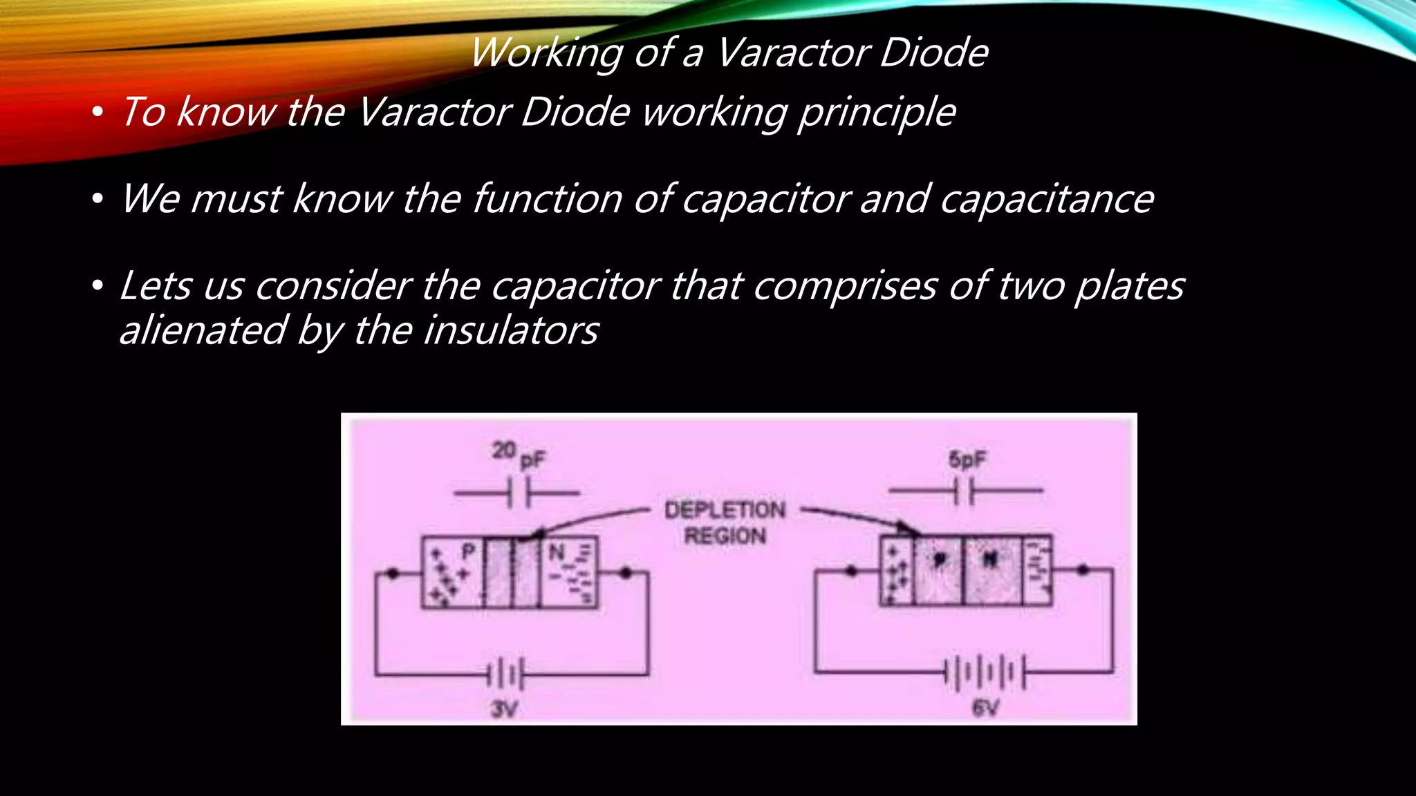
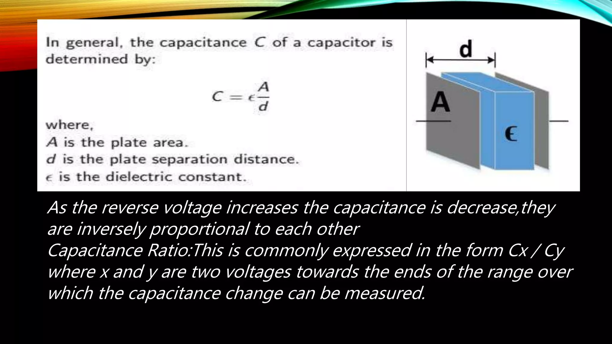
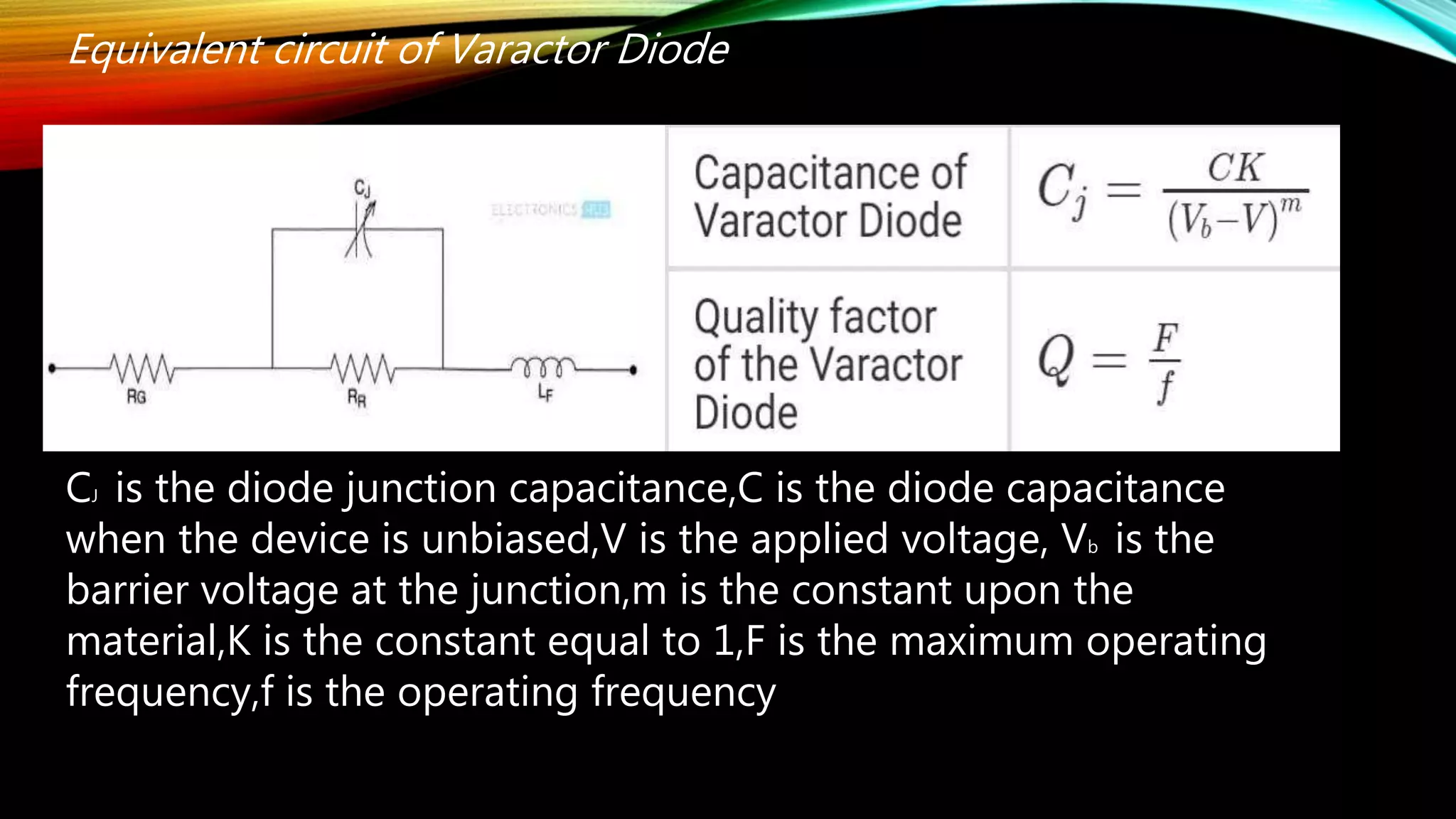
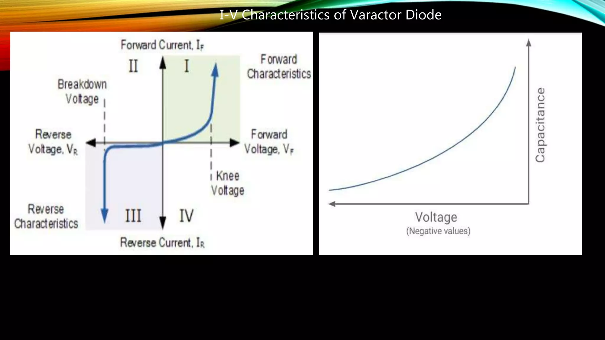
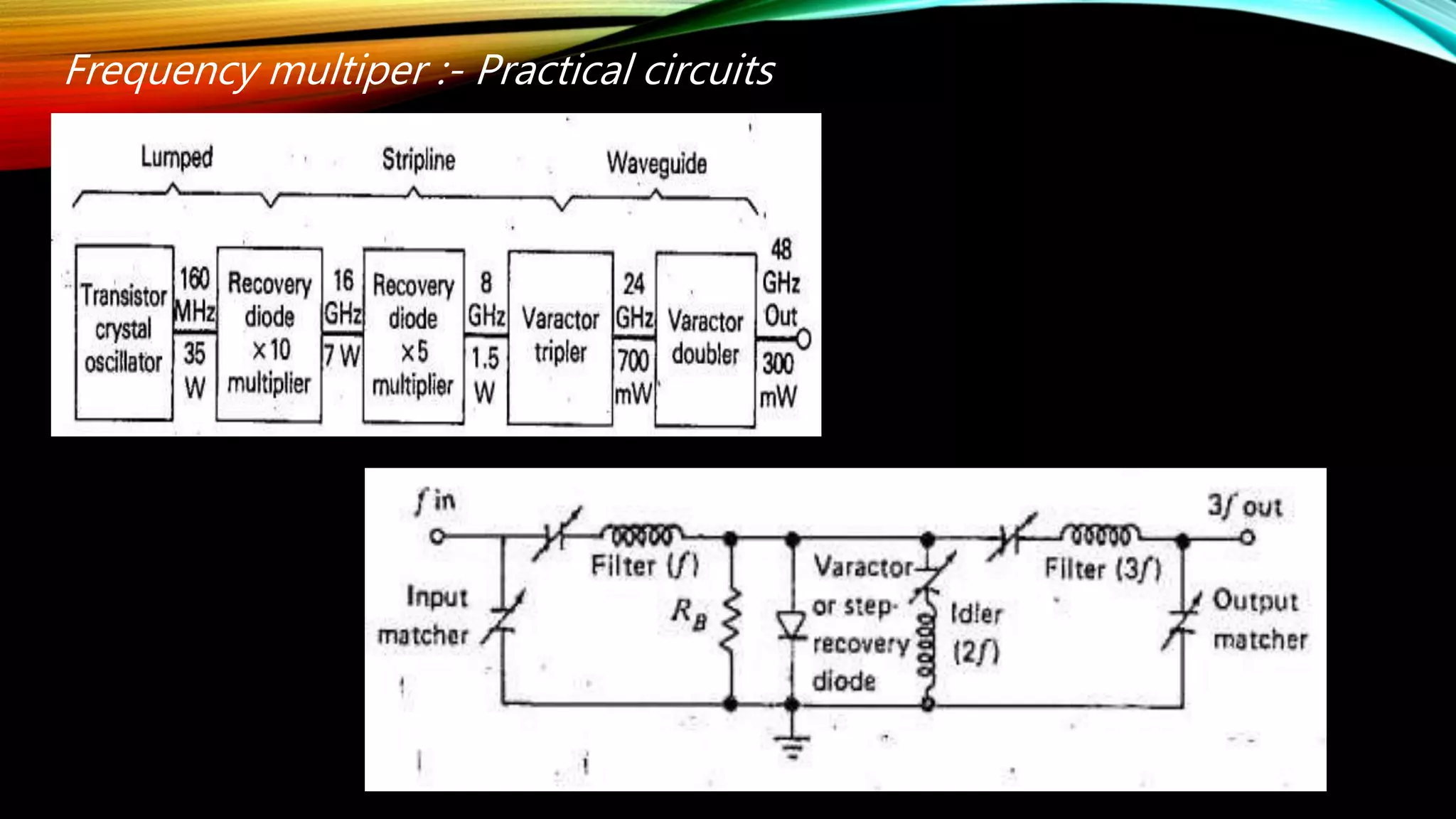
VIRENDRA THAKUR
SAP NO-40507190005
TOPIC- VARACTOR,STEP
RECOVERY DIODES AND
FREQUENCY MULTIPER
VARACTOR DIODE
A varactor diode is a P-N junction diode that changes its
capacitance and the series resistance as the bias applied to the
diode is varied The property of capacitance change is utilised to
achieve a change in the frequency or the phase of an electrical
circuit Let’s we have a overview of a varactor diode,that includes
working, construction, application and characteristics
What is a Varactor Diode?
• Varactor Diode is a one kind of semiconductor microwave solid-
state device
• Varactor diodes are also named as Varicap diodes
• The outcomes of the variable capacitance can be showed by the
normal P-N junction diodes
• These diode are chosen for giving the desired capacitance
changes as they are special types of diodes
• Varactor Diode are specially fabricated and optimised such that
they permits a high range of changes in capacitance
Symbol of Varactor Diode
• The symbol of the Varactor Diode look like a common PN
junction diode
• It inculdes two terminals namely the cathode and anode
• At one end of this diode is inbuilt with lines that specifies the
capacitor symbol
Materials and construction
• This Varactor Diode is
made of gallium
arsenide
• GaAs has advantage as
a higher maximum
operating frequency
and better functioning
at the lowest
temperature
• Both the advantages
are due to the higher
mobility of charge
carriers exhibited by
GaAs
Working of a Varactor Diode
• To know the Varactor Diode working principle
• We must know the function of capacitor and capacitance
• Lets us consider the capacitor that comprises of two plates
alienated by the insulators
• The capacitance of a capacitor is directly proportional to the
region of the terminals
• When the diode is in the reverse biased mode
• Where the two regions of P-type and N-type are able to conduct
and thus can be treated as two terminals
• The depletion area between the P-type and N-type regions can be
considered as insulating dielectric
• The volume of the depletion region of the diode varies with thd
changes in reverse bias
• If the reverse voltage of the diode is increased,then the size of the
depletion region increase
As the reverse voltage increases the capacitance is decrease,they
are inversely proportional to each other
Capacitance Ratio:This is commonly expressed in the form Cx / Cy
where x and y are two voltages towards the ends of the range over
which the capacitance change can be measured.
Equivalent circuit of Varactor Diode
CJ is the diode junction capacitance,C is the diode capacitance
when the device is unbiased,V is the applied voltage, Vb is the
barrier voltage at the junction,m is the constant upon the
material,K is the constant equal to 1,F is the maximum operating
frequency,f is the operating frequency
I-V Characteristics of Varactor Diode
Step Recovery Diode
• A Step Recovery Diode or snap-off Varactor is widely used in
microwave frequency multiper circuits
• A step recovery diode is a P-N junction diode made with gallium
arsenide or silicon
• When it is forward biased,it conducts like any diode,but charge is
stored in the depletion region
• When reverse bias is applied,the charge keep the diode on
momentarily and then turns off the abruptly
• This is snap off produces a high intensity pulse that is rich in
harmonics
Symbol of step recovery diode
• It’s also possible to use these diode without
tuned output circuit,to produce multiple
harmonic in so called Comb generators
• A comb generator is a signal generator that
produces multiple harmonics of its input signal.
Frequency multiper :- Practical circuits

Varactor, step recovery diodes and frequency multiplier

  • 1.
    VIRENDRA THAKUR SAP NO-40507190005 TOPIC-VARACTOR,STEP RECOVERY DIODES AND FREQUENCY MULTIPER
  • 2.
    VARACTOR DIODE A varactordiode is a P-N junction diode that changes its capacitance and the series resistance as the bias applied to the diode is varied The property of capacitance change is utilised to achieve a change in the frequency or the phase of an electrical circuit Let’s we have a overview of a varactor diode,that includes working, construction, application and characteristics
  • 3.
    What is aVaractor Diode? • Varactor Diode is a one kind of semiconductor microwave solid- state device • Varactor diodes are also named as Varicap diodes • The outcomes of the variable capacitance can be showed by the normal P-N junction diodes • These diode are chosen for giving the desired capacitance changes as they are special types of diodes • Varactor Diode are specially fabricated and optimised such that they permits a high range of changes in capacitance
  • 4.
    Symbol of VaractorDiode • The symbol of the Varactor Diode look like a common PN junction diode • It inculdes two terminals namely the cathode and anode • At one end of this diode is inbuilt with lines that specifies the capacitor symbol
  • 5.
    Materials and construction •This Varactor Diode is made of gallium arsenide • GaAs has advantage as a higher maximum operating frequency and better functioning at the lowest temperature • Both the advantages are due to the higher mobility of charge carriers exhibited by GaAs
  • 6.
    Working of aVaractor Diode • To know the Varactor Diode working principle • We must know the function of capacitor and capacitance • Lets us consider the capacitor that comprises of two plates alienated by the insulators
  • 7.
    • The capacitanceof a capacitor is directly proportional to the region of the terminals • When the diode is in the reverse biased mode • Where the two regions of P-type and N-type are able to conduct and thus can be treated as two terminals • The depletion area between the P-type and N-type regions can be considered as insulating dielectric • The volume of the depletion region of the diode varies with thd changes in reverse bias • If the reverse voltage of the diode is increased,then the size of the depletion region increase
  • 8.
    As the reversevoltage increases the capacitance is decrease,they are inversely proportional to each other Capacitance Ratio:This is commonly expressed in the form Cx / Cy where x and y are two voltages towards the ends of the range over which the capacitance change can be measured.
  • 9.
    Equivalent circuit ofVaractor Diode CJ is the diode junction capacitance,C is the diode capacitance when the device is unbiased,V is the applied voltage, Vb is the barrier voltage at the junction,m is the constant upon the material,K is the constant equal to 1,F is the maximum operating frequency,f is the operating frequency
  • 10.
    I-V Characteristics ofVaractor Diode
  • 11.
    Step Recovery Diode •A Step Recovery Diode or snap-off Varactor is widely used in microwave frequency multiper circuits • A step recovery diode is a P-N junction diode made with gallium arsenide or silicon • When it is forward biased,it conducts like any diode,but charge is stored in the depletion region • When reverse bias is applied,the charge keep the diode on momentarily and then turns off the abruptly • This is snap off produces a high intensity pulse that is rich in harmonics
  • 12.
    Symbol of steprecovery diode • It’s also possible to use these diode without tuned output circuit,to produce multiple harmonic in so called Comb generators • A comb generator is a signal generator that produces multiple harmonics of its input signal.
  • 13.
    Frequency multiper :-Practical circuits