Downloaded 879 times

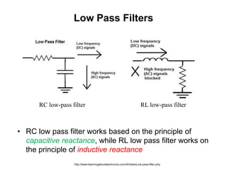
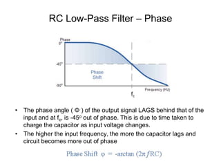
![RC and RL High-Pass Filter Circuits
Switching elements results in a High-Pass Filter.
co co
1
or [Hz]
2 2
R
f f
RC L
f (Hz)fco
actual
passbandreject-band
“ideal”
cutoff frequency
o
s
V
V
0 dB
–3 dB](https://image.slidesharecdn.com/passive-filters-150314035710-conversion-gate01/85/Passive-filters-16-320.jpg)
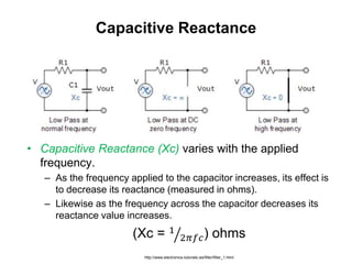
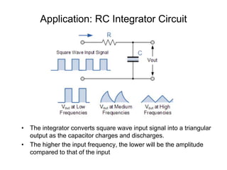
![Example
What is the cutoff frequency for this filter?
Given:
8.2
0.0033
R k
C F
W
co
coor [Hz]
2
RC
f
RC
co 5.88 kHzf ](https://image.slidesharecdn.com/passive-filters-150314035710-conversion-gate01/85/Passive-filters-19-320.jpg)
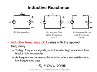
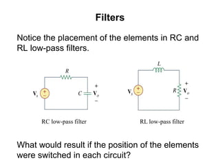
![EXAMPLE – RL Low Pass Filter
Design a series RL low-pass filter to filter out any noise above 10 Hz.
R and L cannot be specified independently to generate a value for fco = 10 Hz
or co = 2fco. Therefore, let us choose L=100 mH. Then,
3
(2 )(10)(100 10 ) 6.28coR L
W
2 2 22
20
( )
400
R
L
o s s
R
L
V V V
f(Hz) |Vs| |Vo|
1 1.0 0.995
10 1.0 0.707
60 1.0 0.164
co co2
1
which implies: or [Hz]
2
1
o
s
R R
f
L LL
R
V
V](https://image.slidesharecdn.com/passive-filters-150314035710-conversion-gate01/85/Passive-filters-21-320.jpg)
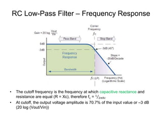
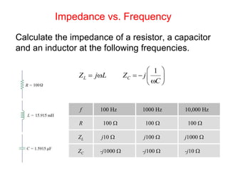
![Example
What resistor value R will produce a cutoff frequency of 3.4 kHz
with a 0.047 mF capacitor? Is this a high-pass or low-pass filter?
co
co
1
[Hz]
2
1
R=
2
f
RC
C f
1004R W
This is a High-Pass Filter](https://image.slidesharecdn.com/passive-filters-150314035710-conversion-gate01/85/Passive-filters-23-320.jpg)

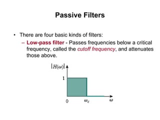
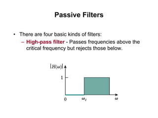
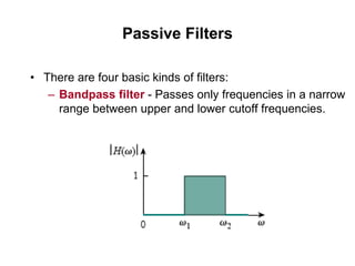
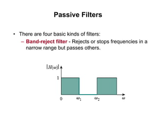
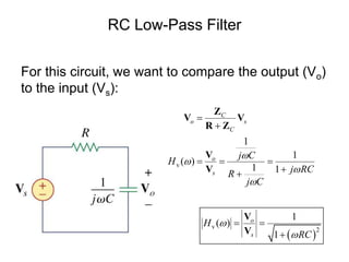
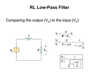
This document discusses passive filters, which are composed only of passive components like resistors, capacitors, and inductors. There are four basic types of passive filters: low-pass filters, which pass frequencies below a cutoff frequency; high-pass filters, which pass frequencies above a cutoff frequency; bandpass filters, which pass a narrow range of frequencies between upper and lower cutoff frequencies; and band-reject filters, which reject a narrow range of frequencies but pass others. The document provides examples of RC and RL low-pass and high-pass filter circuits and discusses how their frequency response depends on the component values.


![Lecture-6-[Passive Filter].pdfmmmmmmmmmmmmmmmmmmmm](https://cdn.slidesharecdn.com/ss_thumbnails/lecture-6-passivefilter-251130051517-4644d20e-thumbnail.jpg?width=640&height=640&fit=bounds)