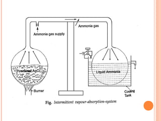
SIMPLE VAPOR-
ABSORPTION
REFRIGERATION
SYSTEM
Manmeet Singh
INTRODUCTI
ON
 The major drawback of the vapour compression refrigeration
system is that it requires large volume of refrigerant vapour
which requires large mechanical power for its operation.
 If some methods are used to reduce this volume before
compression, there would be considerable reduction in weight
of the system and power requirement for its operation.
 Heat energy can be used instead of work for producing
refrigeration because it gives high COP of the system with
machine operated with supply of work energy.
 The absorption system differs fundamentally from vapour
in the method of employed forcompression system only
compressing the refrigerant.
 In the absorption system, the compressor is replaced by an
absorber, generator and a pump.
 A French Scientist Ferdinand Cane
developed the first
absorption refrigeration machine in early 1860.
 Nowadays, units are developed upto 1500 tons capacity.
 The units which are generally used for
air conditioning purposes are available from 100 tons
capacity .
PRINCIPLE OF ABSORPTIN
SYSTEM
 There is the peculiar property of some substances to have
affinity for another substances at some temperature and
pressure conditions and less affinity at another conditions.
This idea for the working principle of a vapour absorption
system was generated by Michael Faraday in 1824.
He knew that silver chloride (AgCl)m a white powder , had a
property of absorbing large amount of ammonia gas at the
normal temperature and pressure.
 Two chambers are combined with the help of a tube.
 The white powder was kept inside the first chamber to which ammonia
gas was supplied and sealed.
 The powder was heated up while other end was cooled
using circulating
water.
 Liquid ammonia was obtained in the cool end of the apparatus. After
stopping heat, it was observed that, the liquid ammonia instead of sitting
there, started boiling( bubbles produced) and vapour was reabsorbed by
the white powder.
 Upon touching the boiling end , it was astonished to find that the vessel
was very cold.
 He repeated the experiments and cooling was observed again.
 This led to invention of the intermittent Vapour
absorption system having solid as an absorber.
REFRIGERANT ABSORBER STATE OF
ABSORBER
AMMONIA WATER LIQUID
AMMONIA SODIUMTHIOCYNATE SOLID
AMMONIA LITHIUM NITRATE SOLID
AMMONIA CALCIUM CHLORIDE SOLID
AMMONIA ISOBUTANE SOLID
WATER LITHIUM BROMIDE SOLID
WATER LITHIUM CHLORIDE SOLID
METHYL
CHLORIDE
DIMETHYL ETHER OF TETRA
ETHYLENE GLYCOL
LIQUID
REFRIGERANT –ABSORBER PAIRS
SYSTEM
SIMPLE VAPOR ABSORPTION REFRIGERATION
SYSTEM
@Point 1
-low temperature and low pressure
refrigerant vapour from evaporator at state 1
enters the absorber and is absorbed by solution
weak in refrigerant (state 8) .
The heat of absorption (Qa
) is rejected to an
external heat sink at T∞
.
SIMPLE VAPOR ABSORPTION REFRIGERATION
SYSTEM
@Point 2
-The solution, rich in refrigerant is pumped to
the generator pressure (Pg
) by the solution pump
(state 3). The pressurized solution gets heated up
sensibly as it flows through the solution heat
exchanger by extracting heat from hot solution
coming from generator (state 4).
SIMPLE VAPOR ABSORPTION REFRIGERATION
SYSTEM
@Point 5
-Heat is supplied to this solution from an
external heat source in the generator (Qg
at Tg
), as a
result refrigerant vapour is generated (absorbent
may also boil to give off vapour in case of ammonia-
water systems) at state 5.
This high-pressure refrigerant vapour condenses in
the condenser by rejecting heat of condensation to
the external heat sink (Qc
at T∞
) and leaves the
condenser as a high pressure liquid (state 9).
SIMPLE VAPOR ABSORPTION REFRIGERATION
SYSTEM
@Point 10
- the high pressure refrigerant liquid is
throttled in the expansion device to evaporator
pressure Pe
from where it enters the evaporator,
extracts heat from low temperature heat source (Qe
at Te
) and leaves the evaporator as vapour at state
1, completing a cycle.
SIMPLE VAPOR ABSORPTION REFRIGERATION
SYSTEM
@Point 6
- The hot solution that is weak in refrigerant
(state 6) leaves the generator at high temperature
and is cooled sensibly by rejecting heat to the
solution going to the generator in the solution heat
exchanger (state 7).
Then it is throttled to the evaporator pressure in
the throttle valve (state 8), from where it enters the
absorber to complete the cycle.
COP FOR IDEAL VAPOR ABSORPTION
REFRIGERATION SYSTEM
COP FOR IDEAL VAPOR ABSORPTION
REFRIGERATION SYSTEM
 Absorption system requires a relatively large
amount of low-grade thermal energy at generator
temperature to generate refrigerant vapour from
the solution in generator. Thus while the energy
input is in the form of mechanical energy in
vapour compression refrigeration systems, it is
mainly in the form of thermal energy in case of
absorption systems.
COP FOR IDEAL VAPOR ABSORPTION
REFRIGERATION SYSTEM
 The solution pump work is often negligible
compared to the generator heat input. Thus the
COPs for compression and absorption systems are
given by:
COP FOR IDEAL VAPOR ABSORPTION
REFRIGERATION SYSTEM
 Thus absorption systems are advantageous where
a large quantity of low-grade thermal energy is
available freely at required temperature.
However, it will be seen that for the refrigeration
and heat rejection temperatures, the COP of
vapour compression refrigeration system will be
much higher than the COP of an absorption
system as a high grade mechanical energy is used
in the former, while a low-grade thermal energy is
used in the latter.
COP FOR IDEAL VAPOR ABSORPTION
REFRIGERATION SYSTEM
 However, comparing these systems based on COPs
is not fully justified, as mechanical energy is more
expensive than thermal energy. Hence, sometimes
the second law (or exergetic) efficiency is used to
compare different refrigeration systems. It is seen
that the second law (or exergetic) efficiency of
absorption system is of the same order as that of a
compression system.
MAXIMUM COP FOR IDEAL VAPOR ABSORPTION
REFRIGERATION SYSTEM
MAXIMUM COP FOR IDEAL VAPOR ABSORPTION
REFRIGERATION SYSTEM
From first law of thermodynamics,
Where
Qe
is the heat transferred to the absorption system
at evaporator temperature Te
,
Qg
is the heat transferred to the generator of the
absorption system at temperature Tg
,
Qa+c
is the heat transferred from the absorber and
condenser of the absorption system at
temperature To
and
Wp
is the work input to the solution pump.
MAXIMUM COP FOR IDEAL VAPOR ABSORPTION
REFRIGERATION SYSTEM
 If we assume that heat rejection at the absorber
and condenser takes place at same external heat
sink temperature To
, then a vapour absorption
refrigeration system operates between three
temperature levels, Tg
, To
and Te
.
MAXIMUM COP FOR IDEAL VAPOR ABSORPTION
REFRIGERATION SYSTEM
The maximum possible COP of an ideal VARS
system is given by:
MAXIMUM COP FOR IDEAL VAPOR ABSORPTION
REFRIGERATION SYSTEM
Thus the ideal COP is only a function of operating
temperatures similar to Carnot system. It can be
seen from the above expression that the ideal COP
of VARS system is equal to the product of
efficiency of a Carnot heat engine operating
between Tg
and To
and COP of a Carnot
refrigeration system operating between To
and Te
,
MAXIMUM COP FOR IDEAL VAPOR ABSORPTION
REFRIGERATION SYSTEM
Thus an ideal vapour absorption refrigeration
system can be considered to be a combined system
consisting of a Carnot heat engine and a Carnot
refrigerator as shown in Fig.14.4. Thus the COP of
an ideal VARS increases as generator temperature
(Tg
) and evaporator temperature (Te
) increase and
heat rejection temperature (To
) decreases.
However, the COP of actual VARS will be much
less than that of an ideal VARS due to various
internal and external irreversibilities present in
actual systems.
PRACTICAL VAPOR ABSORPTION REFRIGERATION
SYSTEM
 A practical VARS has 3 additional parts :
ANALYSER
RECTIFIER
HEAT EXCHANGER
PRACTICAL VAPOR – ABSORPTION
REFRIGERATION SYSTEM
THREE FLUID VAPOR
ABSORPTION SYSTEM-
ELECTROLUX SYSTEM
 1. Hydrogen enters the pipe with liquid ammonia (or
lithium bromide solution)
2. Ammonia and hydrogen enter the inner
compartment of the refrigerator. An increase in volume
causes a decrease in the partial pressure of the liquid
ammonia. The ammonia evaporates, requiring energy
to overcome the ΔHVap. The required energy is drawn
from the interior of the refrigerator, thus cooling it.
3. Ammonia and hydrogen return from the inner
compartment, ammonia returns to absorber and
dissolves in water. Hydrogen is free to rise upwards.
4. Ammonia gas condensation (passive cooling).
5. Hot ammonia (gas).
6. Heat insulation and distillation of ammonia gas
from water.
7. Heat source (electric).
8. Absorber vessel (water and ammonia solution).
ROLE OF HYDROGEN
ADVANTAGES THREE FLUID
SYSTEM
DISADVANTAGES THREE FLUID
SYSTEM
ABSORPTION
REFRIGERATION
SYSTEMS BASED ON
WATER-LITHIUM BROMIDE
PAIR
VARS BASED ON H2O – LIBR PAIR
 Vapour absorption refrigeration systems using
water-lithium bromide pair are extensively used
in large capacity air conditioning systems.
 In these systems water is used as refrigerant and
a solution of lithium bromide in water is used as
absorbent.
 Since water is used as refrigerant, using these
systems it is not possible to provide refrigeration
at sub-zero temperatures. Hence it is used only
in applications requiring refrigeration at
temperatures above 0o
C.
VARS BASED ON H2O – LIBR PAIR
 Hence these systems are used for air conditioning
applications. The analysis of this system is
relatively easy as the vapour generated in the
generator is almost pure refrigerant (water),
unlike ammonia-water systems where both
ammonia and water vapour are generated in the
generator.
STEADY FLOW ANALYSIS OF WATER-
LITHIUM BROMIDE SYSTEMS
A steady flow analysis of the system is carried out with
the following assumptions:
i. Steady state and steady flow
ii. Changes in potential and kinetic energies across
each component are negligible
iii. No pressure drops due to friction
iv. Only pure refrigerant boils in the generator.
The nomenclature followed is:
m= mass flow rate of refrigerant, kg/s
mss= mass flow rate of strong solution (rich in LiBr),
kg/s
mws= mass flow rate of weak solution (weak in LiBr),
kg/s
Circulation ratio (λ)
-defined as the ratio of
strong solution
flow rate to
refrigerant
flow rate.
It is given by:
λ = mss/m
@Condenser
m1 = m2 = m3
Qc = m(h1 – h2)
Pc = Psat (TC)
where TC is the
condenser
temperature
@Expansion valve (refrigerant):
m2 = m3 = m
h2 = h3
@Evaporator:
m3 = m4 = m
QE = m(h4 – h3)
PE = PSAT(TE)
where TE is the
evaporator
temperature
@Absorber
From total mass balance:
m + mss = mws
but mss = λm,
mws = (1+λ)m
QA=mh4+ λmh10
- (1+λ)mh5
@Solution pump
m5 = m6 = mws
Wp = mws(h6-h5)
=(1+λ)m(h6-h5)
Even though
the solution pump
work is small it is
still required in the
selection of
suitable pump.
@Generator
m7 = m8 +m1
Heat input to the
generator is given by:
QG=mh1+λmh8
-(1+λ)mh7
@Solution heat exchanger
m6 = m7 = mws
m8 = m9 = mss
heat transfer
rate in the solution
heat exchanger, Q
is given by:
QHX = (1+λ)m(h7-h6)
=λm(h8-h9)
@Solution expansion valve
m9 = m10 = mws
h9 = h10
The COP of the
system is given by:
ADVANTAGES OVER VAPOUR
COMPRESSION SYSTEM
 As there is no moving parts in the entire system, the operation
is essentially quiet and subjected to a very little wear, so that
the maintenance cost is low.
 The pump motor is quite small compared with the compressor
motor.
 Vapour absorption system is used the thermal energy, they
can be used in places, where electric power is hard to obtain.
 Absorption unit can be built in capacities well above 1000 tons
 Space requirement is less.
PROPERTIES OF GOOD ABSORBER
PROPERTIES OF GOOD
REFRIGERANT
SAMPLE PROBLEM IN SIMPLE VARS
9. The operating temperatures of a single stage
vapour absorption refrigeration system are:
generator: 90o
C; condenser and absorber: 40o
C;
evaporator: 0o
C. The system has a refrigeration
capacity of 100 kW and the heat input to the
system is 160 kW. The solution pump work is
negligible.
a) Find the COP of the system and the total heat
rejection rate from the system.
b) An inventor claims that by improving the
design of all the components of the system he could
reduce the heat input to the system to 80 kW while
keeping the refrigeration capacity and operating
temperatures same as before. Examine the validity
of the claim.
SAMPLE PROBLEM IN SIMPLE VARS
 Solution:

Vapor absorption system

  • 1.
  • 2.
    INTRODUCTI ON  The majordrawback of the vapour compression refrigeration system is that it requires large volume of refrigerant vapour which requires large mechanical power for its operation.  If some methods are used to reduce this volume before compression, there would be considerable reduction in weight of the system and power requirement for its operation.  Heat energy can be used instead of work for producing refrigeration because it gives high COP of the system with machine operated with supply of work energy.
  • 3.
     The absorptionsystem differs fundamentally from vapour in the method of employed forcompression system only compressing the refrigerant.  In the absorption system, the compressor is replaced by an absorber, generator and a pump.  A French Scientist Ferdinand Cane developed the first absorption refrigeration machine in early 1860.  Nowadays, units are developed upto 1500 tons capacity.  The units which are generally used for air conditioning purposes are available from 100 tons capacity .
  • 4.
    PRINCIPLE OF ABSORPTIN SYSTEM There is the peculiar property of some substances to have affinity for another substances at some temperature and pressure conditions and less affinity at another conditions. This idea for the working principle of a vapour absorption system was generated by Michael Faraday in 1824. He knew that silver chloride (AgCl)m a white powder , had a property of absorbing large amount of ammonia gas at the normal temperature and pressure.
  • 6.
     Two chambersare combined with the help of a tube.  The white powder was kept inside the first chamber to which ammonia gas was supplied and sealed.  The powder was heated up while other end was cooled using circulating water.  Liquid ammonia was obtained in the cool end of the apparatus. After stopping heat, it was observed that, the liquid ammonia instead of sitting there, started boiling( bubbles produced) and vapour was reabsorbed by the white powder.  Upon touching the boiling end , it was astonished to find that the vessel was very cold.  He repeated the experiments and cooling was observed again.  This led to invention of the intermittent Vapour absorption system having solid as an absorber.
  • 7.
    REFRIGERANT ABSORBER STATEOF ABSORBER AMMONIA WATER LIQUID AMMONIA SODIUMTHIOCYNATE SOLID AMMONIA LITHIUM NITRATE SOLID AMMONIA CALCIUM CHLORIDE SOLID AMMONIA ISOBUTANE SOLID WATER LITHIUM BROMIDE SOLID WATER LITHIUM CHLORIDE SOLID METHYL CHLORIDE DIMETHYL ETHER OF TETRA ETHYLENE GLYCOL LIQUID REFRIGERANT –ABSORBER PAIRS
  • 8.
  • 11.
    SIMPLE VAPOR ABSORPTIONREFRIGERATION SYSTEM @Point 1 -low temperature and low pressure refrigerant vapour from evaporator at state 1 enters the absorber and is absorbed by solution weak in refrigerant (state 8) . The heat of absorption (Qa ) is rejected to an external heat sink at T∞ .
  • 12.
    SIMPLE VAPOR ABSORPTIONREFRIGERATION SYSTEM @Point 2 -The solution, rich in refrigerant is pumped to the generator pressure (Pg ) by the solution pump (state 3). The pressurized solution gets heated up sensibly as it flows through the solution heat exchanger by extracting heat from hot solution coming from generator (state 4).
  • 13.
    SIMPLE VAPOR ABSORPTIONREFRIGERATION SYSTEM @Point 5 -Heat is supplied to this solution from an external heat source in the generator (Qg at Tg ), as a result refrigerant vapour is generated (absorbent may also boil to give off vapour in case of ammonia- water systems) at state 5. This high-pressure refrigerant vapour condenses in the condenser by rejecting heat of condensation to the external heat sink (Qc at T∞ ) and leaves the condenser as a high pressure liquid (state 9).
  • 14.
    SIMPLE VAPOR ABSORPTIONREFRIGERATION SYSTEM @Point 10 - the high pressure refrigerant liquid is throttled in the expansion device to evaporator pressure Pe from where it enters the evaporator, extracts heat from low temperature heat source (Qe at Te ) and leaves the evaporator as vapour at state 1, completing a cycle.
  • 15.
    SIMPLE VAPOR ABSORPTIONREFRIGERATION SYSTEM @Point 6 - The hot solution that is weak in refrigerant (state 6) leaves the generator at high temperature and is cooled sensibly by rejecting heat to the solution going to the generator in the solution heat exchanger (state 7). Then it is throttled to the evaporator pressure in the throttle valve (state 8), from where it enters the absorber to complete the cycle.
  • 17.
    COP FOR IDEALVAPOR ABSORPTION REFRIGERATION SYSTEM
  • 18.
    COP FOR IDEALVAPOR ABSORPTION REFRIGERATION SYSTEM  Absorption system requires a relatively large amount of low-grade thermal energy at generator temperature to generate refrigerant vapour from the solution in generator. Thus while the energy input is in the form of mechanical energy in vapour compression refrigeration systems, it is mainly in the form of thermal energy in case of absorption systems.
  • 19.
    COP FOR IDEALVAPOR ABSORPTION REFRIGERATION SYSTEM  The solution pump work is often negligible compared to the generator heat input. Thus the COPs for compression and absorption systems are given by:
  • 20.
    COP FOR IDEALVAPOR ABSORPTION REFRIGERATION SYSTEM  Thus absorption systems are advantageous where a large quantity of low-grade thermal energy is available freely at required temperature. However, it will be seen that for the refrigeration and heat rejection temperatures, the COP of vapour compression refrigeration system will be much higher than the COP of an absorption system as a high grade mechanical energy is used in the former, while a low-grade thermal energy is used in the latter.
  • 21.
    COP FOR IDEALVAPOR ABSORPTION REFRIGERATION SYSTEM  However, comparing these systems based on COPs is not fully justified, as mechanical energy is more expensive than thermal energy. Hence, sometimes the second law (or exergetic) efficiency is used to compare different refrigeration systems. It is seen that the second law (or exergetic) efficiency of absorption system is of the same order as that of a compression system.
  • 22.
    MAXIMUM COP FORIDEAL VAPOR ABSORPTION REFRIGERATION SYSTEM
  • 23.
    MAXIMUM COP FORIDEAL VAPOR ABSORPTION REFRIGERATION SYSTEM From first law of thermodynamics, Where Qe is the heat transferred to the absorption system at evaporator temperature Te , Qg is the heat transferred to the generator of the absorption system at temperature Tg , Qa+c is the heat transferred from the absorber and condenser of the absorption system at temperature To and Wp is the work input to the solution pump.
  • 24.
    MAXIMUM COP FORIDEAL VAPOR ABSORPTION REFRIGERATION SYSTEM  If we assume that heat rejection at the absorber and condenser takes place at same external heat sink temperature To , then a vapour absorption refrigeration system operates between three temperature levels, Tg , To and Te .
  • 25.
    MAXIMUM COP FORIDEAL VAPOR ABSORPTION REFRIGERATION SYSTEM The maximum possible COP of an ideal VARS system is given by:
  • 26.
    MAXIMUM COP FORIDEAL VAPOR ABSORPTION REFRIGERATION SYSTEM Thus the ideal COP is only a function of operating temperatures similar to Carnot system. It can be seen from the above expression that the ideal COP of VARS system is equal to the product of efficiency of a Carnot heat engine operating between Tg and To and COP of a Carnot refrigeration system operating between To and Te ,
  • 27.
    MAXIMUM COP FORIDEAL VAPOR ABSORPTION REFRIGERATION SYSTEM Thus an ideal vapour absorption refrigeration system can be considered to be a combined system consisting of a Carnot heat engine and a Carnot refrigerator as shown in Fig.14.4. Thus the COP of an ideal VARS increases as generator temperature (Tg ) and evaporator temperature (Te ) increase and heat rejection temperature (To ) decreases. However, the COP of actual VARS will be much less than that of an ideal VARS due to various internal and external irreversibilities present in actual systems.
  • 29.
    PRACTICAL VAPOR ABSORPTIONREFRIGERATION SYSTEM  A practical VARS has 3 additional parts : ANALYSER RECTIFIER HEAT EXCHANGER
  • 30.
    PRACTICAL VAPOR –ABSORPTION REFRIGERATION SYSTEM
  • 31.
    THREE FLUID VAPOR ABSORPTIONSYSTEM- ELECTROLUX SYSTEM
  • 32.
     1. Hydrogenenters the pipe with liquid ammonia (or lithium bromide solution) 2. Ammonia and hydrogen enter the inner compartment of the refrigerator. An increase in volume causes a decrease in the partial pressure of the liquid ammonia. The ammonia evaporates, requiring energy to overcome the ΔHVap. The required energy is drawn from the interior of the refrigerator, thus cooling it. 3. Ammonia and hydrogen return from the inner compartment, ammonia returns to absorber and dissolves in water. Hydrogen is free to rise upwards. 4. Ammonia gas condensation (passive cooling). 5. Hot ammonia (gas). 6. Heat insulation and distillation of ammonia gas from water. 7. Heat source (electric). 8. Absorber vessel (water and ammonia solution).
  • 33.
  • 34.
  • 35.
  • 36.
  • 37.
    VARS BASED ONH2O – LIBR PAIR  Vapour absorption refrigeration systems using water-lithium bromide pair are extensively used in large capacity air conditioning systems.  In these systems water is used as refrigerant and a solution of lithium bromide in water is used as absorbent.  Since water is used as refrigerant, using these systems it is not possible to provide refrigeration at sub-zero temperatures. Hence it is used only in applications requiring refrigeration at temperatures above 0o C.
  • 38.
    VARS BASED ONH2O – LIBR PAIR  Hence these systems are used for air conditioning applications. The analysis of this system is relatively easy as the vapour generated in the generator is almost pure refrigerant (water), unlike ammonia-water systems where both ammonia and water vapour are generated in the generator.
  • 42.
    STEADY FLOW ANALYSISOF WATER- LITHIUM BROMIDE SYSTEMS A steady flow analysis of the system is carried out with the following assumptions: i. Steady state and steady flow ii. Changes in potential and kinetic energies across each component are negligible iii. No pressure drops due to friction iv. Only pure refrigerant boils in the generator. The nomenclature followed is: m= mass flow rate of refrigerant, kg/s mss= mass flow rate of strong solution (rich in LiBr), kg/s mws= mass flow rate of weak solution (weak in LiBr), kg/s
  • 43.
    Circulation ratio (λ) -definedas the ratio of strong solution flow rate to refrigerant flow rate. It is given by: λ = mss/m
  • 44.
    @Condenser m1 = m2= m3 Qc = m(h1 – h2) Pc = Psat (TC) where TC is the condenser temperature
  • 45.
    @Expansion valve (refrigerant): m2= m3 = m h2 = h3 @Evaporator: m3 = m4 = m QE = m(h4 – h3) PE = PSAT(TE) where TE is the evaporator temperature
  • 46.
    @Absorber From total massbalance: m + mss = mws but mss = λm, mws = (1+λ)m QA=mh4+ λmh10 - (1+λ)mh5
  • 47.
    @Solution pump m5 =m6 = mws Wp = mws(h6-h5) =(1+λ)m(h6-h5) Even though the solution pump work is small it is still required in the selection of suitable pump.
  • 48.
    @Generator m7 = m8+m1 Heat input to the generator is given by: QG=mh1+λmh8 -(1+λ)mh7
  • 49.
    @Solution heat exchanger m6= m7 = mws m8 = m9 = mss heat transfer rate in the solution heat exchanger, Q is given by: QHX = (1+λ)m(h7-h6) =λm(h8-h9)
  • 50.
    @Solution expansion valve m9= m10 = mws h9 = h10 The COP of the system is given by:
  • 51.
    ADVANTAGES OVER VAPOUR COMPRESSIONSYSTEM  As there is no moving parts in the entire system, the operation is essentially quiet and subjected to a very little wear, so that the maintenance cost is low.  The pump motor is quite small compared with the compressor motor.  Vapour absorption system is used the thermal energy, they can be used in places, where electric power is hard to obtain.  Absorption unit can be built in capacities well above 1000 tons  Space requirement is less.
  • 52.
  • 53.
  • 54.
    SAMPLE PROBLEM INSIMPLE VARS 9. The operating temperatures of a single stage vapour absorption refrigeration system are: generator: 90o C; condenser and absorber: 40o C; evaporator: 0o C. The system has a refrigeration capacity of 100 kW and the heat input to the system is 160 kW. The solution pump work is negligible. a) Find the COP of the system and the total heat rejection rate from the system. b) An inventor claims that by improving the design of all the components of the system he could reduce the heat input to the system to 80 kW while keeping the refrigeration capacity and operating temperatures same as before. Examine the validity of the claim.
  • 55.
    SAMPLE PROBLEM INSIMPLE VARS  Solution:

Editor's Notes