Air conditioning system of car or buses works on principle of vapor absorption cycle of refrigeration VAR . This system reduces the fuel economy of fuel of vehicle. When vehicle moving with air conditioning, it consumes more amount of fuel than vehicle rubs without AC, typically, it consumes 15 to 20 more amount of fuel. Exhaust gases coming from engine of vehicle have temperature ranges to 300 to 400 degree centigrade at full load it carries 25 to 30 of heat supplied by fuel. For A.C. of an automobile, the heat of exhaust gases is utilized to run vapor absorption refrigeration cycle instead of vapour compression refrigeration system. Resulting, it improves fuel economy of A. C. heavy vehicle. In this project try to integrate the vapor absorption refrigeration system with car or bus or heavy vehicle engine exhaust. Comparative study has been carried out when car running with VCR and vapor absorption system of refrigeration. Dr. M. Sampath Kumar | Karthik Payam | Rajesh Medi | Srikanth Chennam | Aditya Mothukuri ""Generation of Air Conditioning by using Exhaust Gases and Cooling Water of an Automobile Engine"" Published in International Journal of Trend in Scientific Research and Development (ijtsrd), ISSN: 2456-6470, Volume-3 | Issue-3 , April 2019, URL: https://www.ijtsrd.com/papers/ijtsrd23318.pdf
Paper URL: https://www.ijtsrd.com/engineering/mechanical-engineering/23318/generation-of-air-conditioning-by-using-exhaust-gases-and-cooling-water-of-an-automobile-engine/dr-m-sampath-kumar
Automobile air-conditioning is a necessity of present life. vapour compression refrigeration cycle used in modern automobile and refrigerant 134a are available in automobile. The compressor of automobile air-conditioning is run by engine crankshaft, which reduces the mileage of the
automobile. Waste heat recovery of internal combustion engine are two type, one is direct type or thermal energy or waste heat direct converted into electrical energy by see back effect and other is indirect type waste heat is used for rankine cycle ,sterling cycle or refrigeration cycle.
Cooling of a truck cabin by vapour absorption refrigeration system using engi...eSAT Publishing House
IJRET : International Journal of Research in Engineering and Technology is an international peer reviewed, online journal published by eSAT Publishing House for the enhancement of research in various disciplines of Engineering and Technology. The aim and scope of the journal is to provide an academic medium and an important reference for the advancement and dissemination of research results that support high-level learning, teaching and research in the fields of Engineering and Technology. We bring together Scientists, Academician, Field Engineers, Scholars and Students of related fields of Engineering and Technology
The air conditioning system of automobiles in today’s world uses “Vapour Compression
Refrigerant System” (VCRS) which absorbs and removes heat from the interior of the vehicle. The
system utilizes power from engine shaft as the input power to drive the compressor of the refrigerant
system. The loss of power of the engine to run the VCR system can be neglected by utilizing another
refrigeration system i.e. a “Vapour Absorption Refrigerant System”. In a Vapour Absorption
Refrigerant System, a physicochemical process replaces the mechanical process of the Vapour
Compression Refrigerant System by using energy in the form of heat rather than mechanical work.
The experimental work to utilize the waste heat from exhaust gases from an engine for the vapour
absorption refrigerant system with R-134a as refrigerant and DMF as absorbent. The experimental
results indicated that vehicle performance enhances, noise reduces, maintenance becomes easier, and
highly reliable. The data obtained from experimentation is presented analyzed in this paper.
SOLAR POWER VAPOUR ABSORPTION REFRIGERATION SYSTEMaj12345ay
USE OF SOLAR POWER IN REFRIGERATION SYSTEM
The power incident from the sun to the earth has very much amount of energy that the present consumption rate of all the commercial and general uses. We utilize only 0.1% of total incident sun energy on the surface of earth. Thus solar energy can fulfill our present as well as future needs of energy. That is a reason it called renewable sources of energy. It is also environmental clean source of energy and available at whole part of world where people live. Using of solar energy in the field of refrigeration and air conditioning system it become very economical.
In our project we provide solar heat in generator for heating purpose of vapor compression refrigeration system.
For past few decades, energy has played a prominent role in the development of technology and economy. Energy has now become inevitable factor for production as well. The objective of this project is to develop an environment friendly vapour absorption system. Vapour absorption system uses heat energy, instead of mechanical energy as in vapour compression system, in order to change the condition of refrigerant required for the operation of the cycle. R 717(NH3) and water are used as working fluids in this system. The basic idea of this project is derived from the solar heating panel to obtain heat energy, instead of using any conventional source of heat energy. In this project various observations are done by varying operating conditions related to heat source, condenser, absorber and evaporator temperatures. The drawback of this system is that, it remains idle in the cloudy weather conditions.
COMPONENTS USED IN SOLAR POWERED AQUA-AMMONIA VAPOUR ABSORPTION SYSTEM
• ABSORBER
• PUMP
• HEAT EXCHANGER
• GENERATOR
• SOLAR PANEL
• CONDENSER
• EXPANSION VALVE
• EVAPORATOR
• DC BATTERY
• FAN
Design and Fabrication of Vapour Absorption Refrigeration System [Libr-H20]IJMER
Most of the energies are utilized by the industries due to depletion of fossil fuels and
increasing the fuel price to exploit the maximum presented energy from the waste heat source. The
industry which utilizes steam turbine exhaust carries a considerable amount of thermal energy. This
energy can be set in to positive use as a heat source for vapour absorption system to serves as cooling
system. This paper illustrates the thermal and fiscal advantages of using single effect lithium bromide
water absorption by means of waste heat. The objective of this work is to hypothetical design of lithium
bromide water absorption Refrigeration system using waste heat from any industry steam turbine
exhaust
A Review on Performance Comparison of VCRs &VARsdbpublications
Vapour Absorption Refrigeration Systems (VARS) and vapour compression refrigeration system (VCRS) both are widely used for refrigeration purpose. The major differences in both the system are in vapour compression refrigeration systems the input supply is compressor work which is high grade of energy whereas in vapour absorption systems main input is heat supply in the generator which is low grade energy. Energy is an essential requirement for the economic development of any country, so our main aim is to save energy, unless VCRS have high performance future scope is VARS are primarily used in large commercial and industrial installations .In this paper discusses the various methods for increasing the performance of both systems so this paper focuses on the suitability of both systems.
A Review Paper on Design of Generator in Vapour Absorption Refrigeration Systemijtsrd
In vapour absorbtion refrigeration system an absorber, a pump, a generator and a pressure reducing valve replace the compressor. We can also operate the generator with low thermal energy by exhaust heat of IC engine. The fossil fuel remain main source of energy but contribute a tremendous amount of pollutants in the environment leading to global warming ,so for the purpose of refrigerator and air conditioning a vapour absorption refrigeration system could be used. this system utilizes the wasteful heat from heavy vehicle exhaust and work on VARS which provides the cooling and reducing various costs like fuel and maintenance. The research has been done in order to recover maximum waste heat and then analyzing the system performance. Through this system the researchers has tried to find out the maximum COP. It has been found by research that generator temperature has the most effect on the release of the system. Alok Kumar Gupta | Laraib Ahamad | Prabhat Kumar Yadav | Paurush Pandit "A Review Paper on Design of Generator in Vapour Absorption Refrigeration System" Published in International Journal of Trend in Scientific Research and Development (ijtsrd), ISSN: 2456-6470, Volume-4 | Issue-4 , June 2020, URL: https://www.ijtsrd.com/papers/ijtsrd31321.pdf Paper Url :https://www.ijtsrd.com/engineering/mechanical-engineering/31321/a-review-paper-on-design-of-generator-in-vapour-absorption-refrigeration-system/alok-kumar-gupta
vapor absorption system,three fluid vapor absorption system,water and ammonia vapor absorption system water and lithium bromide vapor absorption system
International Journal of Engineering Research and Applications (IJERA) is an open access online peer reviewed international journal that publishes research and review articles in the fields of Computer Science, Neural Networks, Electrical Engineering, Software Engineering, Information Technology, Mechanical Engineering, Chemical Engineering, Plastic Engineering, Food Technology, Textile Engineering, Nano Technology & science, Power Electronics, Electronics & Communication Engineering, Computational mathematics, Image processing, Civil Engineering, Structural Engineering, Environmental Engineering, VLSI Testing & Low Power VLSI Design etc.
International Journal of Engineering Research and Applications (IJERA) is an open access online peer reviewed international journal that publishes research and review articles in the fields of Computer Science, Neural Networks, Electrical Engineering, Software Engineering, Information Technology, Mechanical Engineering, Chemical Engineering, Plastic Engineering, Food Technology, Textile Engineering, Nano Technology & science, Power Electronics, Electronics & Communication Engineering, Computational mathematics, Image processing, Civil Engineering, Structural Engineering, Environmental Engineering, VLSI Testing & Low Power VLSI Design etc.
It will help to the students of Mechanical Engineering. These notes are according to HVAC Subject. Some important topics are here for your good understanding. These are written in easy language, u can understand easily.
‘Six Sigma Technique’ A Journey Through its Implementationijtsrd
The manufacturing industries all over the world are facing tough challenges for growth, development and sustainability in today’s competitive environment. They have to achieve apex position by adapting with the global competitive environment by delivering goods and services at low cost, prime quality and better price to increase wealth and consumer satisfaction. Cost Management ensures profit, growth and sustainability of the business with implementation of Continuous Improvement Technique like Six Sigma. This leads to optimize Business performance. The method drives for customer satisfaction, low variation, reduction in waste and cycle time resulting into a competitive advantage over other industries which did not implement it. The main objective of this paper ‘Six Sigma Technique A Journey Through Its Implementation’ is to conceptualize the effectiveness of Six Sigma Technique through the journey of its implementation. Aditi Sunilkumar Ghosalkar "‘Six Sigma Technique’: A Journey Through its Implementation" Published in International Journal of Trend in Scientific Research and Development (ijtsrd), ISSN: 2456-6470, Volume-8 | Issue-1 , February 2024, URL: https://www.ijtsrd.com/papers/ijtsrd64546.pdf Paper Url: https://www.ijtsrd.com/other-scientific-research-area/other/64546/‘six-sigma-technique’-a-journey-through-its-implementation/aditi-sunilkumar-ghosalkar
Edge Computing in Space Enhancing Data Processing and Communication for Space...ijtsrd
Edge computing, a paradigm that involves processing data closer to its source, has gained significant attention for its potential to revolutionize data processing and communication in space missions. With the increasing complexity and data volume generated by modern space missions, traditional centralized computing approaches face challenges related to latency, bandwidth, and security. Edge computing in space, involving on board processing and analysis of data, offers promising solutions to these challenges. This paper explores the concept of edge computing in space, its benefits, applications, and future prospects in enhancing space missions. Manish Verma "Edge Computing in Space: Enhancing Data Processing and Communication for Space Missions" Published in International Journal of Trend in Scientific Research and Development (ijtsrd), ISSN: 2456-6470, Volume-8 | Issue-1 , February 2024, URL: https://www.ijtsrd.com/papers/ijtsrd64541.pdf Paper Url: https://www.ijtsrd.com/computer-science/artificial-intelligence/64541/edge-computing-in-space-enhancing-data-processing-and-communication-for-space-missions/manish-verma
Dynamics of Communal Politics in 21st Century India Challenges and Prospectsijtsrd
Communal politics in India has evolved through centuries, weaving a complex tapestry shaped by historical legacies, colonial influences, and contemporary socio political transformations. This research comprehensively examines the dynamics of communal politics in 21st century India, emphasizing its historical roots, socio political dynamics, economic implications, challenges, and prospects for mitigation. The historical perspective unravels the intricate interplay of religious identities and power dynamics from ancient civilizations to the impact of colonial rule, providing insights into the evolution of communalism. The socio political dynamics section delves into the contemporary manifestations, exploring the roles of identity politics, socio economic disparities, and globalization. The economic implications section highlights how communal politics intersects with economic issues, perpetuating disparities and influencing resource allocation. Challenges posed by communal politics are scrutinized, revealing multifaceted issues ranging from social fragmentation to threats against democratic values. The prospects for mitigation present a multifaceted approach, incorporating policy interventions, community engagement, and educational initiatives. The paper conducts a comparative analysis with international examples, identifying common patterns such as identity politics and economic disparities. It also examines unique challenges, emphasizing Indias diverse religious landscape, historical legacy, and secular framework. Lessons for effective strategies are drawn from international experiences, offering insights into inclusive policies, interfaith dialogue, media regulation, and global cooperation. By scrutinizing historical epochs, contemporary dynamics, economic implications, and international comparisons, this research provides a comprehensive understanding of communal politics in India. The proposed strategies for mitigation underscore the importance of a holistic approach to foster social harmony, inclusivity, and democratic values. Rose Hossain "Dynamics of Communal Politics in 21st Century India: Challenges and Prospects" Published in International Journal of Trend in Scientific Research and Development (ijtsrd), ISSN: 2456-6470, Volume-8 | Issue-1 , February 2024, URL: https://www.ijtsrd.com/papers/ijtsrd64528.pdf Paper Url: https://www.ijtsrd.com/humanities-and-the-arts/history/64528/dynamics-of-communal-politics-in-21st-century-india-challenges-and-prospects/rose-hossain
Assess Perspective and Knowledge of Healthcare Providers Towards Elehealth in...ijtsrd
Background and Objective Telehealth has become a well known tool for the delivery of health care in Saudi Arabia, and the perspective and knowledge of healthcare providers are influential in the implementation, adoption and advancement of the method. This systematic review was conducted to examine the current literature base regarding telehealth and the related healthcare professional perspective and knowledge in the Kingdom of Saudi Arabia. Materials and Methods This systematic review was conducted by searching 7 databases including, MEDLINE, CINHAL, Web of Science, Scopus, PubMed, PsycINFO, and ProQuest Central. Studies on healthcare practitioners telehealth knowledge and perspectives published in English in Saudi Arabia from 2000 to 2023 were included. Boland directed this comprehensive review. The researchers examined each connected study using the AXIS tool, which evaluates cross sectional systematic reviews. Narrative synthesis was used to summarise and convey the data. Results Out of 1840 search results, 10 studies were included. Positive outlook and limited knowledge among providers were seen across trials. Healthcare professionals like telehealth for its ability to improve quality, access, and delivery, save time and money, and be successful. Age, gender, occupation, and work experience also affect health workers knowledge. In Saudi Arabia, healthcare professionals face inadequate expert assistance, patient privacy, internet connection concerns, lack of training courses, lack of telehealth understanding, and high costs while performing telemedicine. Conclusions Healthcare practitioners telehealth perceptions and knowledge were examined in this systematic study. Its collection of concerned experts different personal attitudes and expertise would help enhance telehealths implementation in Saudi Arabia, develop its healthcare delivery alternative, and eliminate frequent problems. Badriah Mousa I Mulayhi | Dr. Jomin George | Judy Jenkins "Assess Perspective and Knowledge of Healthcare Providers Towards Elehealth in Saudi Arabia: A Systematic Review" Published in International Journal of Trend in Scientific Research and Development (ijtsrd), ISSN: 2456-6470, Volume-8 | Issue-1 , February 2024, URL: https://www.ijtsrd.com/papers/ijtsrd64535.pdf Paper Url: https://www.ijtsrd.com/medicine/other/64535/assess-perspective-and-knowledge-of-healthcare-providers-towards-elehealth-in-saudi-arabia-a-systematic-review/badriah-mousa-i-mulayhi
The Impact of Digital Media on the Decentralization of Power and the Erosion ...ijtsrd
The impact of digital media on the distribution of power and the weakening of traditional gatekeepers has gained considerable attention in recent years. The adoption of digital technologies and the internet has resulted in declining influence and power for traditional gatekeepers such as publishing houses and news organizations. Simultaneously, digital media has facilitated the emergence of new voices and players in the media industry. Digital medias impact on power decentralization and gatekeeper erosion is visible in several ways. One significant aspect is the democratization of information, which enables anyone with an internet connection to publish and share content globally, leading to citizen journalism and bypassing traditional gatekeepers. Another aspect is the disruption of conventional media industry business models, as traditional organizations struggle to adjust to the decrease in advertising revenue and the rise of digital platforms. Alternative business models, such as subscription models and crowdfunding, have become more prevalent, leading to the emergence of new players. Overall, the impact of digital media on the distribution of power and the weakening of traditional gatekeepers has brought about significant changes in the media landscape and the way information is shared. Further research is required to fully comprehend the implications of these changes and their impact on society. Dr. Kusum Lata "The Impact of Digital Media on the Decentralization of Power and the Erosion of Traditional Gatekeepers" Published in International Journal of Trend in Scientific Research and Development (ijtsrd), ISSN: 2456-6470, Volume-8 | Issue-1 , February 2024, URL: https://www.ijtsrd.com/papers/ijtsrd64544.pdf Paper Url: https://www.ijtsrd.com/humanities-and-the-arts/political-science/64544/the-impact-of-digital-media-on-the-decentralization-of-power-and-the-erosion-of-traditional-gatekeepers/dr-kusum-lata
Online Voices, Offline Impact Ambedkars Ideals and Socio Political Inclusion ...ijtsrd
This research investigates the nexus between online discussions on Dr. B.R. Ambedkars ideals and their impact on social inclusion among college students in Gurugram, Haryana. Surveying 240 students from 12 government colleges, findings indicate that 65 actively engage in online discussions, with 80 demonstrating moderate to high awareness of Ambedkars ideals. Statistically significant correlations reveal that higher online engagement correlates with increased awareness p 0.05 and perceived social inclusion. Variations across colleges and a notable effect of college type on perceived social inclusion highlight the influence of contextual factors. Furthermore, the intersectional analysis underscores nuanced differences based on gender, caste, and socio economic status. Dr. Kusum Lata "Online Voices, Offline Impact: Ambedkar's Ideals and Socio-Political Inclusion - A Study of Gurugram District" Published in International Journal of Trend in Scientific Research and Development (ijtsrd), ISSN: 2456-6470, Volume-8 | Issue-1 , February 2024, URL: https://www.ijtsrd.com/papers/ijtsrd64543.pdf Paper Url: https://www.ijtsrd.com/humanities-and-the-arts/political-science/64543/online-voices-offline-impact-ambedkars-ideals-and-sociopolitical-inclusion--a-study-of-gurugram-district/dr-kusum-lata
Problems and Challenges of Agro Entreprenurship A Studyijtsrd
Noting calls for contextualizing Agro entrepreneurs problems and challenges of the agro entrepreneurs and for greater attention to the Role of entrepreneurs in agro entrepreneurship research, we conduct a systematic literature review of extent research in agriculture entrepreneurship to overcome the study objectives of complications of agro entrepreneurs through various factors, Development of agriculture products is a key factor for the overall economic growth of agro entrepreneurs Agro Entrepreneurs produces firsthand large scale employment, utilizes the labor and natural resources, This research outlines the problems of Weather and Soil Erosions, Market price fluctuation, stimulates labor cost problems, reduces concentration of Price volatility, Dependency on Intermediaries, induces Limited Bargaining Power, and Storage and Transportation Costs. This paper mainly devoted to highlight Problems and challenges faced for the sustainable of Agro Entrepreneurs in India. Vinay Prasad B "Problems and Challenges of Agro Entreprenurship - A Study" Published in International Journal of Trend in Scientific Research and Development (ijtsrd), ISSN: 2456-6470, Volume-8 | Issue-1 , February 2024, URL: https://www.ijtsrd.com/papers/ijtsrd64540.pdf Paper Url: https://www.ijtsrd.com/other-scientific-research-area/other/64540/problems-and-challenges-of-agro-entreprenurship--a-study/vinay-prasad-b
Comparative Analysis of Total Corporate Disclosure of Selected IT Companies o...ijtsrd
Disclosure is a process through which a business enterprise communicates with external parties. A corporate disclosure is communication of financial and non financial information of the activities of a business enterprise to the interested entities. Corporate disclosure is done through publishing annual reports. So corporate disclosure through annual reports plays a vital role in the life of all the companies and provides valuable information to investors. The basic objectives of corporate disclosure is to give a true and fair view of companies to the parties related either directly or indirectly like owner, government, creditors, shareholders etc. in the companies act, provisions have been made about mandatory and voluntary disclosure. The IT sector in India is rapidly growing, the trend to invest in the IT sector is rising and employment opportunities in IT sectors are also increasing. Therefore the IT sector is expected to have fair, full and adequate disclosure of all information. Unfair and incomplete disclosure may adversely affect the entire economy. A research study on disclosure practices of IT companies could play an important role in this regard. Hence, the present research study has been done to study and review comparative analysis of total corporate disclosure of selected IT companies of India and to put forward overall findings and suggestions with a view to increase disclosure score of these companies. The researcher hopes that the present research study will be helpful to all selected Companies for improving level of corporate disclosure through annual reports as well as the government, creditors, investors, all business organizations and upcoming researcher for comparative analyses of level of corporate disclosure with special reference to selected IT companies. Dr. Vaibhavi D. Thaker "Comparative Analysis of Total Corporate Disclosure of Selected IT Companies of India" Published in International Journal of Trend in Scientific Research and Development (ijtsrd), ISSN: 2456-6470, Volume-8 | Issue-1 , February 2024, URL: https://www.ijtsrd.com/papers/ijtsrd64539.pdf Paper Url: https://www.ijtsrd.com/other-scientific-research-area/other/64539/comparative-analysis-of-total-corporate-disclosure-of-selected-it-companies-of-india/dr-vaibhavi-d-thaker
The Impact of Educational Background and Professional Training on Human Right...ijtsrd
This study investigated the impact of educational background and professional training on human rights awareness among secondary school teachers in the Marathwada region of Maharashtra, India. The key findings reveal that higher levels of education, particularly a master’s degree, and fields of study related to education, humanities, or social sciences are associated with greater human rights awareness among teachers. Additionally, both pre service teacher training and in service professional development programs focused on human rights education significantly enhance teacher’s knowledge, skills, and competencies in promoting human rights principles in their classrooms. Baig Ameer Bee Mirza Abdul Aziz | Dr. Syed Azaz Ali Amjad Ali "The Impact of Educational Background and Professional Training on Human Rights Awareness among Secondary School Teachers" Published in International Journal of Trend in Scientific Research and Development (ijtsrd), ISSN: 2456-6470, Volume-8 | Issue-1 , February 2024, URL: https://www.ijtsrd.com/papers/ijtsrd64529.pdf Paper Url: https://www.ijtsrd.com/humanities-and-the-arts/education/64529/the-impact-of-educational-background-and-professional-training-on-human-rights-awareness-among-secondary-school-teachers/baig-ameer-bee-mirza-abdul-aziz
A Study on the Effective Teaching Learning Process in English Curriculum at t...ijtsrd
“One Language sets you in a corridor for life. Two languages open every door along the way” Frank Smith English as a foreign language or as a second language has been ruling in India since the period of Lord Macaulay. But the question is how much we teach or learn English properly in our culture. Is there any scope to use English as a language rather than a subject How much we learn or teach English without any interference of mother language specially in the classroom teaching learning scenario in West Bengal By considering all these issues the researcher has attempted in this article to focus on the effective teaching learning process comparing to other traditional strategies in the field of English curriculum at the secondary level to investigate whether they fulfill the present teaching learning requirements or not by examining the validity of the present curriculum of English. The purpose of this study is to focus on the effectiveness of the systematic, scientific, sequential and logical transaction of the course between the teachers and the learners in the perspective of the 5Es programme that is engage, explore, explain, extend and evaluate. Sanchali Mondal | Santinath Sarkar "A Study on the Effective Teaching Learning Process in English Curriculum at the Secondary Level of West Bengal" Published in International Journal of Trend in Scientific Research and Development (ijtsrd), ISSN: 2456-6470, Volume-8 | Issue-1 , February 2024, URL: https://www.ijtsrd.com/papers/ijtsrd62412.pdf Paper Url: https://www.ijtsrd.com/humanities-and-the-arts/education/62412/a-study-on-the-effective-teaching-learning-process-in-english-curriculum-at-the-secondary-level-of-west-bengal/sanchali-mondal
The Role of Mentoring and Its Influence on the Effectiveness of the Teaching ...ijtsrd
This paper reports on a study which was conducted to investigate the role of mentoring and its influence on the effectiveness of the teaching of Physics in secondary schools in the South West Region of Cameroon. The study adopted the convergent parallel mixed methods design, focusing on respondents in secondary schools in the South West Region of Cameroon. Both quantitative and qualitative data were collected, analysed separately, and the results were compared to see if the findings confirm or disconfirm each other. The quantitative analysis found that majority of the respondents 72 of Physics teachers affirmed that they had more experienced colleagues as mentors to help build their confidence, improve their teaching, and help them improve their effectiveness and efficiency in guiding learners’ achievements. Only 28 of the respondents disagreed with these statements. With majority respondents 72 agreeing with the statements, it implies that in most secondary schools, experienced Physics teachers act as mentors to build teachers’ confidence in teaching and improving students’ learning. The interview qualitative data analysis summarized how secondary school Principals use meetings with mentors and mentees to promote mentorship in the school milieu. This has helped strengthen teachers’ classroom practices in secondary schools in the South West Region of Cameroon. With the results confirming each other, the study recommends that mentoring should focus on helping teachers employ social interactions and instructional practices feedback and clarity in teaching that have direct measurable impact on students’ learning achievements. Andrew Ngeim Sumba | Frederick Ebot Ashu | Peter Agborbechem Tambi "The Role of Mentoring and Its Influence on the Effectiveness of the Teaching of Physics in Secondary Schools in the South West Region of Cameroon" Published in International Journal of Trend in Scientific Research and Development (ijtsrd), ISSN: 2456-6470, Volume-8 | Issue-1 , February 2024, URL: https://www.ijtsrd.com/papers/ijtsrd64524.pdf Paper Url: https://www.ijtsrd.com/management/management-development/64524/the-role-of-mentoring-and-its-influence-on-the-effectiveness-of-the-teaching-of-physics-in-secondary-schools-in-the-south-west-region-of-cameroon/andrew-ngeim-sumba
Design Simulation and Hardware Construction of an Arduino Microcontroller Bas...ijtsrd
This study primarily focuses on the design of a high side buck converter using an Arduino microcontroller. The converter is specifically intended for use in DC DC applications, particularly in standalone solar PV systems where the PV output voltage exceeds the load or battery voltage. To evaluate the performance of the converter, simulation experiments are conducted using Proteus Software. These simulations provide insights into the input and output voltages, currents, powers, and efficiency under different state of charge SoC conditions of a 12V,70Ah rechargeable lead acid battery. Additionally, the hardware design of the converter is implemented, and practical data is collected through operation, monitoring, and recording. By comparing the simulation results with the practical results, the efficiency and performance of the designed converter are assessed. The findings indicate that while the buck converter is suitable for practical use in standalone PV systems, its efficiency is compromised due to a lower output current. Chan Myae Aung | Dr. Ei Mon "Design Simulation and Hardware Construction of an Arduino-Microcontroller Based DC-DC High-Side Buck Converter for Standalone PV System" Published in International Journal of Trend in Scientific Research and Development (ijtsrd), ISSN: 2456-6470, Volume-8 | Issue-1 , February 2024, URL: https://www.ijtsrd.com/papers/ijtsrd64518.pdf Paper Url: https://www.ijtsrd.com/engineering/mechanical-engineering/64518/design-simulation-and-hardware-construction-of-an-arduinomicrocontroller-based-dcdc-highside-buck-converter-for-standalone-pv-system/chan-myae-aung
Sustainable Energy by Paul A. Adekunte | Matthew N. O. Sadiku | Janet O. Sadikuijtsrd
Energy becomes sustainable if it meets the needs of the present without compromising the ability of future generations to meet their own needs. Some of the definitions of sustainable energy include the considerations of environmental aspects such as greenhouse gas emissions, social, and economic aspects such as energy poverty. Generally far more sustainable than fossil fuel are renewable energy sources such as wind, hydroelectric power, solar, and geothermal energy sources. Worthy of note is that some renewable energy projects, like the clearing of forests to produce biofuels, can cause severe environmental damage. The sustainability of nuclear power which is a low carbon source is highly debated because of concerns about radioactive waste, nuclear proliferation, and accidents. The switching from coal to natural gas has environmental benefits, including a lower climate impact, but could lead to delay in switching to more sustainable options. “Carbon capture and storage” can be built into power plants to remove the carbon dioxide CO2 emissions, but this technology is expensive and has rarely been implemented. Leading non renewable energy sources around the world is fossil fuels, coal, petroleum, and natural gas. Nuclear energy is usually considered another non renewable energy source, although nuclear energy itself is a renewable energy source, but the material used in nuclear power plants is not. The paper addresses the issue of sustainable energy, its attendant benefits to the future generation, and humanity in general. Paul A. Adekunte | Matthew N. O. Sadiku | Janet O. Sadiku "Sustainable Energy" Published in International Journal of Trend in Scientific Research and Development (ijtsrd), ISSN: 2456-6470, Volume-8 | Issue-1 , February 2024, URL: https://www.ijtsrd.com/papers/ijtsrd64534.pdf Paper Url: https://www.ijtsrd.com/engineering/electrical-engineering/64534/sustainable-energy/paul-a-adekunte
Concepts for Sudan Survey Act Implementations Executive Regulations and Stand...ijtsrd
This paper aims to outline the executive regulations, survey standards, and specifications required for the implementation of the Sudan Survey Act, and for regulating and organizing all surveying work activities in Sudan. The act has been discussed for more than 5 years. The Land Survey Act was initiated by the Sudan Survey Authority and all official legislations were headed by the Sudan Ministry of Justice till it was issued in 2022. The paper presents conceptual guidelines to be used for the Survey Act implementation and to regulate the survey work practice, standardizing the field surveys, processing, quality control, procedures, and the processes related to survey work carried out by the stakeholders and relevant authorities in Sudan. The conceptual guidelines are meant to improve the quality and harmonization of geospatial data and to aid decision making processes as well as geospatial information systems. The established comprehensive executive regulations will govern and regulate the implementation of the Sudan Survey Geomatics Act in all surveying and mapping practices undertaken by the Sudan Survey Authority SSA and state local survey departments for public or private sector organizations. The targeted standards and specifications include the reference frame, projection, coordinate systems, and the guidelines and specifications that must be followed in the field of survey work, processes, and mapping products. In the last few decades, there has been a growing awareness of the importance of geomatics activities and measurements on the Earths surface in space and time, together with observing and mapping the changes. In such cases, data must be captured promptly, standardized, and obtained with more accuracy and specified in much detail. The paper will also highlight the current situation in Sudan, the degree to which survey standards are used, the problems encountered, and the errors that arise from not using the standards and survey specifications. Kamal A. A. Sami "Concepts for Sudan Survey Act Implementations - Executive Regulations and Standards" Published in International Journal of Trend in Scientific Research and Development (ijtsrd), ISSN: 2456-6470, Volume-8 | Issue-1 , February 2024, URL: https://www.ijtsrd.com/papers/ijtsrd63484.pdf Paper Url: https://www.ijtsrd.com/engineering/civil-engineering/63484/concepts-for-sudan-survey-act-implementations--executive-regulations-and-standards/kamal-a-a-sami
Towards the Implementation of the Sudan Interpolated Geoid Model Khartoum Sta...ijtsrd
The discussions between ellipsoid and geoid have invoked many researchers during the recent decades, especially during the GNSS technology era, which had witnessed a great deal of development but still geoid undulation requires more investigations. To figure out a solution for Sudans local geoid, this research has tried to intake the possibility of determining the geoid model by following two approaches, gravimetric and geometrical geoid model determination, by making use of GNSS leveling benchmarks at Khartoum state. The Benchmarks are well distributed in the study area, in which, the horizontal coordinates and the height above the ellipsoid have been observed by GNSS while orthometric heights were carried out using precise leveling. The Global Geopotential Model GGM represented in EGM2008 has been exploited to figure out the geoid undulation at the benchmarks in the study area. This is followed by a fitting process, that has been done to suit the geoid undulation data which has been computed using GNSS leveling data and geoid undulation inspired by the EGM2008. Two geoid surfaces were created after the fitting process to ensure that they are identical and both of them could be counted for getting the same geoid undulation with an acceptable accuracy. In this respect, statistical operation played an important role in ensuring the consistency and integrity of the model by applying cross validation techniques splitting the data into training and testing datasets for building the geoid model and testing its eligibility. The geometrical solution for geoid undulation computation has been utilized by applying straightforward equations that facilitate the calculation of the geoid undulation directly through applying statistical techniques for the GNSS leveling data of the study area to get the common equation parameters values that could be utilized to calculate geoid undulation of any position in the study area within the claimed accuracy. Both systems were checked and proved eligible to be used within the study area with acceptable accuracy which may contribute to solving the geoid undulation problem in the Khartoum area, and be further generalized to determine the geoid model over the entire country, and this could be considered in the future, for regional and continental geoid model. Ahmed M. A. Mohammed. | Kamal A. A. Sami "Towards the Implementation of the Sudan Interpolated Geoid Model (Khartoum State Case Study)" Published in International Journal of Trend in Scientific Research and Development (ijtsrd), ISSN: 2456-6470, Volume-8 | Issue-1 , February 2024, URL: https://www.ijtsrd.com/papers/ijtsrd63483.pdf Paper Url: https://www.ijtsrd.com/engineering/civil-engineering/63483/towards-the-implementation-of-the-sudan-interpolated-geoid-model-khartoum-state-case-study/ahmed-m-a-mohammed
Activating Geospatial Information for Sudans Sustainable Investment Mapijtsrd
Sudan is witnessing an acceleration in the processes of development and transformation in the performance of government institutions to raise the productivity and investment efficiency of the government sector. The development plans and investment opportunities have focused on achieving national goals in various sectors. This paper aims to illuminate the path to the future and provide geospatial data and information to develop the investment climate and environment for all sized businesses, and to bridge the development gap between the Sudan states. The Sudan Survey Authority SSA is the main advisor to the Sudan Government in conducting surveying, mappings, designing, and developing systems related to geospatial data and information. In recent years, SSA made a strategic partnership with the Ministry of Investment to activate Geospatial Information for Sudans Sustainable Investment and in particular, for the preparation and implementation of the Sudan investment map, based on the directives and objectives of the Ministry of Investment MI in Sudan. This paper comes within the framework of activating the efforts of the Ministry of Investment to develop technical investment services by applying techniques adopted by the Ministry and its strategic partners for advancing investment processes in the country. Kamal A. A. Sami "Activating Geospatial Information for Sudan's Sustainable Investment Map" Published in International Journal of Trend in Scientific Research and Development (ijtsrd), ISSN: 2456-6470, Volume-8 | Issue-1 , February 2024, URL: https://www.ijtsrd.com/papers/ijtsrd63482.pdf Paper Url: https://www.ijtsrd.com/engineering/information-technology/63482/activating-geospatial-information-for-sudans-sustainable-investment-map/kamal-a-a-sami
Educational Unity Embracing Diversity for a Stronger Societyijtsrd
In a rapidly changing global landscape, the importance of education as a unifying force cannot be overstated. This paper explores the crucial role of educational unity in fostering a stronger and more inclusive society through the embrace of diversity. By examining the benefits of diverse learning environments, the paper aims to highlight the positive impact on societal strength. The discussion encompasses various dimensions, from curriculum design to classroom dynamics, and emphasizes the need for educational institutions to become catalysts for unity in diversity. It highlights the need for a paradigm shift in educational policies, curricula, and pedagogical approaches to ensure that they are reflective of the diverse fabric of society. This paper also addresses the challenges associated with implementing inclusive educational practices and offers practical strategies for overcoming barriers. It advocates for collaborative efforts between educational institutions, policymakers, and communities to create a supportive ecosystem that promotes diversity and unity. Mr. Amit Adhikari | Madhumita Teli | Gopal Adhikari "Educational Unity: Embracing Diversity for a Stronger Society" Published in International Journal of Trend in Scientific Research and Development (ijtsrd), ISSN: 2456-6470, Volume-8 | Issue-1 , February 2024, URL: https://www.ijtsrd.com/papers/ijtsrd64525.pdf Paper Url: https://www.ijtsrd.com/humanities-and-the-arts/education/64525/educational-unity-embracing-diversity-for-a-stronger-society/mr-amit-adhikari
Integration of Indian Indigenous Knowledge System in Management Prospects and...ijtsrd
The diversity of indigenous knowledge systems in India is vast and can vary significantly between different communities and regions. Preserving and respecting these knowledge systems is crucial for maintaining cultural heritage, promoting sustainable practices, and fostering cross cultural understanding. In this paper, an overview of the prospects and challenges associated with incorporating Indian indigenous knowledge into management is explored. It is found that IIKS helps in management in many areas like sustainable development, tourism, food security, natural resource management, cultural preservation and innovation, etc. However, IIKS integration with management faces some challenges in the form of a lack of documentation, cultural sensitivity, language barriers legal framework, etc. Savita Lathwal "Integration of Indian Indigenous Knowledge System in Management: Prospects and Challenges" Published in International Journal of Trend in Scientific Research and Development (ijtsrd), ISSN: 2456-6470, Volume-8 | Issue-1 , February 2024, URL: https://www.ijtsrd.com/papers/ijtsrd63500.pdf Paper Url: https://www.ijtsrd.com/management/accounting-and-finance/63500/integration-of-indian-indigenous-knowledge-system-in-management-prospects-and-challenges/savita-lathwal
DeepMask Transforming Face Mask Identification for Better Pandemic Control in...ijtsrd
The COVID 19 pandemic has highlighted the crucial need of preventive measures, with widespread use of face masks being a key method for slowing the viruss spread. This research investigates face mask identification using deep learning as a technological solution to be reducing the risk of coronavirus transmission. The proposed method uses state of the art convolutional neural networks CNNs and transfer learning to automatically recognize persons who are not wearing masks in a variety of circumstances. We discuss how this strategy improves public health and safety by providing an efficient manner of enforcing mask wearing standards. The report also discusses the obstacles, ethical concerns, and prospective applications of face mask detection systems in the ongoing fight against the pandemic. Dilip Kumar Sharma | Aaditya Yadav "DeepMask: Transforming Face Mask Identification for Better Pandemic Control in the COVID-19 Era" Published in International Journal of Trend in Scientific Research and Development (ijtsrd), ISSN: 2456-6470, Volume-8 | Issue-1 , February 2024, URL: https://www.ijtsrd.com/papers/ijtsrd64522.pdf Paper Url: https://www.ijtsrd.com/engineering/electronics-and-communication-engineering/64522/deepmask-transforming-face-mask-identification-for-better-pandemic-control-in-the-covid19-era/dilip-kumar-sharma
Streamlining Data Collection eCRF Design and Machine Learningijtsrd
Efficient and accurate data collection is paramount in clinical trials, and the design of Electronic Case Report Forms eCRFs plays a pivotal role in streamlining this process. This paper explores the integration of machine learning techniques in the design and implementation of eCRFs to enhance data collection efficiency. We delve into the synergies between eCRF design principles and machine learning algorithms, aiming to optimize data quality, reduce errors, and expedite the overall data collection process. The application of machine learning in eCRF design brings forth innovative approaches to data validation, anomaly detection, and real time adaptability. This paper discusses the benefits, challenges, and future prospects of leveraging machine learning in eCRF design for streamlined and advanced data collection in clinical trials. Dhanalakshmi D | Vijaya Lakshmi Kannareddy "Streamlining Data Collection: eCRF Design and Machine Learning" Published in International Journal of Trend in Scientific Research and Development (ijtsrd), ISSN: 2456-6470, Volume-8 | Issue-1 , February 2024, URL: https://www.ijtsrd.com/papers/ijtsrd63515.pdf Paper Url: https://www.ijtsrd.com/biological-science/biotechnology/63515/streamlining-data-collection-ecrf-design-and-machine-learning/dhanalakshmi-d
Operation “Blue Star” is the only event in the history of Independent India where the state went into war with its own people. Even after about 40 years it is not clear if it was culmination of states anger over people of the region, a political game of power or start of dictatorial chapter in the democratic setup.
The people of Punjab felt alienated from main stream due to denial of their just demands during a long democratic struggle since independence. As it happen all over the word, it led to militant struggle with great loss of lives of military, police and civilian personnel. Killing of Indira Gandhi and massacre of innocent Sikhs in Delhi and other India cities was also associated with this movement.
The Roman Empire A Historical Colossus.pdfkaushalkr1407
The Roman Empire, a vast and enduring power, stands as one of history's most remarkable civilizations, leaving an indelible imprint on the world. It emerged from the Roman Republic, transitioning into an imperial powerhouse under the leadership of Augustus Caesar in 27 BCE. This transformation marked the beginning of an era defined by unprecedented territorial expansion, architectural marvels, and profound cultural influence.
The empire's roots lie in the city of Rome, founded, according to legend, by Romulus in 753 BCE. Over centuries, Rome evolved from a small settlement to a formidable republic, characterized by a complex political system with elected officials and checks on power. However, internal strife, class conflicts, and military ambitions paved the way for the end of the Republic. Julius Caesar’s dictatorship and subsequent assassination in 44 BCE created a power vacuum, leading to a civil war. Octavian, later Augustus, emerged victorious, heralding the Roman Empire’s birth.
Under Augustus, the empire experienced the Pax Romana, a 200-year period of relative peace and stability. Augustus reformed the military, established efficient administrative systems, and initiated grand construction projects. The empire's borders expanded, encompassing territories from Britain to Egypt and from Spain to the Euphrates. Roman legions, renowned for their discipline and engineering prowess, secured and maintained these vast territories, building roads, fortifications, and cities that facilitated control and integration.
The Roman Empire’s society was hierarchical, with a rigid class system. At the top were the patricians, wealthy elites who held significant political power. Below them were the plebeians, free citizens with limited political influence, and the vast numbers of slaves who formed the backbone of the economy. The family unit was central, governed by the paterfamilias, the male head who held absolute authority.
Culturally, the Romans were eclectic, absorbing and adapting elements from the civilizations they encountered, particularly the Greeks. Roman art, literature, and philosophy reflected this synthesis, creating a rich cultural tapestry. Latin, the Roman language, became the lingua franca of the Western world, influencing numerous modern languages.
Roman architecture and engineering achievements were monumental. They perfected the arch, vault, and dome, constructing enduring structures like the Colosseum, Pantheon, and aqueducts. These engineering marvels not only showcased Roman ingenuity but also served practical purposes, from public entertainment to water supply.
This is a presentation by Dada Robert in a Your Skill Boost masterclass organised by the Excellence Foundation for South Sudan (EFSS) on Saturday, the 25th and Sunday, the 26th of May 2024.
He discussed the concept of quality improvement, emphasizing its applicability to various aspects of life, including personal, project, and program improvements. He defined quality as doing the right thing at the right time in the right way to achieve the best possible results and discussed the concept of the "gap" between what we know and what we do, and how this gap represents the areas we need to improve. He explained the scientific approach to quality improvement, which involves systematic performance analysis, testing and learning, and implementing change ideas. He also highlighted the importance of client focus and a team approach to quality improvement.
Synthetic Fiber Construction in lab .pptxPavel ( NSTU)
Synthetic fiber production is a fascinating and complex field that blends chemistry, engineering, and environmental science. By understanding these aspects, students can gain a comprehensive view of synthetic fiber production, its impact on society and the environment, and the potential for future innovations. Synthetic fibers play a crucial role in modern society, impacting various aspects of daily life, industry, and the environment. ynthetic fibers are integral to modern life, offering a range of benefits from cost-effectiveness and versatility to innovative applications and performance characteristics. While they pose environmental challenges, ongoing research and development aim to create more sustainable and eco-friendly alternatives. Understanding the importance of synthetic fibers helps in appreciating their role in the economy, industry, and daily life, while also emphasizing the need for sustainable practices and innovation.
The Indian economy is classified into different sectors to simplify the analysis and understanding of economic activities. For Class 10, it's essential to grasp the sectors of the Indian economy, understand their characteristics, and recognize their importance. This guide will provide detailed notes on the Sectors of the Indian Economy Class 10, using specific long-tail keywords to enhance comprehension.
For more information, visit-www.vavaclasses.com
2024.06.01 Introducing a competency framework for languag learning materials ...Sandy Millin
http://sandymillin.wordpress.com/iateflwebinar2024
Published classroom materials form the basis of syllabuses, drive teacher professional development, and have a potentially huge influence on learners, teachers and education systems. All teachers also create their own materials, whether a few sentences on a blackboard, a highly-structured fully-realised online course, or anything in between. Despite this, the knowledge and skills needed to create effective language learning materials are rarely part of teacher training, and are mostly learnt by trial and error.
Knowledge and skills frameworks, generally called competency frameworks, for ELT teachers, trainers and managers have existed for a few years now. However, until I created one for my MA dissertation, there wasn’t one drawing together what we need to know and do to be able to effectively produce language learning materials.
This webinar will introduce you to my framework, highlighting the key competencies I identified from my research. It will also show how anybody involved in language teaching (any language, not just English!), teacher training, managing schools or developing language learning materials can benefit from using the framework.
The Art Pastor's Guide to Sabbath | Steve ThomasonSteve Thomason
What is the purpose of the Sabbath Law in the Torah. It is interesting to compare how the context of the law shifts from Exodus to Deuteronomy. Who gets to rest, and why?
2. International Journal of Trend in Scientific Research and Development (IJTSRD) @ www.ijtsrd.com eISSN: 2456-6470
@ IJTSRD | Unique Paper ID – IJTSRD23318 | Volume – 3 | Issue – 3 | Mar-Apr 2019 Page: 1202
capacities in applications ranging from domestic
refrigerators to large cold storages. Since ammonia is not
compatible with materials such as copper or brass,normally
the entire system is fabricated out of steel.
A. Basic Working Principle of Vapour Absorption
Refrigeration System
A Simple Vapor absorption system consists of evaporator,
absorber, generator, condenser, expansion valve, pump &
reducing valve. In thissystemammoniaisused asrefrigerant
and solution is used is aqua ammonia. Strong solution of
aqua ammonia contains as much as ammonia as it can and
weak solution contains less ammonia. The compressor of
vapor compressor system is replaced by an absorber,
generator, reducing valve and pump.
Fig.1: Basic Principle of Vapour Absorption Refrigeration
System [2]
The heat flow in the system at generator, and work is
supplied to pump. Ammonia vapors coming out of
evaporator are drawn in absorber. The weak solution
containing very little ammonia is spread in absorber. The
weak solution absorbs ammonia and gets converted into
strong solution. This strong solution from absorber is
pumped into generator. The addition of heat liberates
ammonia vapor and solution gets converted into weak
solution. The released vapor is passed to condenser and
weak solution to absorber through a reducing valve. Thus,
the function of a compressor is done by absorber, a
generator, pump and reducing valve. The simple vapor
compressor system is where there is scarcity of electricity
and it is very useful at partial and full load.
2. LITERATURE REVIEW
Absorption refrigeration was discovered by Nairn in 1777,
though the first commercial refrigerator was only built and
patented in 1823 by Ferdinand Carré, who also got several
patents between 1859 and 1862 from introduction of a
machine operating on ammonia– water. The absorption
refrigeration system went through upsanddowns, beingthe
antecessor of the vapour compression refrigeration system
in the 19th century. By that time systems operating on
ammonia water found wide application in residential and
industrial refrigerators. Systems operating on lithium
bromide–water were commercialized in the 1940’s and
1950’s as water chillers for large buildings air conditioning.
Perez-Blanco- Substitution of petroleum-based combustion
fuels in the 1970’s affected the application of absorption
refrigeration, but, at the same time,newopportunitiesarose,
such as usage of solar energy to operate this system energy
costs and other factors has contributed to frequent use of
low temperature energy waste from chemical and
commercial industries to operate absorption refrigeration
systems.[1]
Low pressure refrigerant vapour leaves the evaporator and
enters the absorber. Here the formation of “solution pair”
takes place i.e. combination ofrefrigerantandabsorbentand
the formed solution is strong in nature. Now this strong
solution is then pumped to the generator and here the
pressure increases. In generator this strong solution is
heated by some external source which in this case study is
“solar energy”. After the heating process is accomplished
strong solution at high pressure moves to the condenser
leaving back the weak solution which is send back to the
absorber using an expansion valve. Now the high-pressure
refrigerant moves from generator to the condenser where
the refrigerant vapour is condensed to high pressure liquid
refrigerant. This liquid refrigerantispassedtothe expansion
valve and where it is forwarded to theevaporator,wherethe
refrigeration effect is achieved and thus completes the
complete vapour absorption cycle. [2]
The working fluid in an absorption refrigeration system is a
binary solution consisting of refrigerantand absorbent. Two
evacuated vessels are connected to each other. The left
vessel contains liquid refrigerant while the right vessel
contains a binary solution of absorbent or refrigerant. The
solution in the right vessel will absorb refrigerant vapor
from the left vessel causing pressure to reduce. While the
refrigerant vapor is being absorbed, the temperature of the
remaining refrigerant will reduce as a result of its
vaporization. This causes a refrigeration effect to occur
inside the left vessel. At the same time, solution inside the
right vessel becomes more dilute because of the higher
content of refrigerant absorbed.
This is called the “absorption process”. Normally, the
absorption process is an exothermic process, therefore, it
must reject heat out to the surrounding in order to maintain
its absorption capability. Whenever the solution cannot
continue with the absorption process because of saturation
of the refrigerant, therefrigerantmustbeseparatedoutfrom
the diluted solution. Heat is normally the key for this
separation process. It is applied to the right vessel in order
to dry the refrigerant from the solution. The refrigerant
vapor will be condensed by transferring heat to the
surroundings. With these processes, the refrigeration effect
can be produced by using heat energy. However, the cooling
effect cannot be produced continuously as the process
cannot be done simultaneously. Therefore, an absorption
refrigeration cycle is a combination. [3]
The aim is to develop a system using silencer for rural
electrification. The system controls the whole setup. Air
blowers the generally use centrifugal force to propel air
forward. Inside a centrifugal air blower is wheel with small
blades on the circumference and acasingtodirecttheflowof
air into the centre of the wheel and out toward the edge. The
design of the blade will affect how the air is propelled and
how efficient the air blower is. The project makes use of a
Silencer setup, turbine and DC Generator. The energy
obtained is stored to a battery. The battery supply is fed to
pulse generator and in turn to a MOSFET which is capable of
generating ON/OFF pulses of different frequency. This isfed
to a step-up transformer to generate a low voltage AC. This
AC is fed to electrical appliance. The study “Power
Generation Using ExhaustGases”canbedoneusingMOSFET,
Mono stable multi vibration, DC motor we can generate
voltage with inverter using energy through silencer The
3. International Journal of Trend in Scientific Research and Development (IJTSRD) @ www.ijtsrd.com eISSN: 2456-6470
@ IJTSRD | Unique Paper ID – IJTSRD23318 | Volume – 3 | Issue – 3 | Mar-Apr 2019 Page: 1203
paper explain the implementation of “Power Generation
Using Exhaust Gases. [4]
The refrigeration units currently used in road transport
vehicles are predominantly of the vapour compression
refrigeration (VCR) type but this work represents study of
air conditioning in automobile based on ammonia water
vapour absorption system using hot exhaust gases as an
energy source. This is new technique to be used in
automobile air conditioning, industrial refrigeration and air
conditioning system especially in food preservation. The
heat required in generator can be saved up to 33% by using
hot exhaust gases as an energy source. This kind of
arrangement in an automobile as an air conditioner will
utilize the waste heat of the engine to increase the thermal
efficiency as well as overall efficiency of the engine. [5]
In recent years the scientific and public awareness on
environmental and energy issues has brought in major
interests to the research of advanced technologies
particularly in highly efficient internal combustion engines.
Viewing from the socioeconomic perspective, as the level of
energy consumption is directlyproportionaltotheeconomic
development and total number of population in a country,
the growing rate of population in the world today indicates
that the energy demand is likely to increase. Substantial
thermal energy is available from the exhaust gas in modern
automotive engines. Two-thirds of the energy from
combustion in a vehicle is lost as waste heat,of which 40% is
in the form of hot exhaust gas. The latest developments and
technologies on waste heat recovery of exhaust gas from
internal combustion engines (ICE). These include
thermoelectric generators (TEG), Organic Rankin cycle
(ORC), six-stroke cycle IC engine and new developments on
turbocharger technology. Being one of the promising new
devices for an automotive waste heat recovery,
thermoelectric generators (TEG) will become one of the
most important and outstanding devices in the future. A
thermoelectric power generator is a solid-state device that
provides direct energy conversion from thermal energy
(heat) due to a temperature gradient into electrical energy
based on “See beck effect”. [6]
3. METHODOLOGY
Absorption refrigeration systems use a heat source instead
of conventional means of power to provide the energy
needed to produce cooling. In this system the use of
condenser is omitted and an absorber is used instead of the
condenser. The key processes in an absorption refrigeration
system are the absorption and desorption of the refrigerant.
A simple absorption system has five main components: the
generator, the condenser, the evaporator, the absorber, and
the solution heat exchanger. The Figure (1) shows the
schematic diagram of the VARS with the flow of the
refrigerant though the different components. In this system
the NH3 is used as a refrigerant and the water is used as an
absorbent. The ammonia and water combination areusedin
this system because of the following desirable qualities:
1m3 of water absorbs 800m3 of ammonia (NH3).
Latent heat of ammonia at -15ᴼC = 1314 kJ/kg.
Critical temperature of NH3 = 132.6ᴼC.
Boiling point at atmospheric pressure = -33.3ᴼC
In this system the low-pressure ammonia vapor refrigerant
leaving the evaporator enters the absorber, where it is
absorbed by the water at lower temperaturein theabsorber.
The water has an ability to absorb a very large quantity of
ammonia vapor. The absorption of ammonia vapor in water
lowers the pressure in the absorber which in turn draws
more ammonia vapor from the evaporator and thus raises
the temperature of the solution. Cooling arrangement is
employed in the absorber to remove the heat of solution
emitted, this is necessary to increasethe absorption capacity
of water, because the temperature of water is inversely
proportional to the absorbing ability of water for ammonia
vapor. This results in the formation of a strong solution in
the absorber. This solution is then stored in the generator.
The generator is the heating unit, where the heat is supplied
to the ammonia solution. The generator requires the
temperatures in the range of 125°C to 90°C with air cooled
absorber/condenser, when water cooling is used in the
system. In this case, the generator unit is placed near the
exhaust pipe and the heat from the exhaust is utilized to
raise the temperature of themixturein thegenerator.During
the heating process ammonia vapors are separatedfrom the
solution at high pressure and leaves behind the weak
solution in the generator. The weak ammonia solution flows
back to the absorber at low pressure. The high-pressure
ammonia vapor moves from the generator and is condensed
in the condenser to high pressure forming liquid ammonia.
The third fluid is used in the system to regulatethepressure.
Temp. generator condenser absorber evaporator
inlet 350C 900C 350C -50C
outlet 900C 400C 280C 350C
Table.1: Temperatures in Various Chambers
3.1 MATERIALS AND METHODS
a. Components of Vapour Absorption Refrigeration
System
The following are the main components of vapour
absorption refrigeration system
1. Generator
2. Condenser
3. Filter
4. Capillary tube
5. Evaporator
6. Absorber
7. Pump
8. Blower
a. Generator
The refrigerant-ammonia solution in thegeneratoris heated
by the external source of heat. This is can be steam, hot
water or any other suitable source. Due to heating the
temperature of the solution increases. The refrigerant inthe
solution gets vaporized and it leaves the solution at high
pressure. The high pressure and the high temperature
refrigerant then enter the condenser, where it is cooled by
the coolant, and it then enters the expansion valve and then
finally into the evaporator where it produces the cooling
effect. This refrigerant is then again absorbed by the weak
solution in the absorber.
4. International Journal of Trend in Scientific Research and Development (IJTSRD) @ www.ijtsrd.com eISSN: 2456-6470
@ IJTSRD | Unique Paper ID – IJTSRD23318 | Volume – 3 | Issue – 3 | Mar-Apr 2019 Page: 1204
When the vaporized refrigerant leaves the generator weak
solution is left in it. This solution enters the pressure
reducing valve and then back to the absorber, where it is
ready to absorb fresh refrigerant. In this way,therefrigerant
keeps on repeating the cycle.
The generator is hallow cylindrical structure and is made up
of copper. The diameter of generator is 5.5cm and with the
length of 30cm. The generator provides enough heat to
separate ammonia from water in direct contact with the
water.
b. Condenser
Just like in the traditional condenser of the vapor
compression cycle, the refrigerant enters the condenser at
high pressure and temperature and gets condensed. The
condenser is of air-cooled type.
The condenser is the most important component in the
system. It 70% of cooling effect is obtained in the condenser
and the remaining in the evaporator. Air cooled condenseris
used in this system due to availability of forced air when the
vehicle in motion. The condenser consists of long tube made
in coils into compact manner.
c. Filter
The filter is the component which eliminates the wet
particles and the dust particles from the refrigerantafterthe
condenser. The size of the filter is less and is in shell type
structure consisting filtering mesh inside of it.
d. Capillary Tube
Expansion is required so that the refrigerant temperature
while entering into evaporator coil is less/low temp so that
heat flows from your room to the refrigerant in the coil and
it boils.
When the refrigerant passes through theexpansionvalve, its
pressure and temperature reduces suddenly. This
refrigerant (ammonia in this case) then enters the
evaporator.
e. Evaporator
The refrigerant at very low pressureand temperatureenters
the evaporator and produces the cooling effect. In the vapor
compression cycle this refrigerant is sucked by the
compressor, but in the vapor absorption cycle, this
refrigerant flows to the absorber that acts asthesuctionpart
of the refrigeration cycle.
The evaporator is a shell which consists of coiled tubes over
its periphery. The refrigerant flows in the tubes and the
cooling effect is obtained. The cooled space consists of
blower for the circulation of cooled air to the desired
location. The final cooling of refrigerant is occurred in
evaporator and the resultant refrigerant is sent to the
absorber.
f. Absorber
The absorber is a sort of vessel consisting of water that acts
as the absorbent, and the previous absorbed refrigerant.
Thus the absorber consists of the weak solution of the
refrigerant and absorbent. When ammonia from the
evaporator enters the absorber, it is absorbed by the
absorbent due to which the pressure inside the absorber
reduces further leading to more flow of the refrigerant from
the evaporator to the absorber. At high temperature water
absorbs lesser ammonia, hence it is cooled by the external
coolant to increase it ammonia absorption capacity.
The absorber and the generator are same in cross section
varies in function. The generator separates the refrigerant
and water whereas the absorber combines them by flowing
cool water with the indirect contact.
g. Pump
When the absorbent absorbs the refrigerant strong solution
of refrigerant-absorbent (ammonia-water) is formed. This
solution is pumped by the pump at high pressure to the
generator. Thus pump increases the pressure of thesolution
to about 10 bar.
h. Blower
The centrifugal fan uses the centrifugalpowersupplied from
the rotation of impellers to increase the kinetic energy of
air/gases. When the impellers rotate, the gas particles near
the impellers are thrown off from the impellers, then move
into the fan casing. As a result, the kinetic energy of gas is
measured as pressure because of the system resistance
offered by the casing and duct. The gas is then guided to the
exit via outlet ducts. After the gas is thrown-off, the gas
pressure in the middle regionoftheimpellersdecreases. The
gas from the impeller eye rushes in to normalize this. This
cycle repeats and therefore the gas can be continuously
transferred.
b. Elements Used in Vapour Absorption Refrigeration
System
Basically, two elements are used in the Vapour Absorption
Refrigeration System. They are
C. Refrigerant
D. Absorbent
a. Refrigerant
A refrigerant is a substance or mixture, usually a fluid, used
in a heat pump and refrigeration cycle. In most cycles it
undergoes phase transitions from a liquid to a gas and back
again. Many working fluids have been used for such
purposes. The vapor absorption refrigeration system
comprises of all the processes in the vapor compression
refrigeration system like compression, condensation,
expansion and evaporation. In the vapor absorption system
the refrigerant used is ammonia, water or lithium bromide.
The refrigerant gets condensed in the condenser and it gets
evaporated in the evaporator. The refrigerant produces
cooling effect in the evaporator and releases the heat to the
atmosphere via the condenser.
b. Absorbent
Absorber is a material which has the ability to absorb in it.
Water is used as absorbent in this system. The cold water
absorbs the ammonia and releases ammonia when it is
heated.
C. Materials
a. Copper
Copper is a chemical element with symbol Cu and atomic
number 29. It is a soft, malleable, and ductile metalwith very
high thermal and electrical conductivity. A freshly exposed
surface of pure copper has a pinkish-orange color. Copperis
used as a conductor of heat and electricity, as a building
material, and as a constituent of various metal alloys, such
as sterling silver used in jewelry, cupronickel used to make
5. International Journal of Trend in Scientific Research and Development (IJTSRD) @ www.ijtsrd.com eISSN: 2456-6470
@ IJTSRD | Unique Paper ID – IJTSRD23318 | Volume – 3 | Issue – 3 | Mar-Apr 2019 Page: 1205
marine hardware and coins, and constantan used in strain
gauges and thermocouples for temperature measurement.
The melting temperature of copper is about 10850 C.
The copper plays a major role in the generator. The
generator consists of two shells. The inner shell is made of
copper which carries the mixture of water and the
refrigerant. The material of inner shellistheprimary criteria
for the heat dispersion. Copper is chosen for this application
due to its high thermal conductivity. The heat from the hot
gases is absorbed easily by the copper.
The copper is also used in the condenser,absorber,filter and
the supply pipes.
b. Polyvinyl chloride
Polyvinyl chloride isthe world'sthird-mostwidelyproduced
synthetic plastic polymer,
PVC comes in two basic forms: rigid and flexible. The rigid
form of PVC is used in construction for pipe and in profile
applications such as doors and windows. It is also used in
making bottles, non-food packaging, and cards. The
composite pvc have the melting point ranges from 1600c to
2600c.
c. Cast Iron material
Cast iron elbow is also called as cast-iron elbow pipe or pipe
corner joint. All of them are the pipe fittings made by grey
iron or ductile iron. According to the application and
structure, the cast iron elbows can be calcified as 450elbow,
900 elbow, increaser, elbow of P shape, elbow of S shape,
accordant elbow of H shape, accordant elbow of Y shape, tee
joint, four-way elbow joint, bushings, coupling, cross, elbow,
tee, flange, cap, mechanical tee, mechanical cross, reducer
and blind plug etc. The material includes ductile iron ISO
400-18, 450-10, 500-7, gray iron ISO 200, 250 AND 300.
Connection types include male, female and male-female. As
for the surface coating, normally include black painting, hot
dipped galvanized, epoxy painting etc.
The cast iron elbows are widely used in water supply and
drainage, pollution discharge, petroleum and petrochemical
industries, road engineering, public works and municipal
buildings, power and paper industries and fire protection
engineering.
4. FABRICATION
The most componentsof thevapourabsorptionrefrigeration
system are made of copper material. The whole system is
need to be made leak proof. Brazing is the best joning
method for the air conditioning components. The various
vapor absorption refrigeration system parts are joined by
brazing and some other joits. Such as described in bellow.
A. Brazing
In case of brazing joining of metal pieces is done with the
help of filler metal. Filler metal is melted and distributed by
capillary action between the faying surfaces of the metallic
parts being joined. In this case only filler metal melts. There
is no melting of work piece metal. The filler metal (brazing
metal) should have the melting point more than 450o C. Its
melting point should be lesser than the melting point of
work piece metal. The metallurgical bonding between work
and filler metal and geometric constrictions imposed on the
joint by the work piece metal make the joint stronger than
the filler metal out of which the joint has been formed.
Fig.2: Brazing
Main property of brazing filler metal is its fluidity, its
capability of penetration into the interface of surfaces.
Melting point of filler metal must be compatible with work
piece metal. Molten filler metal should also be chemically
insensitive to the work piece metal.
Filler metal can be sued in any form including powder or
paste.
Purpose of brazing flux is same it is in case of welding. It
prevents formation of oxides and other unwanted by
products making the joint weaker. Characteristics of a good
flux are
1. low melting temperature
2. less viscosity so that filler metal (molten) can displaceit
3. adhering to the workpiece
Common fluxes are borax, borates, chlorides and florides.
B. Experimental Steps in Brazing
Brazing process generally composed of a series of steps
depending on the joint to be brazed. The surface to bejoined
should be properly cleaned to avoid any defect in the brazed
joint. The number of steps can be as follows
Surface preparation
Proper fit and clearance
Use of suitable flux (NOCOLOK flux etc.)
Fixing the two parts to be joined
Heating the parts to the particular brazing temperature
Cleaning of the joint to avoid the residues, if any (7)
C. M seal
M-seal is a multi-purpose sealant. M seal easy mix is used for
sealing, joining, repairing and insulating ferrous and non-
ferrous metals, glass, asbestos, concrete, ceramics, etc. Used
for sealing leakage in overhead/ flush tanks, pipes. It is used
for filling small holes and to secure wall plugs.
D. Procedure to Fix a Leak in a PVC Fitting Without
Cutting It Out with M Seal
When you develop a leak in a PVC pipe or fitting, you cannot
always cut the pipe to install a splice. While the process of
repairing a leak without cutting is labor-intensive and will
take longer to complete, the result will last as long as asplice
and not require any additional sealing.
6. International Journal of Trend in Scientific Research and Development (IJTSRD) @ www.ijtsrd.com eISSN: 2456-6470
@ IJTSRD | Unique Paper ID – IJTSRD23318 | Volume – 3 | Issue – 3 | Mar-Apr 2019 Page: 1206
Locate the leak in the PVC pipe and mark with a grease
pencil or marker it so you can locate it later.It'seasierto
locate the leak if you still have water or fluid running
through it. Turn off the supply of fluid to the PVC pipe
via the shut-off valve if the PVC pipe is a supply line. If
the PVC is part of the drainage system, don't run water
into the drains during the repair.
Cover or plug all holes in the pipe--drains or access
holes--using the drain stoppers built into the sink's
drain. You can also push PVC stoppers or rubber plugs
into open holes in the pipe. You must have the ability to
create a suction inside the pipe. Leaveoneaccessholeor
drain unplugged.
Place the end of a wet/dry vacuum hose over the open
hole in the PVC pipe and turn it on. This will create
suction inside the PVC pipe.
Dip the supplied brush into the PVC primer and place
the brush over the leak in the pipe. The suction will pull
the primer into the crack, removing dirt and fluid in the
crack.
Dip the supplied brush supplied into the PVC glue and
place the brush over the leak. Again, the vacuum will
suck the glue into the crack. Shut off the vacuum once
you see the glue suck into the crack. Allow 30 minutes to
cure before removing the plugs and running fluid
through the pipe.
Repeat the procedure if you still have leaks.
5. EXPERIMENTATION
The various components of the vapour absorption
refrigeration system are brazed totheirrespectivepositions.
1. In this process the exhaust gases are the primary source
to heat the generator. The hot exhaust gases from the
engine are flows over the generator which consists of
mixture of ammonia and water.
2. The ammonia is separated from the water during the
heating and gets into high temperature and high-
pressure level. The cooling water of engine are used as
pre heater to the generator for better output and for
effective utilization of the heat.
3. The high temperature and high-pressure refrigerant is
flows into the condenser. The condenser reduces the
temperature of the refrigerant by maintaining constant
pressure.
4. The condenser cools the refrigerant about 55% and
remaining 45% is cooled in the evaporator.
5. The low temperature with high-pressure refrigerant is
passes through the filter.
6. The filter eliminates the dust particles and any other
contaminations present in the refrigerant. Then it sends
to the expansion valve.
7. The expansion valve drops the pressure and thereby
sends to the evaporator.
8. The cool refrigerant passes into Evaporator tubes, a
blower is fixed near the evaporator to carry the coldness
from the evaporator to the required location.
9. The resultant refrigerant is in liquid state at the outlet of
the evaporator is sent to the absorber.
10.The solution which sends to the generatorfrom absorber
is called as strong solution and the weak solution is falls
back to the absorber.
11.The solution is sent to generator through a pump.
12.And the cycle repeats.
Fig:3. Working Model of Vapor Absorption Refrigeration
System
5.1 Calculations
The calculations related to the vapour absorption
refrigeration system are as follows air inlet temperature to
the engine = 280C exhaust gas outlet temperature from
engine = 2680C inlet temperature of water to the engine =
300C outlet temperature of water from engine = 580C
heat absorbed by the water,
Qw = m cp ( t2 – t1 )
= 4.18 * 4.2 * (58 – 28 )
= 516.6 KJ or 0.027*1.005*(-28)
= 6.51 KW
heat liberated from exhaust gases,
Qg = m cp (T2 - T1)
= 1 * 0.039 * (268 – 28)
= 9.36 KW
Assuming, the generator absorbed about 700C and the
evaporator temperature as 400C
COP = (generator temperature–condensertemperature) /
generator temperature
= (70 – 40) / 70 =1.5
COP = refrigeration effect/heat generated
1.5 = refrigeration effect / 10
Refrigeration effect = 15 KW
1 ton of refrigeration = 3.1861 KW
Refrigeration effect = 15/3.1861
= 4.7 tons of refrigeration
5.2 ADVANTAGES OF USING VARS
The use of a Vapor Absorption Refrigeration System in the
vehicles used on roads. Transport vehicles have the
following advantages:
1. No dedicated IC engine is required for the working of
the refrigerating unit.
2. 2 No refrigerant compressor is required.
3. No extra work is required for the working of the
refrigerating unit
4. Reduction in capital cost.
7. International Journal of Trend in Scientific Research and Development (IJTSRD) @ www.ijtsrd.com eISSN: 2456-6470
@ IJTSRD | Unique Paper ID – IJTSRD23318 | Volume – 3 | Issue – 3 | Mar-Apr 2019 Page: 1207
5. Reduction in fuel cost.
6. Reduced atmospheric pollution.
7. Reduced noise pollution.
6. RESULTS AND DISCUSSIONS
The cooling effect produced is sufficient for the automobile
air conditioning. Thewholesystemiscompletelyoperational
by reducing the power consumed by the compressor in
vapour compression refrigeration system. In the exhaust
gases of motor vehicles, there is enough heatenergythat can
be utilised to power an air-conditioningsystem.Therefore,if
air-conditioning is achieved without using the engine’s
mechanical output, there will be a net reduction in fuel
consumption and emissions.
Experiments are performed for different exhaust gas
temperature and brake power (load) which provides the
required heat to the generator to produce the better cooling
in refrigeration system. From the experiments the
refrigeration effect is noticed between 260 0Cto3700Cofthe
exhaust gas. The test was conducted by setting the
temperature 260,300,340,360 and 3700c. At 2600c, no
refrigeration effect is found. For temperature 3000C, the
refrigeration system starts cooling and produces the lowest
cooling.
7. CONCLUSIONS
The possibility to design a air conditioning unit inside an
automobile using the waste heat from the engine of the
vehicle based on Vapor Absorption Refrigeration System is
realistic. Also keeping in mind the Environmental safety
view, this system is Eco-friendly as it involves the use of
Ammonia (a natural gas) as a refrigerant and is not
responsible for Green House effect and OZONE layer
depletion. In this way we can conclude, that out of the total
heat supplied to the engine in the form of fuel combustion,
approximately, 35% to 40% is converted into useful
mechanical work; the remaining heat is categorized under
the waste heat and expelled out of the system, resulting in
the rise of entropy, so it is required to utilize this waste heat
into useful work. Possible methodstorecoverthe wasteheat
from internal combustion engine through the study on the
performance and emissions of the internal combustion
engine are discussed upon and can be designed. Waste heat
recovery system is the best way to recover waste heat and
saving the fuel.
8. REFERENCES
[1] Manish S. Lande, Mahesh R. Pundkar, Yogesh P. Tidke,
Automobile A.C. By Utilizing Exhaust Gases,
International Journal for Research inAppliedScience&
Engineering Technology (IJRASET), 2015.
[2] Shubham Srivastava, Ravi Kumar Sen, Arpit Thak,
Manish Kumar Tated, Paper On Analysis Of Vapour
Absorption refrigeration System, IJRET:International
Journal of Research in Engineering and Technology,
2015.
[3] Mohd Aziz Ur Rahaman, Md. Abdul Raheem Junaidi,
Naveed Ahmed, Mohd. Rizwan4, Design and
Fabrication of VapourAbsorption RefrigerationSystem
[Libr-H20], International Journal Of Modern
Engineering Research (IJMER), 2014.
[4] Venkatesh. J, Karthik Kumar. R, Karthikeyan. G, Kavin.
R, Keerthi raja S.V.G, Generating Electricity by Using
Exhaust Gas, IJESC ,2018.
[5] J.P. Yadav and Bharat Raj singh experimental set up of
air conditioning system in automobile using exhaust
energy, international research journal of engineering
and technology (IRJET), 2017.
[6] Shubham V. Lasankute, Sanket P. Wankhade,Shubham
G. Darokar, Rohit R. Dabhade, Prof. Vikramsingh R.
Parihar, Power Generation from Exhaust Gases of
Diesel Engines: An Overview and an Approach,
International Advanced Research Journal in Science,
Engineering and Technology, 2018.
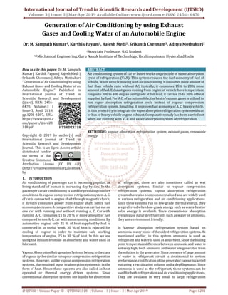
![International Journal of Trend in Scientific Research and Development (IJTSRD) @ www.ijtsrd.com eISSN: 2456-6470
@ IJTSRD | Unique Paper ID – IJTSRD23318 | Volume – 3 | Issue – 3 | Mar-Apr 2019 Page: 1202
capacities in applications ranging from domestic
refrigerators to large cold storages. Since ammonia is not
compatible with materials such as copper or brass,normally
the entire system is fabricated out of steel.
A. Basic Working Principle of Vapour Absorption
Refrigeration System
A Simple Vapor absorption system consists of evaporator,
absorber, generator, condenser, expansion valve, pump &
reducing valve. In thissystemammoniaisused asrefrigerant
and solution is used is aqua ammonia. Strong solution of
aqua ammonia contains as much as ammonia as it can and
weak solution contains less ammonia. The compressor of
vapor compressor system is replaced by an absorber,
generator, reducing valve and pump.
Fig.1: Basic Principle of Vapour Absorption Refrigeration
System [2]
The heat flow in the system at generator, and work is
supplied to pump. Ammonia vapors coming out of
evaporator are drawn in absorber. The weak solution
containing very little ammonia is spread in absorber. The
weak solution absorbs ammonia and gets converted into
strong solution. This strong solution from absorber is
pumped into generator. The addition of heat liberates
ammonia vapor and solution gets converted into weak
solution. The released vapor is passed to condenser and
weak solution to absorber through a reducing valve. Thus,
the function of a compressor is done by absorber, a
generator, pump and reducing valve. The simple vapor
compressor system is where there is scarcity of electricity
and it is very useful at partial and full load.
2. LITERATURE REVIEW
Absorption refrigeration was discovered by Nairn in 1777,
though the first commercial refrigerator was only built and
patented in 1823 by Ferdinand Carré, who also got several
patents between 1859 and 1862 from introduction of a
machine operating on ammonia– water. The absorption
refrigeration system went through upsanddowns, beingthe
antecessor of the vapour compression refrigeration system
in the 19th century. By that time systems operating on
ammonia water found wide application in residential and
industrial refrigerators. Systems operating on lithium
bromide–water were commercialized in the 1940’s and
1950’s as water chillers for large buildings air conditioning.
Perez-Blanco- Substitution of petroleum-based combustion
fuels in the 1970’s affected the application of absorption
refrigeration, but, at the same time,newopportunitiesarose,
such as usage of solar energy to operate this system energy
costs and other factors has contributed to frequent use of
low temperature energy waste from chemical and
commercial industries to operate absorption refrigeration
systems.[1]
Low pressure refrigerant vapour leaves the evaporator and
enters the absorber. Here the formation of “solution pair”
takes place i.e. combination ofrefrigerantandabsorbentand
the formed solution is strong in nature. Now this strong
solution is then pumped to the generator and here the
pressure increases. In generator this strong solution is
heated by some external source which in this case study is
“solar energy”. After the heating process is accomplished
strong solution at high pressure moves to the condenser
leaving back the weak solution which is send back to the
absorber using an expansion valve. Now the high-pressure
refrigerant moves from generator to the condenser where
the refrigerant vapour is condensed to high pressure liquid
refrigerant. This liquid refrigerantispassedtothe expansion
valve and where it is forwarded to theevaporator,wherethe
refrigeration effect is achieved and thus completes the
complete vapour absorption cycle. [2]
The working fluid in an absorption refrigeration system is a
binary solution consisting of refrigerantand absorbent. Two
evacuated vessels are connected to each other. The left
vessel contains liquid refrigerant while the right vessel
contains a binary solution of absorbent or refrigerant. The
solution in the right vessel will absorb refrigerant vapor
from the left vessel causing pressure to reduce. While the
refrigerant vapor is being absorbed, the temperature of the
remaining refrigerant will reduce as a result of its
vaporization. This causes a refrigeration effect to occur
inside the left vessel. At the same time, solution inside the
right vessel becomes more dilute because of the higher
content of refrigerant absorbed.
This is called the “absorption process”. Normally, the
absorption process is an exothermic process, therefore, it
must reject heat out to the surrounding in order to maintain
its absorption capability. Whenever the solution cannot
continue with the absorption process because of saturation
of the refrigerant, therefrigerantmustbeseparatedoutfrom
the diluted solution. Heat is normally the key for this
separation process. It is applied to the right vessel in order
to dry the refrigerant from the solution. The refrigerant
vapor will be condensed by transferring heat to the
surroundings. With these processes, the refrigeration effect
can be produced by using heat energy. However, the cooling
effect cannot be produced continuously as the process
cannot be done simultaneously. Therefore, an absorption
refrigeration cycle is a combination. [3]
The aim is to develop a system using silencer for rural
electrification. The system controls the whole setup. Air
blowers the generally use centrifugal force to propel air
forward. Inside a centrifugal air blower is wheel with small
blades on the circumference and acasingtodirecttheflowof
air into the centre of the wheel and out toward the edge. The
design of the blade will affect how the air is propelled and
how efficient the air blower is. The project makes use of a
Silencer setup, turbine and DC Generator. The energy
obtained is stored to a battery. The battery supply is fed to
pulse generator and in turn to a MOSFET which is capable of
generating ON/OFF pulses of different frequency. This isfed
to a step-up transformer to generate a low voltage AC. This
AC is fed to electrical appliance. The study “Power
Generation Using ExhaustGases”canbedoneusingMOSFET,
Mono stable multi vibration, DC motor we can generate
voltage with inverter using energy through silencer The](data:image/gif;base64,R0lGODlhAQABAIAAAAAAAP///yH5BAEAAAAALAAAAAABAAEAAAIBRAA7)