Downloaded 72 times


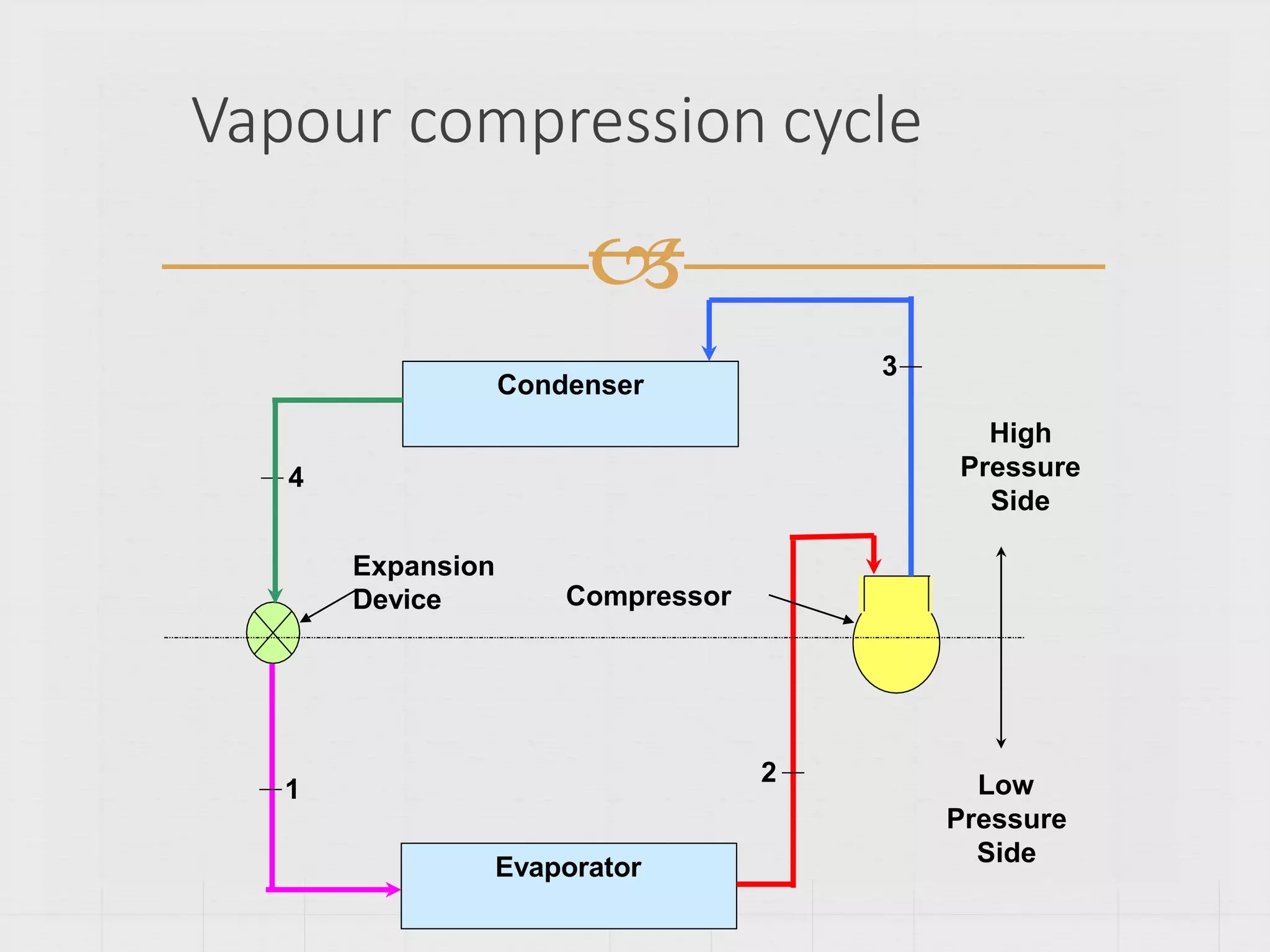


Refrigerators and heat pumps transfer heat from a low-temperature medium to a high-temperature medium. They differ only in their objectives - refrigerators remove heat (cooling), while heat pumps supply heat. The vapor-compression cycle is the most common refrigeration cycle. It involves four main components: evaporator, compressor, condenser, and expansion valve. Heat is absorbed in the evaporator and rejected in the condenser. The compressor raises the refrigerant pressure and temperature between these components. The performance of vapor-compression refrigeration systems depends on factors like evaporator/condenser temperatures and pressures. Actual cycles are less efficient than ideal cycles due to irreversibilities like heat transfer across a temperature
Defines refrigeration and introduces the concept of refrigerators and heat pumps.
Explains the function of refrigerators (QL) and heat pumps (QH) and their operational differences.
Describes the refrigeration cycle, highlighting the heat transfer processes and work involved according to thermodynamic laws.
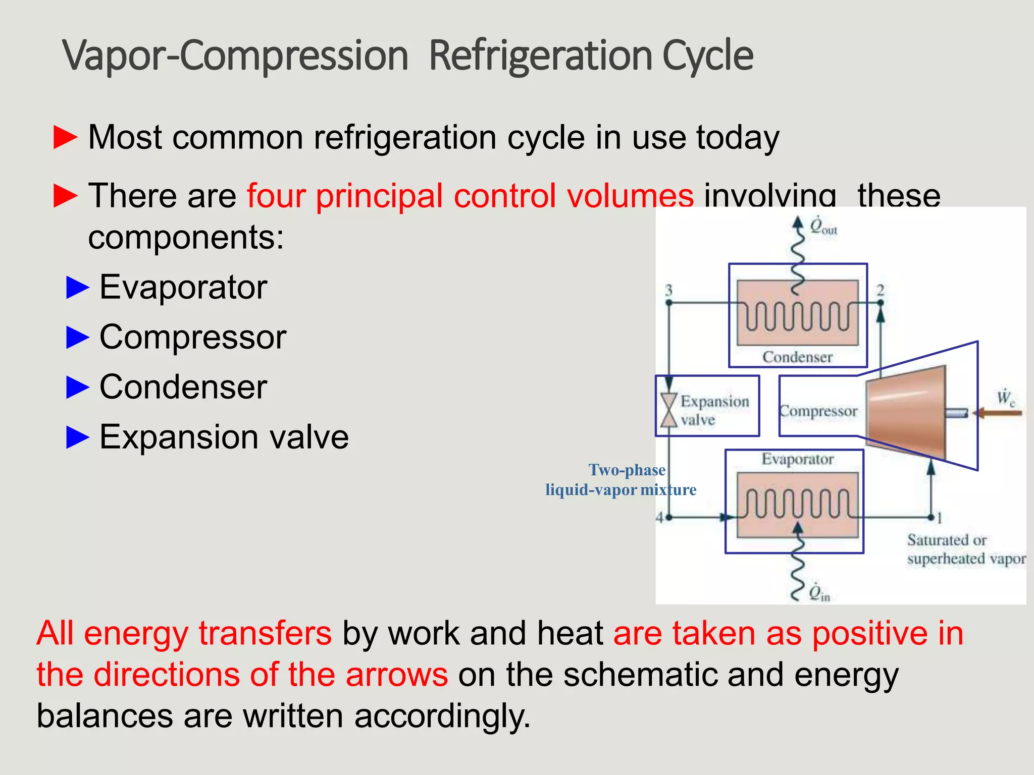
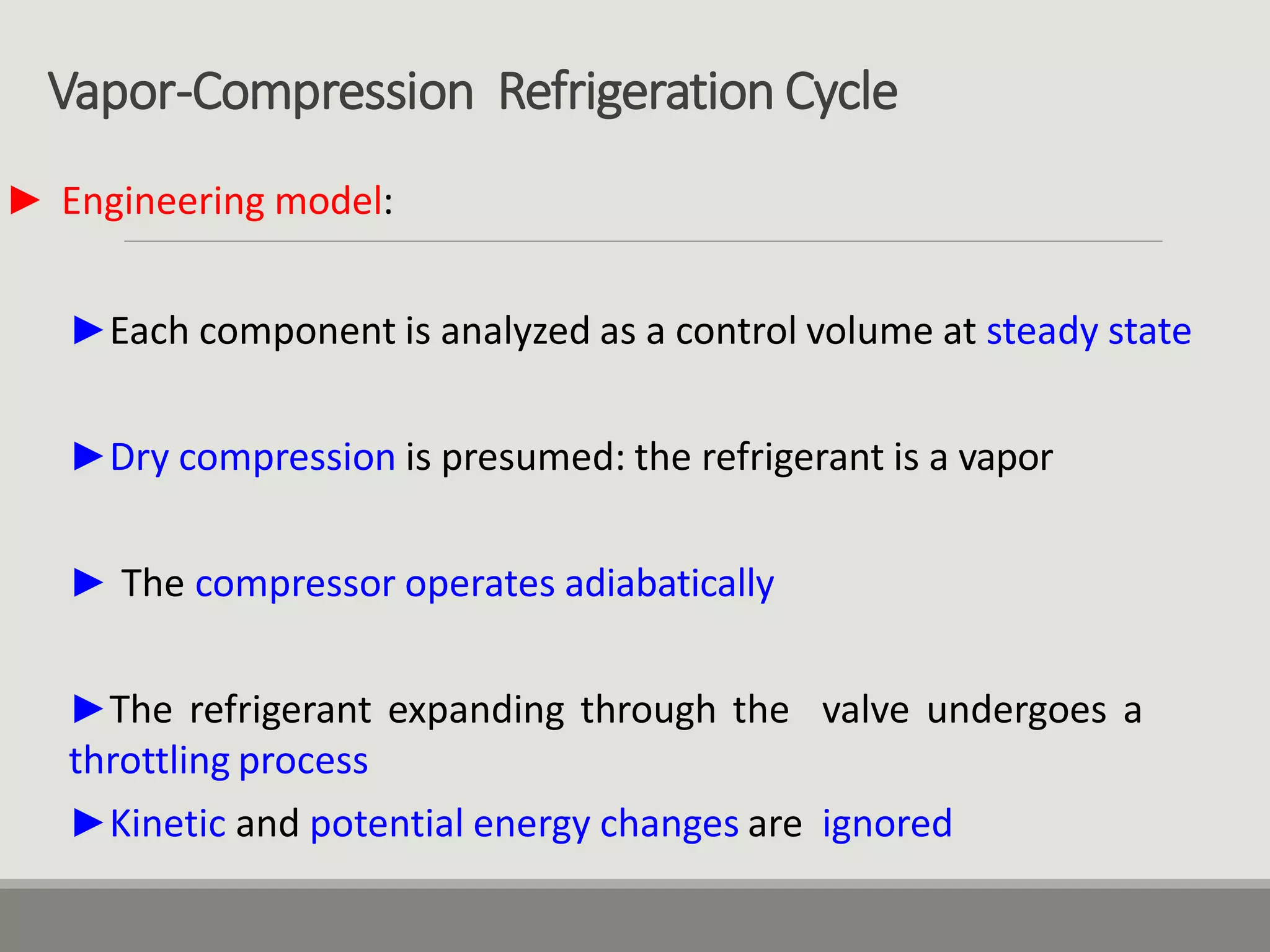
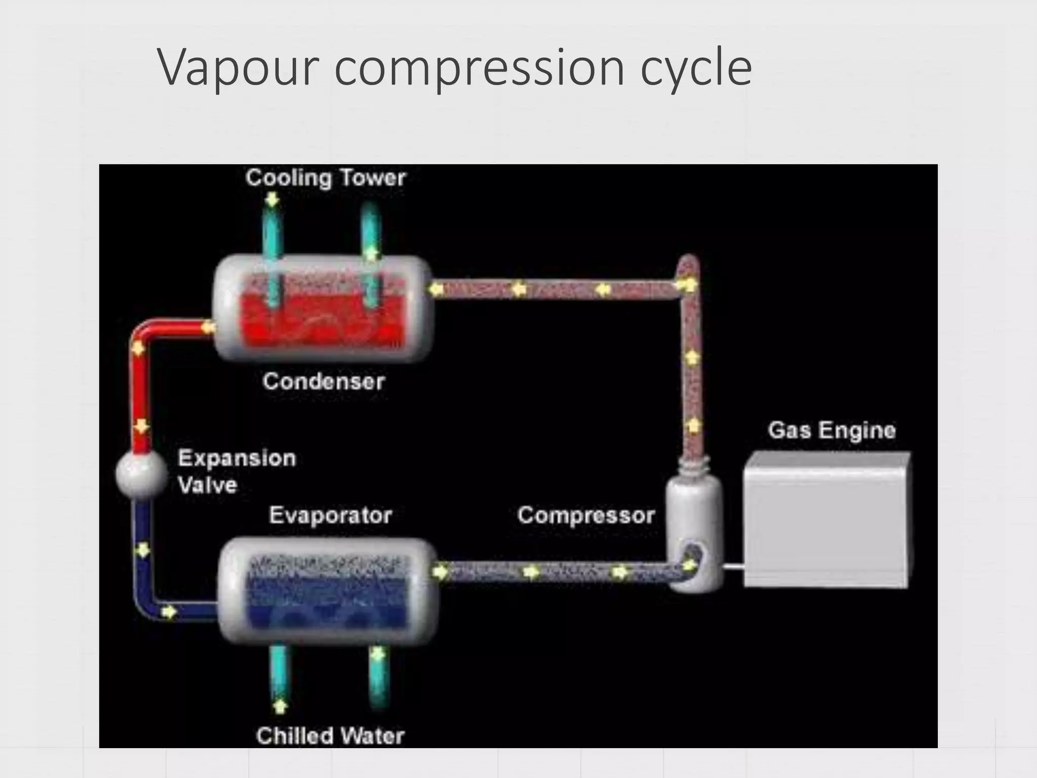
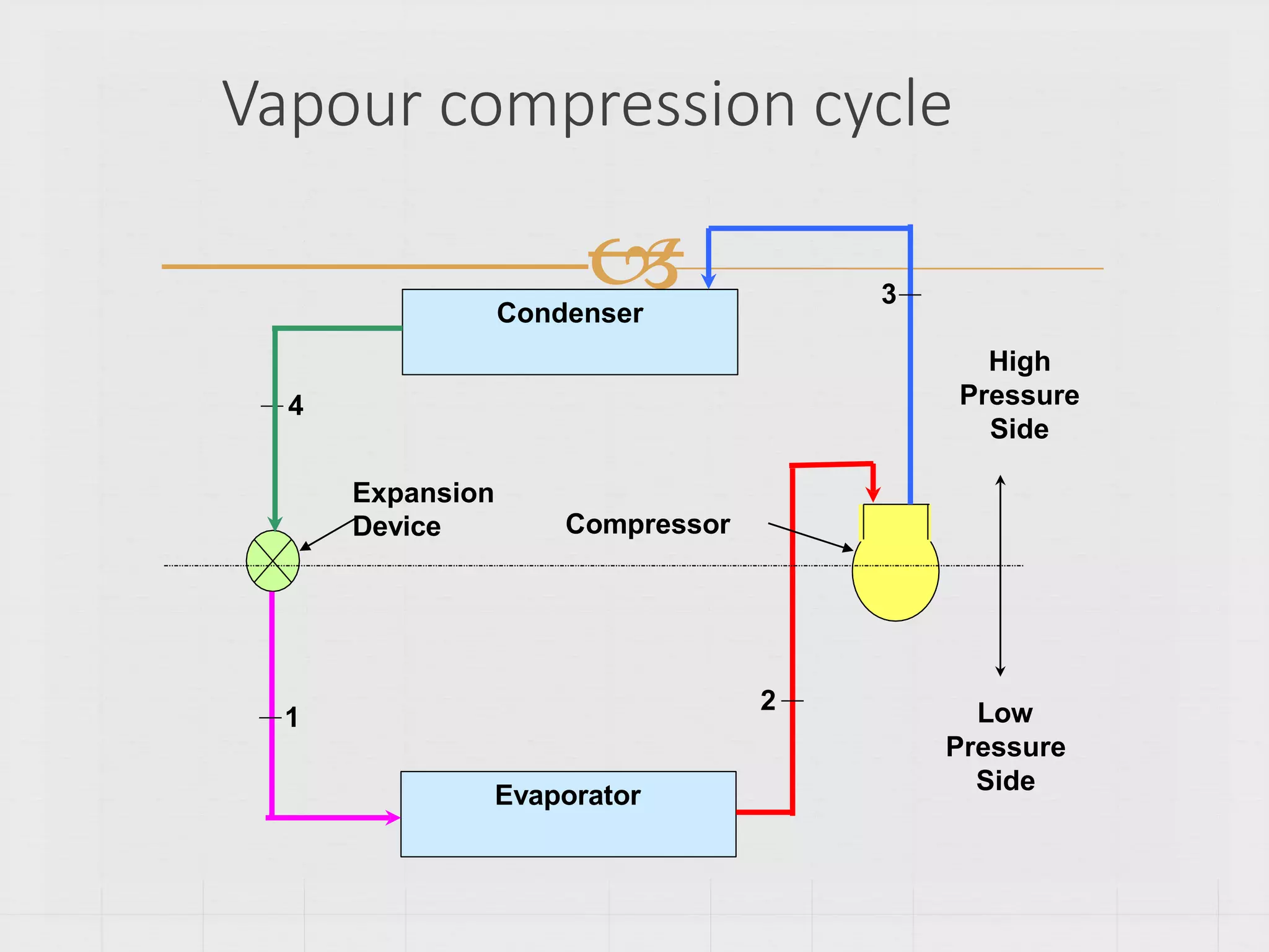
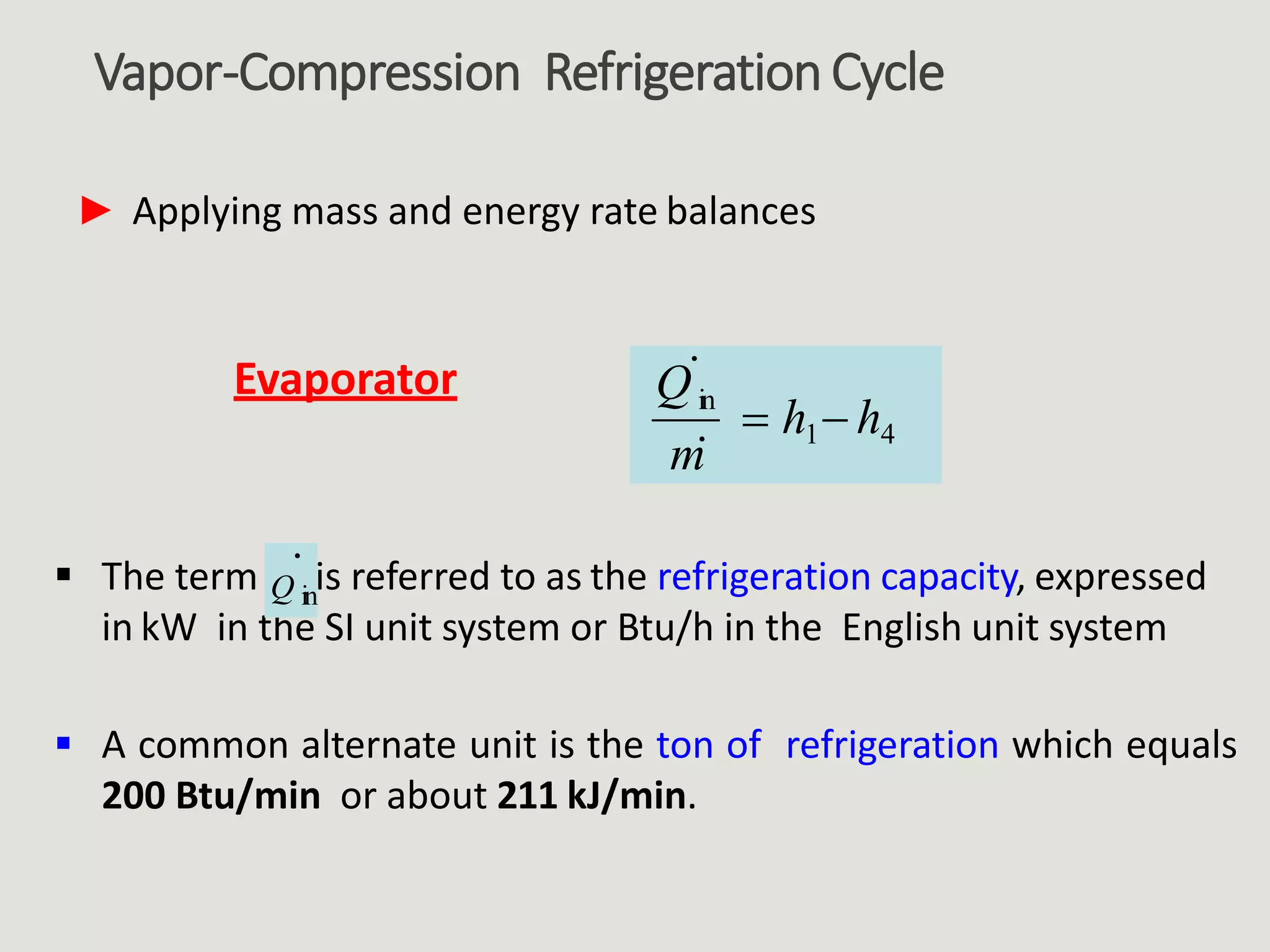
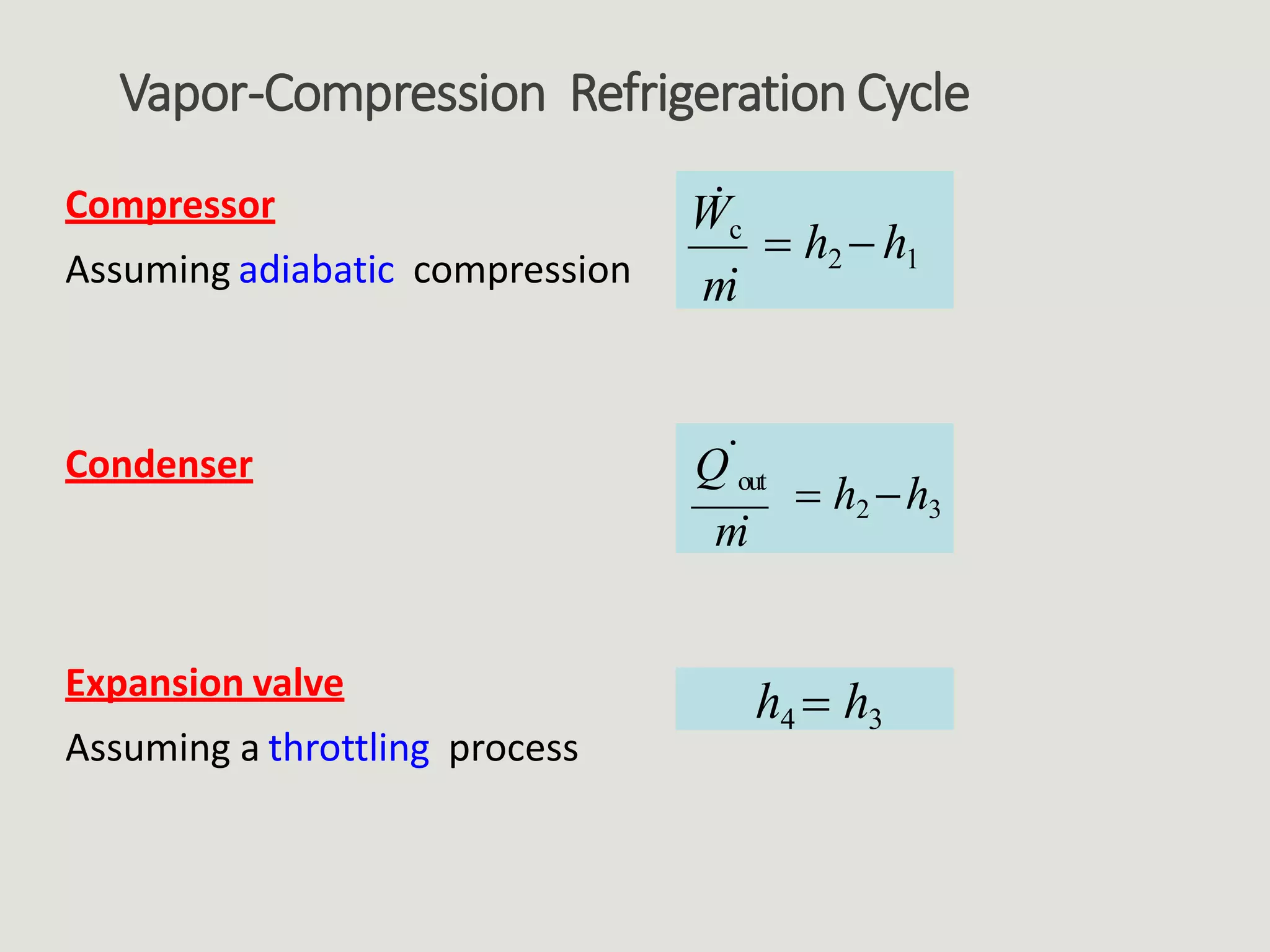
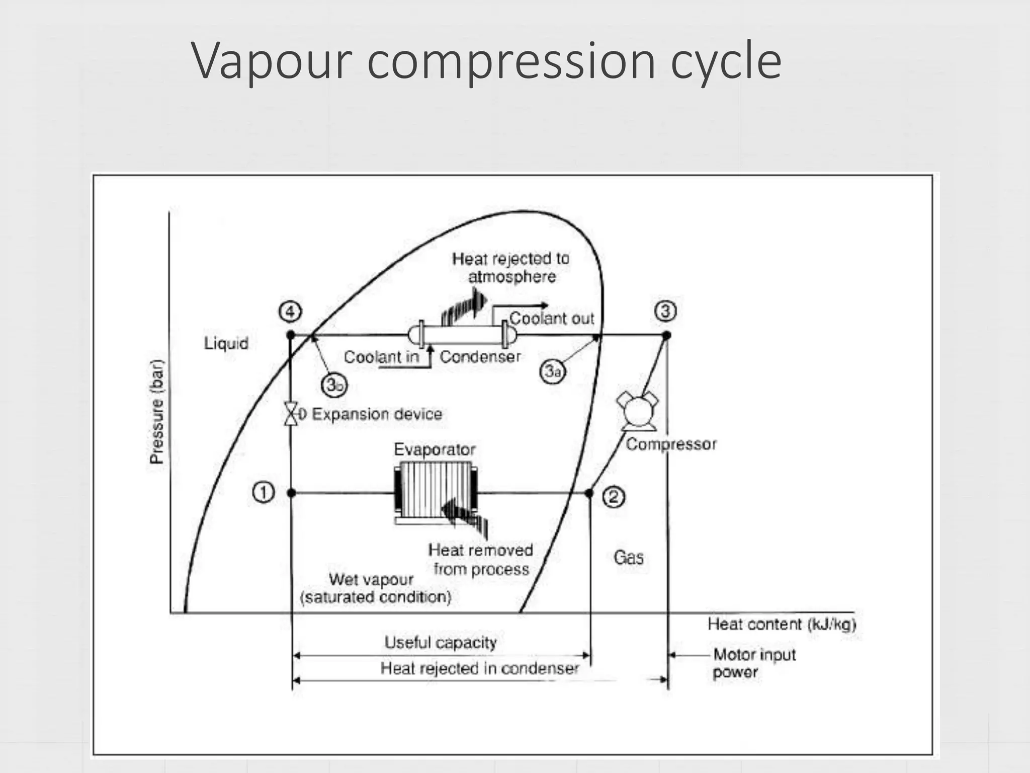
Details the vapor-compression refrigeration cycle, including core components like evaporator, compressor, condenser, and expansion valve.
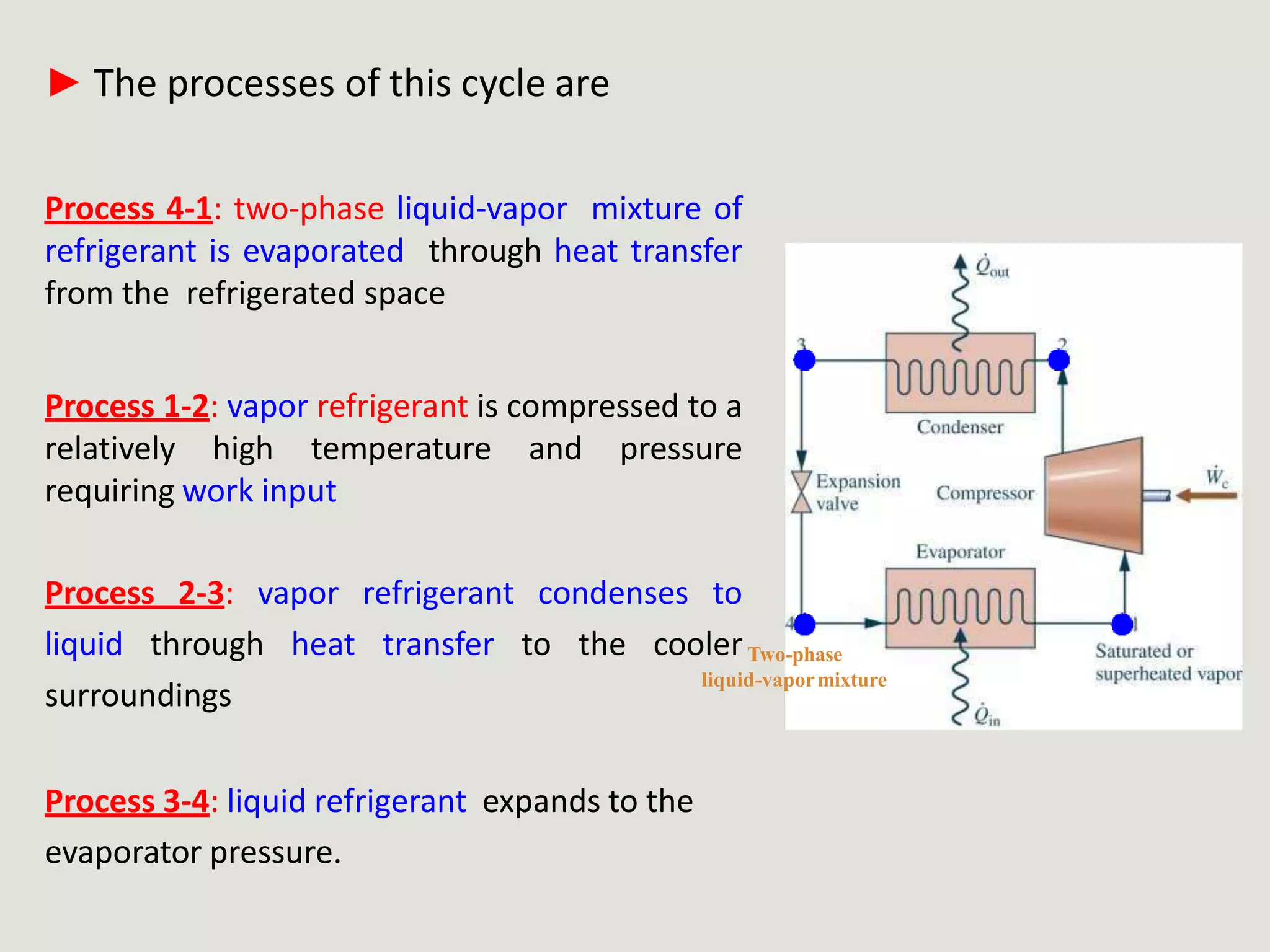
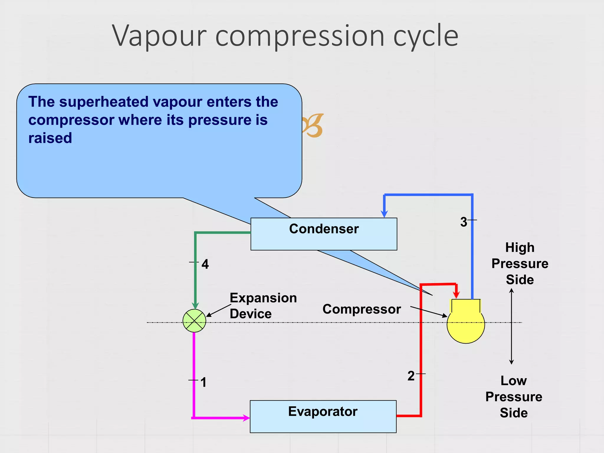
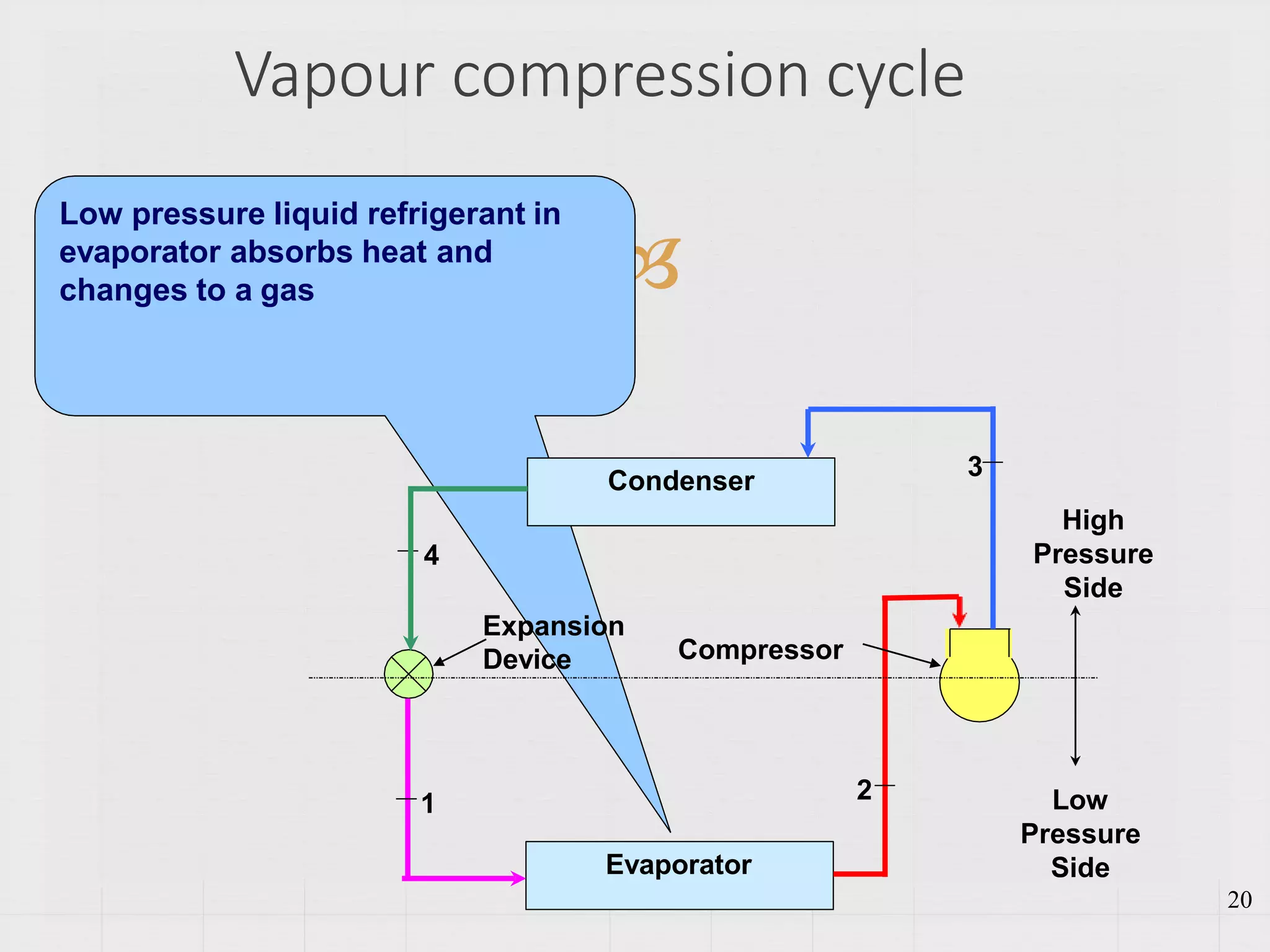
Elaborates on each process within the vapor-compression cycle and introduces refrigeration capacity metrics.
Discusses performance parameters, including work and coefficients of performance (COP) for refrigeration cycles.
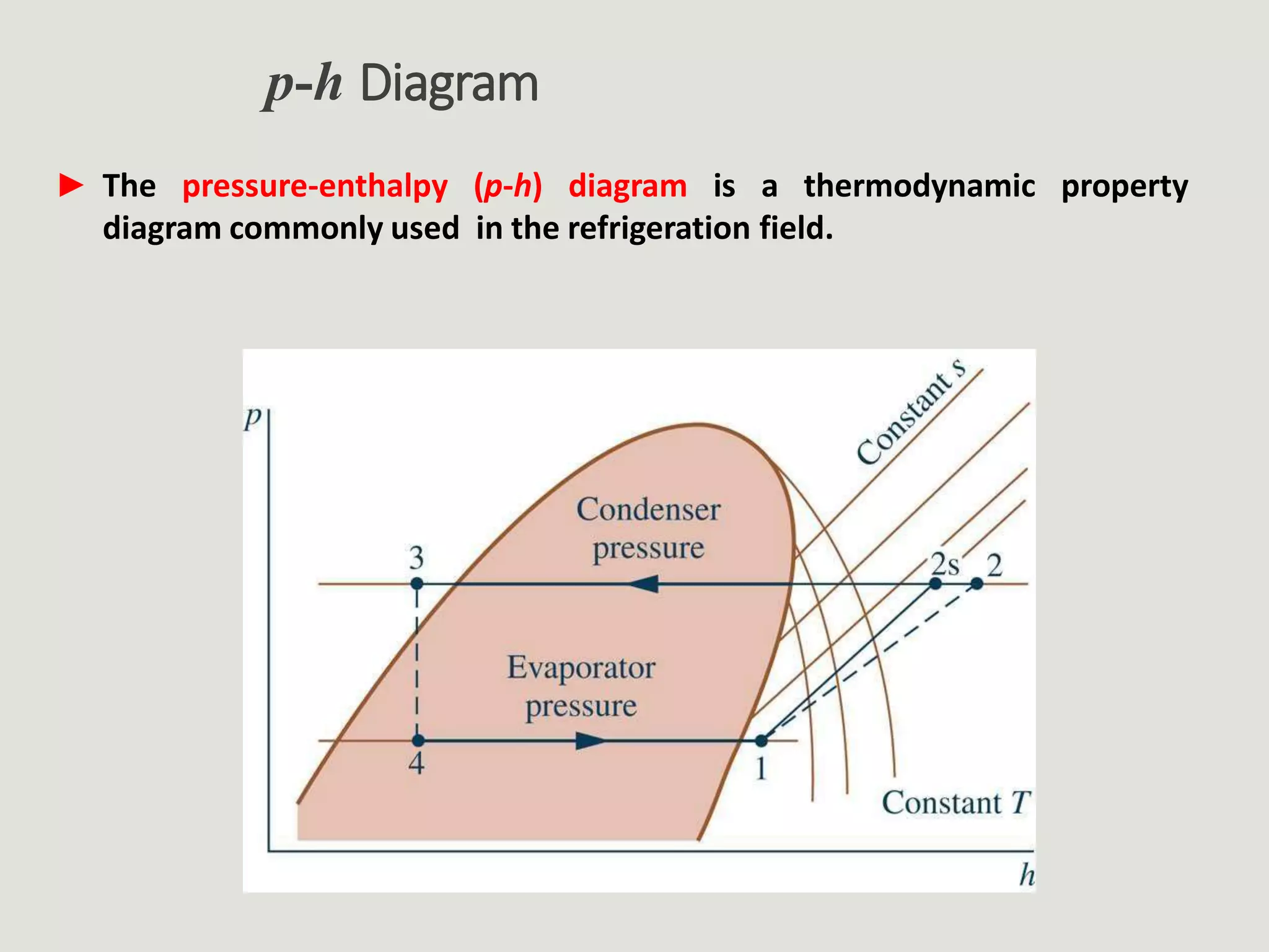
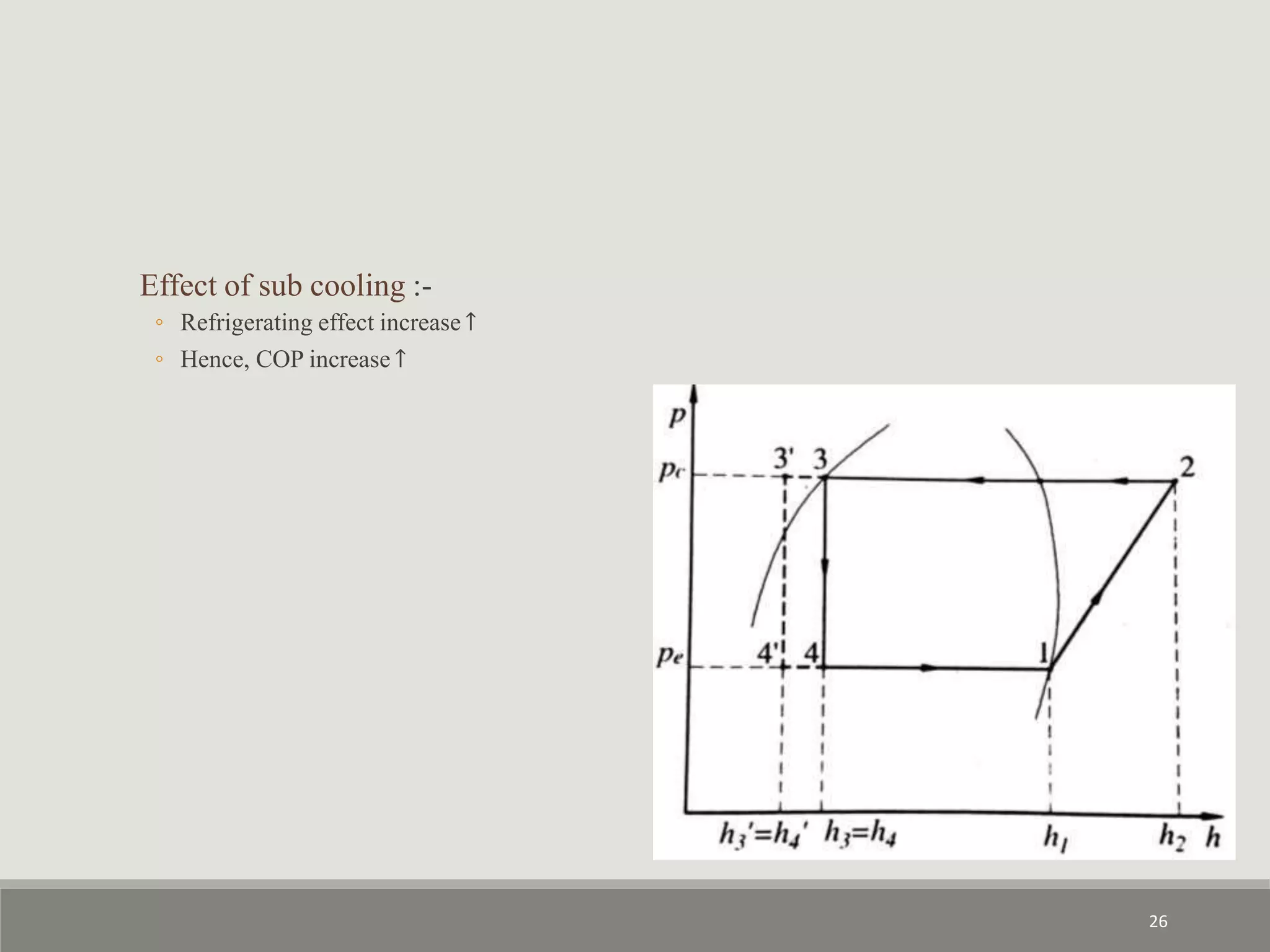
Introduces the p-h diagram, a key thermodynamic tool for understanding refrigeration processes.
Explains different outputs of the compressor, including the states of vapor and their effect on cycle efficiency.
Examines various factors impacting COP in vapor-compression refrigeration systems such as pressure and temperature variations.
Discusses criteria for refrigerant selection, environmental considerations, and types of refrigerants including CFCs and natural options.
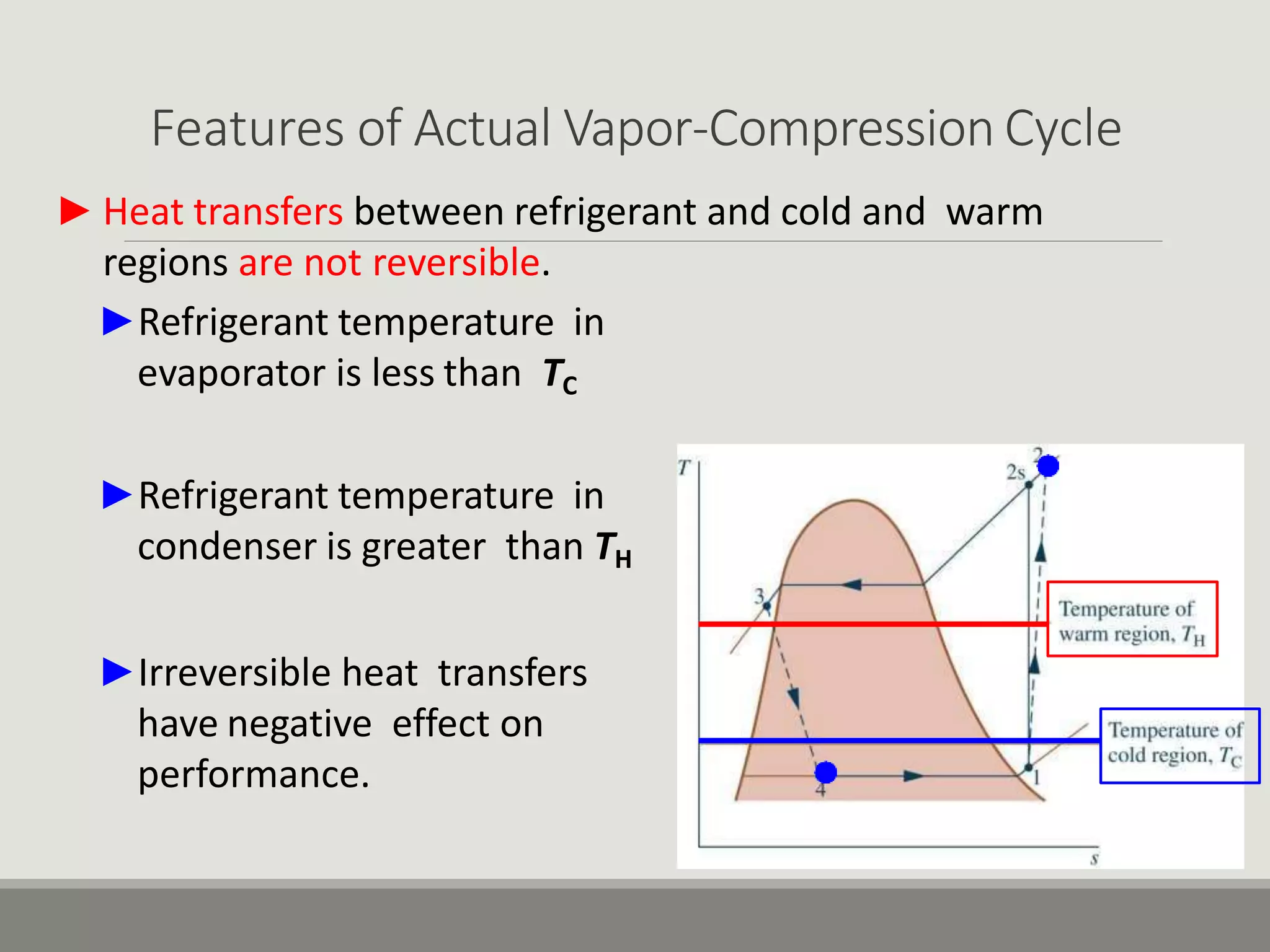
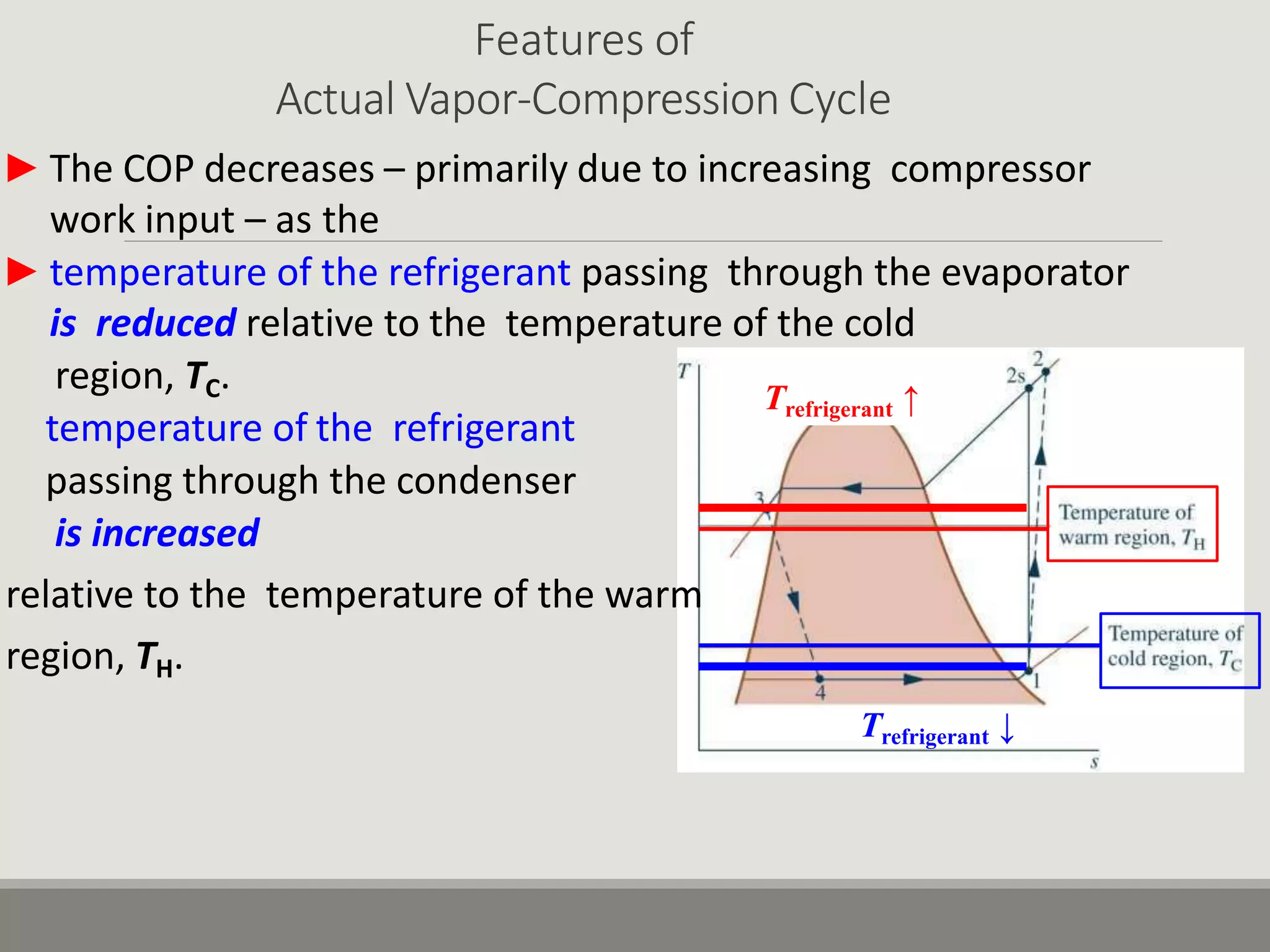
Explains irreversibilities in the actual cycle, effects on COP, and introduces isentropic compressor efficiency.


