1. THE ABSORPTION SYSTEM
tain domestic applications have moving this was accomplished he extinguished
parts reduced to a minimum. the flame under the powder and pro-
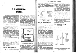
Chapter 13 Fig. 13-2 illustrates a simple ah- ceeded to observe the characteristics
sorption system of the liquidabsorbent of the newly discovered substance.
A few moments after the flame had
THE ABSORPTION
been extinguished, Faraday began to
note a most unusual occurrence. The
liquid ammonia, instead of remaining
SYSTEM
quietly in the sealed test tube, beganto
t bubble and then to boil violently. Itwas
rapidly changing back into a vapor, and
the vapor was being reabsorbed by the
powder. Upon touching the end of the
The absorption system differsfrom so tube containing the boilingliquid, Fara-
the compression system in that it uses th day was astonished to find it intensely
heat energy instead of mechanical en- duced for the purpose of compariso cold. Ammonia, in changingfromliquid
ergy to make a change in the condi- with mechanical types of refrigerators
tions necessary to complete a refrig- The condensing coil, receiver, an
13.2. Elementary liquid absorbent cycle. A. Generator: form' extracted heat andit took
6. condenier: C. ueceiver; D. cooiing coil; E. Burner: this heat from thenearestthingathand,
eration cycle. This system uses gas. c F. water-in: G. w a t e r - ~ ~ t . which was the test tube itself.
kerosene, or an electric heating ele- u The diagram inFig. 13-3illustrates
ment a s a source of heat supply. 13-3. THE SOLID ABSORPTION the Faraday experiment.
13-1. TYPES OF ABSORPTION system does not work so simply 13-4. ABSORPTION SYSTEM
SYSTEMS the illustration portrays, but functio Michael Faraday, in 1824,perform- CHEMICALS
ed a series of experiments to liquefy
There are several usable combina- certain "fixed" gases -- gases which Several different chemical com-
tions of chemicals that have the prop- certain scientists believed could exist binations have heen used in absorption
erty that one may absorb the other with- only in vapor form. Among them was units,
out any chemical action taking place. ammonia, for it had always been re- Ammonia a s the refrigerant and
The 'substance bas the property to ab- garded a s a "fixed" gas. Faradayknew
sorb the other chemical when cool, but that silver chloride, a white powder,
will release the chemical when heated. had the peculiar property of absorbing
If the substance is a solid, the process large quantities of ammonia gas. He
i s sometimes called adsorbing while if therefore exposed silver chloride to
CHILLING
the substance i s a liquid, the process dry ammonia gas. When the powderhad ABIORBER
is called absorbing. absorbed all of the gas it would take.
There are two principal types of he sealed the ammonia-silver chloride
absorption refrigerators: one utilizing compound in a test tube which was bent
a solid absorbent material, the other to form an inverted "V." He then *
......
..
...
.
....
...
.
..:. 'P,
using a liquid absorbent. The liquid ab- ted the end of the tube containing :....
4 sorbent machine i s the most popular. powder and at the same time cooled - -
t -
These two types of absorption re- opposite end of the tube with water.
A
-
frigerators are typified by the Fara-
day, which is a solid absorbent type 13-1. Elementary solid absorbent cycle.
and by the Electrolux, which uses a
liquid absorbent. by leaving out the various cont
that are explained in detail later.
CONOENSER
13-2. THE ABSORPTION SYSTEM The most appealing feature of araday continued the heating pro-
system is the elimination of m ess until sufficientliquidammoniahad 13-3. Elementary operation of the interrniitent abiorp-
een produced for his purpose. When tion cycle.
Fig. 13-1 illustrates a simple ah-r parts down to a few valves, while (Faraday Reirigerator Carp.)
316 317
2. MODERN REFRIGERATION, AIR CONDITIONING
water as the absorbent is the most paratus is so constructedthat it canob-
: popular. tain this ammonia only fromthe cooling
. High temperature units (air condi- unit, which necessitates anevaporation
iioning) a r e now using water as the re- taking place there. From elementary
frigerant and lithium bromide o r lithi- physics one knows that this will cause
urn chloride as the absorbent. Thepres- the removal of beat from the cooling
sure in these systems varies between 15 unit and its surroundings, and if this
psia in the cooling coil to 1psia in the cooling unit is located in an insulated
condenser. box (a refrigerator box) that box will
One company is using methylene be refrigerated'
chloride a s the refrigerant and di- AS the ammonia
methyl ether of tetraethylene the cooling unit it is replaced by liquid
a s the absorbent. The pressures are ammonia from the receiver. This oper-
3psig and 24 in Hg. vacuum. ation continues until the properamount
of ammonia is reahsorhed by the gen-
erator, when heat is again applied and
13-5. TYPICAL SOLID ABSORBENT ammonia is again moved to the re-
SYSTEM
ceiver.
From the description it is seenth
Froan Fig. 13-1 the followingelem- the cycle.
is intermittent and that the
entary cycle =Y he traced. Heat i s ap- complete
cycleembraces both a gen-
plied the generator Or
erating period and anabsorbingperiod. FOOD SPACE
which will liberate ammonia gas from This cycle may be easily traced from
its absorbent and will increase the Fig. 13-2,
pressure to the point where the air or This in principle is the Faraday re-
water cooled condenser will remove frigerator and its cycleis explained
sufficient heat from the high pressure in detail in Chapter 14,
RECTIFIER
gaseous ammonia to reduce it to a
liquid.
The liquid refrigerant is forced 13-6. TYPICAL LIQUID
from the condenser to the receiver or ABSORBENT SYSTEM
storage tank by the pressure of the
vipor entering the condenser. The liquid absorbent system seems
After sufficient ammonia is driven to possess some very desirable char-
into the condenser and receiver, the acteristics. Water at ordinary pres-
heat i s discontinued and the generator sures and temperatures will absorb
o r absorber cools. When the tempera- great quantities of ammonia. Ammonia
lure of the absorber is lowered suffi- absorbed in water may be easily driven
ciently, it hegins taking back or re- from the water by the addition of heat.
absorbing the ammonia gas. As theah- Also liquid ammonia has a high latent
sorber cools it attracts the gas am- heat of vaporization.
monia molecules and a s they enter the The Serve1 is a domestic ~ f r i g e r -
ahsorber and are changed to a liquid atqr which is designed to operate in a AMMONR HYOROGLN SOLUTION
two things happen. First, the absorber continuous cycle and has no moving
heats up and this heat must he removed. parts or valves other than to control I
+ C )
Second, the pressure in the container the burner flame. The refrigerant is
is reduced to the level where theliquid ammonia with water used a s the ab-
ammonia can convert again to a gas at sorbent; hydrogen gas is utilized to 13-4. Diagram of the Servel absorption cycle I, la, l b generator, 2, 2a. Zb, condenser, 3. 3a, 3b. cooling
coil,
such a low heat level that refrigerating create a partial pressure (Dalton's 4 absorber, 5 hydrogen reserve vessel, 6 analper. 7 rectifier, 8 gas heat exchanger. 9 liquid heat exchanger, 10
temperatures are produced. The ap- Law, Paragraph 1-18) to allow th percolator tube, separator, I 2 precooler.
(Copyright 1955 by Servel lnc.)
3. MODERN REFRIGERATION, AIR CONDITIONING
ammonia to evaporate at a low pres-
sure.
In Fig. 13-4, A represents am-
monia, and H is hydrogen.
When the burner i s lighted and its
heat applied through the center of the
generator, ammonia vapor is released
from the solution. This hot vapor in
part (Ib) passes upward through the
percolator tube (lo), and as the hot
ammonia vapor rises through this tuhe
it carries the solution to the upper
level of the separator (11).
Most of the liquid solution settles
in the bottom of (11) and flows through
the liquid heat exchanger (9) into the
absorber (4). The hot ammonia vapor
being light rises to the top of (1l)tube.
The hot ammonia vapor then passes
downward through the center tuhe, into
the analyzer (6). Here any water vapor
is removed while the hot ammoniavapor
rises into the rectifier (7).
The rectifier consists of a series
of small baffle plates, surrounding the
tube. If the hot ammonia vaporstillhas
some traces of water vapor, it mustbe
removed toinsure pure ammoniavapor.
The heat has at this point com-
pleted its work. For the remainder of
the cycle, the natural force of gravity
is depended upon to create circulation.
The pure hot ammonia vapor con-
tinues into the condenser (2).
The air, passing through the fins
takes out the heat from the ammonia
vapor, thus condensing some of the
vapor in liquid in (2a). This ammonia
is now in a pure state, and it flows
into the evaporator (3d).
The ammonia gas that does not con-
dense in (2b) where the rest is con-.
densed drains to the upper tube o r
trap.
The U-tube is the receiving and
storage compartment inthe cycle where
the liquid ammonia i s allowed to build
up to a predetermined level; then it
flows into the cooling coil (3a).Because
a liquid will always seek its own level,
the liquid ammonia flows by gravity
through the liquid ammonia tube and
spills into the cooling unit.
As the liquid ammonia falls intothe
cooling unit, (3a and 3h) it forms in
large shallow pools on a series of
horizontal baffle plates. The hydrogen
that is being fed t o the cooling unit
permits the liquid ammonia to evap-
orate, (Dalton's principle) at a low
temperature. During this process of
evaporation, the ammonia absorbs heat
from the food compartment of the re-
frigerator and causes the water in the
ice-cube containers to freeze. The
more hydrogen and less ammonia the
lower the temperature. The evaporator
vapor formed by the evaporating of the
liquid ammonia, mixes with the hydro-
gen. This mixture is heavier than hy-
drogen alone and moves downward
through the middle of the gas head ex-
changer (8) into the absorber (4). This
circulation is continuous in the cooling
unit. The mixed gases that pass through
the gas heat exchanger cool the hy-
drogen rising in the outer tuhe.
During this time a weak solution o
f
ammonia and water is flowing fromthe
generator (11) to the top of the absorber
(4) by way of the liquid heat exchanger
(9). Here it meets the mixture of hydro-
gen and ammoniavapor comingfrom the
evaporator by way of the gas heat ex-
changer. The weak solution absorbs the
ammonia vapor. The hydrogen is left
free; since hydrogen is insoluble in
w-ater and is very light, it now rises to
the top of the absorber and returns to
the cooling unit by way of the gas heat
exchanger (8).
The absorber (4) has fins and is air
cooled. The cooling of the weak solution
helps it to absorb the ammonia gas out
of the mixture of ammonia and hydro-
gen. Also when the weak watersolution
absorbs the ammonia gas, considerable
heat is liberated and the aircooledfins
ml~st
remove this heat to permit refrig-
eration to continue.
THE ABSORPTION SYSTEM
The solution, now a strong solution A more detailed study is made of the
f ammonia and water, drops tothebot- Servel in Chapter 14.
om of the absorber 14) and continues
. .
,
2
,
$ down through the liquid heat exchanger 13-7. KEROSENE BURNING
,$$
I,$),& (9). REFRIGERATORS
A very convenient refrigerator cy-
cle for localities not furnished with
gas or electricity is the Superfex and
Trukold cycle. The Superfex cycle is
basically the Faraday priqciple but
incorporates features which warrant
a description.
Ammonia is mixed with water in a
tank or generator (A) under which are
located some kerosene burners (M).
The burners are lighted and the heat
produced drives the ammonia in vapor
form out of the mixture. This am-
monia vapor is forced up a pipe (D)
and through a coil (E) which is im-
mersed in water contained in a tank
1B) on too of the refricerator (note
.. . , -
L armvs Fig. 13-5). 'The lower ttm-
~ ~ F P ~ ~ u P E
C J ~ ~ S U S
the anmonin vaDor to
13-5. The generation or heating inteivai in a typical
;,termittent vpe
absorption refrigeratar.
(Perfection Stove Co..Inc.]
The liquid heat exchanger carries
the strong liquid, o r refrigerant, back
to the analyzer (6) and to the generator
it again starts its cycle.
The rectifier (7) insures that any
vapor still in the ammonia will
condense and drainbackto the analyzer.
The a ~ ~ a r a t u s
is a welded assemblv.
..
There are no moving parts to wear out
and go out of adjustment. The totalpres-
sure throughout the cycle is about 200
psig, necessitating a rugged construc-
tion which insures a long life.
To produce a 0 F refrigerant in the
cooling coil the ammonia must boil at
15.7 psig, which means that the hydro-
gen must make up the remainder of the
pressure (184.3 psig). This refrigera-
or i s consideredto be unique among the
domestic ones sold intbe United States.
change back to a liquid at the high
generating pressure. This liquid am-
monia drops through a pipe into the
liquid receiver (C) and from here it
passes to the cooling unit (K) which
is surrounded by a brine (H). The li-
quid receiver is insulated (F) to pre-
vent this container from overcooling
the food compartment by acting as the
cooling coil. This process continues for
a relatively short time until all the
kerosene is consumed and the burners
automatically go out. As the absorber
cools to room temperature, the am-
monia will evaporate at a very low
temperature in the cooling unit be-
cause a s the generator cools it tends
to re-absorb the ammonia gas, there-
by reducing the pressure and permit-
ting the liquid ammonia in the eva-
porator to boil at low temperatures.
This evaporation causes the cooling
effect on the contents of the food com-
partment which is called refrigera-
tion.
4. MODERN REFRIGERATION, AIR CONDITIONING
In detail, the water in the genera- oil burners drives the ammonia from
tor (A) cools very quickly after the the generator (A) to the cooling unit
burners have gone out, and as cool (K) in a short time; the ammonia in
water bas a strong affinity for am- the cooling unit vaporizes and passes
monia, the ammonia vaporized in the hack to the generator slowly w e r a
period of twenty-four to thirty-six
13.6. The period in an intermittent type ab-
~orption
refrigerator.
[Pedectian Stove Co., Inc.]
cooling unit passes back (note arrows
Fig. 13-6) to the generator through a
connecting pipe (G)
and is re-absorbed
by the water in the generator main-
taining a low evaporating pressure in
the cooling unit.
In other words, the heat from the
hours. The vaporization of the am-
monia in the cooling unit produces the
refrigerating effect.
For additional efficiency in unusu-
ally hot climates or for handling ex-
tra large loads, a depression (L) in
the top of the condenser tank may be
filled with water which will evaporate
rapidly and aid the cooling of the tank.
This refrigerator is also explained
in Chapter 14 along with the Trukold
and Icy-ball which are fundamentally
similar to it.
Without exception the absorption
mechanisms are provided with a fuse
plug which will release the charge
from the mechanism when the tem-
perature of the unit becomes excess-
ive 175-200 F. This device prevents
any possibility of the complete mech-
. .
anism exploding.
An absorption refrigerator using
sulphur dioxide a s the refrigerant was
produced a few years ago but did not
continue on the market. It was of the
intermittent type wing silica-gelas the
absorbent material. The action was
very similar to action in the inter-
mittent types just explained. This ab-
sorption system is used on some rail-
road freight cars.
THE ABSORPTION
REVIEW QUESTIONS
Name the lettered parts of Fig-
ure 13-2. 9.
Why is the ammonia and water
comhination so popular?
What purpose does the hydrogen 10.
serve in the Electrolux?
What localities are especially in 11.
need of the kerosene-fired in-
termittent absorption refrigera-
tors? 12.
Who first discovered the absorp-
tion principle?
Why must the absorberbe cooled 13.
in the Servel cycle?
What is the purpose of a heat
exchanger? 14.
How can burning more gas in
the Servel cycle produce more
SYSTEM
cold?
Why is the storage cylinder o r
receiver in the Superfex refrig-
erator insulated?
Why are these mechanisms pro-
vided with a fuse plug?
Name three substances used in
absorption refrigerators to ab-
sorb the refrigerant gas.
In absorption refrigerators, does
the liquefication of the refriger-
ant depend upon compression?
Does the generator serve any
other purpose in the Superfex?
What?
Have absorption refrigerators
using sulphur dioxide ever been
used?
5. ABSORPTION SYSTEMS, CONSTRUCTION FEATURES
Chapter 14
ABSORPTION SYSTEMS
CONSTRUCTION FEATURES
The refrigeration systems of the These units were operated by a
absorption type have entirely different kerosene heater which when lighted
construction features and service aper- heated the generator for approximate-
ations than the compression cycle sys-
tems. In Chapter 13 the absorption
cycles are explained in detail. It is the
endeavor of this chapter to bring out
the construction features of these re-
frigerators.
14-1. DOMESTIC ABSORPTION
SYSTEMS
Absorption system domestic refrig-
erators have been marketed since the
20's. These units have several advan-
tages. They have no moving parts and
therefore are virtually noiseless. Some
do not require electricity and can pro-
vide refrigeration where electricity is
not available.
There are two types of absorption
machines; the intermittent type andthe
continuous type. The intermittent type
however has practically ceased to ex-
ist. The continuous type is becoming
increasingly popular.
14-2. INTERMITTENT TYPE
ABSORPTION SYSTEMS
The intermittent absorptionmachine
was very popular in the 30's. The
Crosley Corp. manufactured the Icy-
Ball, the Superfex was made by the
Perfection Stove Co. and the T d o l d
was sold by Montgomery Ward.
-
ly one hour. After the burner used up
its fuel and ceased to burn, the re-
frigerator would provide excellent re-
frigeration for about twenty-three (23)
hours. Therefore, the housewife only
needed to fill and light the special
kerosene units once each day.
14-3. SUPERFEX
The Superfex refrigerator was de-
signed to produce good refrigeration
using kerosene a s the source of ener-
gy. The system had the generator on
the left side of the cabinet with the
kerosene burners mounted on racks
and accessible through a small door
on the lower left side. The condenser
was immersed inatank of water mount-
ed on the top of the cabinet.
The system used ammonia as the
refrigerant and water a s the absor-
bent. Note that the cooling coil Was
surrounded by a cold retainer which
served to keep the refrigerator cold
during the heating portion of the cycle.
The cycle is explained in Chapter
13. With this unit there were two pre-
cautions to be observed: The water-
cooled condenser is immersed in a
non-flowing water tank located in the
top of the box. This water level must
the cabinet behind and above the cool-
ing coil. This location is to preventthe
receiver from acting a s the cooling
coil. The burners are mounted on racks
to make shifting of them very simple.
The water reservoir must be kept
filled to the correct depth at all times.
14-5. ICY-BALL
A refrigerator, called the Icy-Ball,
was made by the Crosley Corp. It was
an insulated box with a top door (chest
SUB
AN%
14-1. The Trukold cycle and burnen.
(Montgomery Ward)
-*:
iF be F p t up to the indicated level, es-
6 pecially just before lighting. Thekero-
& sene burners must be clean, dry, and
in good condition. They must be filled 14-2. he Icy-Ball refrigerator.
to the correct indicated level and must
be in a level position when burning or
will result. No ob-
be placed over the
a s this will restrict the
of the cycle.
14-4. TRUKOLD
Another kerosene-fired absorption
.-refrigerator was distributed by Mont-
gomery Ward. This refrigerator was
intermittent in operation; it used am-
.monia and water a s the refrigerant
and absorbent. A kerosene stove was
located under the box and the heating
flue was behind the box, Fig. 14-1.
Note the location of the liquid am-
monia receiver inside the insulation of
model), and a portable generator and a
cooling unit, Fig. 14-2. It is the ab-
I .
sorption type and operates a s follows:
each refrigerator is provided with a
i
kerosene stove and a water bucket. To
start operating, place the generator
over the lighted stove and the cooling i
I
unit in the bucket filled with coldwater 1
for about 90 minutes. Then place the
cooling unit in the refrigerator box and ~
the generator out in the open air. Re- 1
frigeration will be obtained fpr about
24 to 36 hours, Fig. 14-3. An inkert
in the cooling unit is provided with an
ice-tray to make ice cubes. The unit
weighs 39 pounds. and is inexpensive
to operate. It uses ammonia as the re-
frigerant and water as the absorbent. ~
6. MODERN REFRIGERATION, AIR CONDlTlONlNG
14-6. CONTINUOUS TYPE
ABSORPTION SYSTEMS
The continuous type absorption sys-
tem has been used in the United States
since about 1927. Two systems have
been manufactured. The Servel system
143. The refrigerating mechanism used in the Icy-Ball
Refrigerator.
originated in Sweden and the S e r v ~ l
Inc. organization has the manufactur-
ing rights. The Faraday unit was made
during the early 30's. It was not a true
continuous system but operated the
generating and freezing portions of the
cycle automatically.
The continuous absorption system
is one that can simultaneously con-
dense and evaporate the refrigerant.
14-7. THE SERVEL ABSORPTION
SYSTEMS
As explained in Chapter 13,the Ser-
vel system operates on the principle
of Dalton's Law of partial pressures.
The Servel has been manufactured in
cooling. The ammonia condenser was
air cooled and the absorber was cooled
by a methyl chloride coil and the hot
methyl chloride was in turn cooled by
an a i r cooled condenser located just
beneath the ammonia condenser.
Starting in 1936, the secondarysys-
tem was discontinued and both the am-
monia condenser and the absorber are
now directly air-cooled. See Big. 14-4.
14-8. THE SERVEL WATER
COOLED SYSTEM
The first absorption refrigeratorto
become popular on the market was the
Servel. In both Chapters 13 and 15 the
operation and control of the Servel re-
frigerator are discussed in detail. In
-
Chapter 13 the cycle is discussed,
while in Chapter 15 the valves and their
adjustments are explained.
Gas i s used to supply the heat ener-
gy necessary for operation, and water
is used a s the cooling medium. When
connecting the refrigerator to the
sources of supply of gas and water,
valves both manual and automatic must
be installed. A manually adjustable
pressure reducing valve, a strainer,
and a mahual shut-off valve are in-
stalled in the water line. A pressure
reducing valve, amanualshut-offvalve,
a strainer, an automatic temperature
shut-off, a temperature control, and a
safety cut-out are installed in the gas
line to handle the gas supply to the
burner.
The Servel, besides being offered
.
in the domestic cabinet, is also ob-
three basic styles. The Original unit tainable in water coolers.
used water to cool the condenser and
the absorher. In Europe, an electric 14-9. THE AIR COOLED
heating element was used, while in the ELECTROLUX SYSTEM
-
United States all the units were heated Servel, Inc. announced their second-
with artificial or natural gas. The ary system air-cooled unit in 1933 and
water-cooled units were produced be- continued the model with cabinet re-
tween 1927 and 1933. finements in 1935.
In 1934 and 1935, a secondarycool- The Servel air-cooledunitischarg-
ing system was used in place Of Water ed with a small quantity of aqua-am-
7. ABSORPTION SYSTEMS, CONSTRUCTION FEATURES
monia (distilled water and ammonia) turned by gravlty to the generator. Con-
and hydrogen. The charge dlstrihutes tinued refrigeration is merely a repeti-
naturally in the umt; the liquid seeks tion of this cycle.
the lowest levels and the hydroeen and
. -
ammonia gas fill the remaining space.
Referring to Fig. 14-4, the appli-
cation of heat at the generator, am-
monia vapor is driven from the strong
solution, is raised through the pump
tube to the weak liquid separator. Am-
monia vapor withtraces of watervapor,
is driven off in the separator, leaving
the aqua-ammonia solution compara-
tively weak inammonia (weak solution).
The hot ammonia vapor then passes
from the separator to the condenser.
When the hot ammonia vapor reaches
the condenser it i s liquefied by cool-
ing. The condenseris finned, and natur-
al convection produces a steady flowof
air over it. The liquid ammonia main-
tains a level in the condenser, causing
the liquid ammonia to flow into the
cabinet evaporator. The ammonia evap-
orates and absorbs heat inthe evapora-
tor.
An atmosphere of hydrogen gas,
continually sweeping the surface of
liquid ammoniainthe evaporator, keeps
removing the ammonia vapor and
causes continued evaporation. The am-
monia vapor thus formed in the evap-
orator mixes with hydrogen gas, and
the mixture is made to flowthroughthe
evaporator. The long column of heavy
gas, rich in ammonia (ammonia and
hydrogen mixture) readily overhal-
ances the short column of heavy gas in
the evaporator, thereby causingthe de-
sired flow in the cooling coil. A flow
of weak solution, being returned from
the generator, contacts the ammonia
and hydrogen gas mixture entering the
absorber, and the ammonia is dis-
solved. The hydrogen being light re-
turns to the evaporator.
The heat, which is liberated by ah-
sorption of ammonia in the absorber
is carried away by a i r cooling. From
the absorber the strong solution is re-
145. An air-cooled Senel System whish user a kero-
sene burner as the heat rource.
The refrigeration mechanism that
contains the ammonia is made ofweld-
ed steel. The fins on the ammoniacon-
densers are made of copper, although
the tubing is steel. The gas controls
-
are almost identical with those used in
the water-cooled unit (Chaoter 15).
. .
Several different types have been
manufactured. The refrigerators can
he obtained with:
1. Gas heat
2. Electric heat
3. Kerosene heat, Fig. 14-5.
Another difference in the models is
the type of generator. These genera-
tors have been made in both horizontal
and vertical models.
Fig. 14-6 illustrates a late model
Serve1 unit with an across the top
8. -
MODERN REFRIGERATION, AIR CONDlTlONlNG
freezer. The freezer inner door is each ice tray came directly in contact
open. A phantom view of a Servel re- with a section of the cooling unit con..
frigerator with a horizontal generator taining liquid refrigerant.
is shown in Fig. 14-7. The Faraday refrigerator required
The units are now equipped with a water and gas supply and employed
automatic defrosters and some of the adjustable valves to cut downandmain-
units use an automatic ice cube maker. tain constant pressure in both the sup-
~ l v
lines. As ewlained before. thp
. " .
Faraday cycle was intermittent; there-
fore the main gas burner operatedonly
a portion of the time. This necessitated
a constant pilot burner and suitable
control devices to open and close the
gas supply to the main burner at the
proper time.
14-6. A late model Sewel cabinet. Note the acrorr-the-
top freezer. Thir cabinet use3 a kerosene burner that is
located in the bare of the cabinet.
(Sewel in=.)
The electrical system for the more
recent Servel units is shown in Fig.
14-8.
14-10. THE FARADAY SYSTEM
The Faraday AbsorptionRefrigera-
tor was built by the Faraday Refrigera-
tor Gorp, It was of the solid absorbent 147. A Sewel rhowing the installation of
a harirontal generator unit.
type. The generator o r absorber as- (Servel, Inc.]
sembly was built a s a complete unit
which is located either in the bottom
of the refrigerator cabinet, installed
remotely, a s installationconditions re- 14-11. THE GENERATING PERIOD
quired.
The evaporator or cooling unit was As in the original Faraday experi-
of the plate type, and so arranged that ment, the gas burner forced the am-
ABSORPTION SYSTEMS, CONSTRUCTION FEATURES
(i) DEFROST HEATER MAIN
TERMINAL BOX
CONNECTIONS
ICE MAKER
SWITCH BOX
CONNECTIONS
ICE MAKER
TERMINAL BOX
CONNECTIONS
-
14-8. The electrical circuits on the Serrel. Thir model hai both aviomatic defrost and automatic ice cube maker.
monia over to the other portion of the locked in the chamber constructed
system, but the method of transferring around the ammonia absorbent.
the refrigerant was more involvedthan As this vapor heated the heat was
in the original setup. transferred to the absorbent powder,
First of all, in order to give a uni- released the ammonia ingaseous form,
form heat application to the ammonia which passed up into the water-cooled
in the absorber generator, a steam condenser. From here the ammonia
bath of a low boiling temperature passed on through the liquid line to
liquid, called F-11.' was used. the cooling unit, where it was stored.
From the illustration it may be However, because ammonia gas
seen that a s this vapor became heated, condenses at the coolest point of its
its pressure rose; a s the valve in this circuit, a provision had to be made S O
vapor circuit was closed, thevaporwas the condensation would take place in
9. MODERN REFRIGERATION, AIR CONDITIONING
the condensing unit rather than in the reabsorb the ammonia driven away
cooling unit, which was naturally very from it. This it did a s rapidly a s it
cold, being inside the refrigeratorbox. could. If it were allowed to reabsorb
All that was necessary was a pres- the ammonia uncontrolled, a very low
sure-controlled needle valve in the temperature would be achieved in the
ammonia line which would prevent the refrigerator box.
ammonia from seeping into the cooling However, this was prevented by the
unit untll its pressure has reached that temperature control unit and storing
point where it was condensable at the unit a s illustrated. This unit operated
temperature of the coolingwater. When a s follows: It had a valve bellows and
this pressure was reached the valve a spring tension manually adjusted
would open and allow the condensed which allowed the evaporated ammonia
ammonia to collect in the cooling unit. gas in the cooling unit to go backto the
absorber and be reabsorbed only after
14-12. ABSORBING PERIOD the gases reached a certain pressure
corresponding to thefreezingtempera-
After all of the ammonia had been ture desired in the cooling unit.
driven into the cooling unit, some When this pressure had beenreach-
method had to be em~loyed
to shut off ed, it overcame the spring tension on
. -
the gas burner. The method used was the bellows; the valve opened and then
V-FY qimnle closed again after the pressure had
.- - a
When all of the ammonia had been dropped.
driven from the absorber there was Because this valve was manually
nothing to remove the heat applied to adjustable, a temperature rangingfrom
the absorber and naturally the vapor about 0 F. to 20 F. was obtainable in
surrounding the absorber became hot the cooling unit. his continued until
and developed a higher pressure. This the generator had reabsorbed a s much
pressure operated upon the F-llvapor ammonia a s possible after which the
valve and when it had become high pressure in the absorber approached
enough forced it open, shutting off the the pressure of the cooling unit.
gas supply and allowing the F-llvapor When this condition was reached it
to recirculate. was desired that the gas valve be re-
The opening of this valve naturally opened. This was accomplished by in-
caused a great drop in the F-11 pres- stalling a pressure bellows valveinthe
sure and due to its original spring ammonia line, whichwasattachedtothe
pressure it tends to close. This, how- trip arrangement on a combination gas
ever, was prevented by a trip arrange- and F-11 vapor pressure valve.
ment and lock. This was designed so that, aspres-
It will be noticed from the main sure rose in the line located between
diagram that theabsorberheatingmed- the temperature control valve and the
ium, the F-11, was so circulated that absorber, the bellows contracted and
it came in contact with the condensing tripped the gas valve arm, which was
water. When the vapor valve was open- already under spring pressure. It re-
ed and this heat transfer gas allowed opened simultaneously with the closing
to recirculate, the absorber became of the vapor valve which was attached
surrounded immediately with a cold to the same arm.
fluid. This caused a very rapid drop From the above explanation it will
in the temperature of the ammonia ab- be seen that there were three liquids
sorbent in the absorber, which natur- used in the system--ammonia a s the
ally put this absorbent in a position to refrigerant. F-11 (trichloromonofluor-
332
ABSORPTION SYSTEMS, CONSTRUCTION FEATURES
omethane) which was the heat transfer
fluid o r bath surrounding theabsorber,
and water which was used to condense
both of the above liquids.
The system used about three pounds
of ammonia and two pounds of F-11.
These were, of course, sealed in the
system.
The temperature control valve and
the gas trip valve were also designed
a s service valves. The one (tempera-
ture control valve) was used tosealthe
cooling unit and the pressure tripvalve
sealed the absorber generator unit.
Whenever a remote installationwas
made, the chief precaution to take was
in connection with theinstallationofthe
tubing connecting the above twovalves.
This tubing had to be dehydrated, that
is, freed from water. It also had to be
very clean. After hooking up this tubing
to the two valves, it had to be sealed
tightly to the temperaturecontrolvalve
and only loosely to the gas trip valve.
The temperature controlvalve was then
opened a little and the added tubing
purged; that is, cleared of air by the
ammonia leaking out. Then the connec-
tion of the gas trip valve was sealed.
If by chance the gas pilot lightwere
extinguished, by becoming clogged or
smothered, a thermostatic control at-
tached to a zas valve in the circuit
the valve chamber to the condenser
past the water valve. The water then
flowed through the condenser cbam-
ber, returning to the opposite end of
the water valve.
Surrounding this bellows was a
liquid which expanded and contracted
with the temperature of the outlet
water. This expansion and contraction
of liquid caused the metal bellows to
mwe, operating the water valve. Any
changes of temperature of the dis-
charged water would change the ad-
justment of the valve; that is, if the
discharged water became too hot, the
water supply valve would be opened
farther or if it became too cold, the
valve would be closed more.
The gas supply was controlled by a
leather valve and the gas, before it
passed through this valve into the
burner. was passed through a filter.
A further safety feature was in-
troduced in a safety device operating
on the thermostatic strip controlling
the gas operating valve. This device
was so arranged that if the absorber
assembly reached too high a tempera-
ture, either from the failure of water
supply or any other unusual condition,
the device would trip the gas valve
and shut off the gas supply.
-
and the cooling of this thermostatic 14-13. REVIEW QUEST~ONS
valve tripped to shut off the gas sup-
ply.
The water supply was practically
continuous, because part of the time
it was used to cool the ammonia vapor
and the remainder of the time to cool
the heat transfer fluid. However, the
amount of water flowing was so con-
trolled by actual requirement that the
minimum amount was used most of the
1. What three substances are used
inside a Serve1 mechanism?
2. What was the purpose of the
F-11 in the Faraday?
3. Why was a pilot flame used in
the Faraday?
4. Why was copper tubing used in
the Faraday?
5. How was the Faraday watervalve
time. manipulated?
The water valve was mountedonthe 6. What did the water cool during
-
side of the absorber assembly at the the freezing portion of the Fara-
rear so that connections could be con- day cycle?
veniently made. The inlet water en- 7. What two purposes did the tem-
tered the opening (A) and passed from perature control valve serve in
10. MODERN REFRIGERATION, AIR CONDITIONING
the Faraday?
8. What i s methyl chloride usedfor
in the secondary-cooled Senrel?
9. What precautions must be taken
with the kerosene in the inter-
mittent units?
10. How is the cahinet temperature
adjusted in the Servelrefrigera-
tor?
11. why are two cooling coils used
on the air-cooled Semel refrig-
erator?
12. Why was the liquid receiver in
the Trukold placed above the
cooling coil?
13. m a t was the refrigerant used
in the Crosley Icy-Ball refrig-
erator?
14. What was the purpose of thetank
on the top of the Superfex re-
frigerator?
Chapter 15
SERVICING
ABSORPTION SYSTEMS
The absorption systems differ only mended that the condensers and flues
the mechanism forproducingrefrig- he cleaned at least twice each year.
eration. The cahinet constructionis al-
most identical to the mechanical re- 15-2. LOCATION OF
frigerator cabinet and the installation REFRIGERATOR
d care of these cabinets is explained
One should be careful in regards
Chapter 9.
to locating the absorption refrigera-
1,
$ tor, Fig. 15-1.
1515-1. GENERAL INSTRUCTIONS 1. It must be away from the sun or
,n>
any other source of heat, for econo-
The absorption refrigerator is a
mical
,g~device to move heat from the interior
2. It must be conveniently located
, of the cabinet to the outside of the
indoors for efficient use.
!t cabinet. This outside heat is trans-
mitted to the a i r and this a i r must be
removed from the vicinity of the cabi-
net to allow cooler a i r to receive heat
from the condensers.
Also the kerosene o r the piped gas
when burned form carbon dioxide gas
(harmless) and steam vapor (harm-
less). However. to provide good a i r
flow past the hurner, these products
of combustion must be mwed away
from the cabinet. Because warm gases
rise, the absorption cabinets must have
proper a i r flow space beneath, inhack,
and over the top of the cabinet.
Inside the mechanism the liquids
flow by gravity and the mechanism
must be properly leveled or the move-
ment of the liquids and gases inside
tho nnit ill he uncertain.
,
, ".-- ..,
"
h
e condensers and flues of the
1. .
t:Umt be kept clean to allowproper 15-1. The proper location of an absorption refrigerator
to allow good air circulation.
# a i r flow and flue gas flow. It is recom- (Servel,.1nc.j
11. MODERN REFRIGERATION, AIR CONDITIONING
3. It must be placed in a room that
has sufficient a i r movement to provide
enough a i r for combustion and cooling.
4. It should be a s near a s possible
to a gas supply if piped gas is to be
used.
5. It must be mounted on a firm
floor to maintain its position.
6. It must be mounted with the unit
level to allow the mechanism liquids
and gases to flow properly. A spirit
level must be used to check for unit
level. It is more important to level
the cooling coil and the burner than it
is to level the cabinet.
kerosene burner require very little
servicing. They are manual in opera-
tion and eliminate controls by having
the owner refill and light the kerosene
burner. The previous instructions
about a i r circulation and location of
the cabinet also pertain to the kero-
sene heated units.
15-5. PROPERTIES OF KEROSENE
The kerosene needed with kerosene
fired absorption units should be of the
highest quality. It must burn as clean-
ly a s ~ o s s i b l e
to eliminate fuel odors
15-2. An absorption system kerosene burner. value of about 19,000 Btu. per pound.
[Senel, lnc.)
15-6. KEROSENE BURNERS
15-3. AIR CIRCULATION
The kerosene burners used in the
The a i r circulation is very import- intermittent absorption refrigerators
ant. Air must be able to freely enter are of standard construction. A circu-
the burner space and the condenser l a r (cylindrical) asbestos wick carries
space. This same a i r must be able to the liquid kerosene by wetting action
return to the same room. ~fthe a i r is up to the upper edge of the wick. The
ducted to another room o r a i r height of the wick is adjustable. This
pressure changes mayseriouslybamp- wick should be in good condition, that
e r the operation of the flame. is, it must be charred and then trim-
Good air circulation can be easily med to match the guides. The wick must
obtained by allowing at least a 2 in. be perfectly level to its adjustable ring
clearance in back of the refrigerator and the complete unit must be level,
(small spaces may be used). At least Figure 15-2.
12 in. clearance must beprovidedabove The correct flame, a blue flame
the cabinet to allow adequate escape of with faint yellow tips is obtained by
the condenser airandcombustionprod- first raising the wick, igniting it, and
ucts. then lowering the wick until the cor-
rect flame is obtained.
15-4. INTERMITTENT SYSTEMS The burner must be accurately fitted
to the generatorflue. The distance must
The intermittent systems that usea he closely adjusted. If the flame is to0
336
SERVICING ABSORPTION SYSTEMS
I
f a r away, the flame will notbeeffic~ent
because of excess air. If the burner i s
too close there will be insufficient a i r
for good combustion.
1 15-7. FLUES
The heat from the burners must be
efficiently transmitted into the genera-
tor. The kerosene flame and the hot
gases from it are conducted along a
flue that extends around the generator
15-3. The refrigerating system for a kerosene burning
domestic refrigerator.
[Servel lnc)
or through it. These flues sometimes
have spiral metal fins inside them to
make the hot gases more efficiently
give up tbeir heat to the flue walls.
Because these flues carry the com-
bustion gases they must be kept open
or the combustion will not be complete.
The flues must also be kept clean or
much of the heat will be lost by poor
heat transmission into tbe generator.
The flue should be cleaned at least
7'
twice each year. Special flue brushes
should be used for this purpose.
15-8. CABINET CARE
The cabinets are serviced exactly
like those described in Chapter 8. The
cabinet leveling devices are the same,
the door gaskets, and the door hard-
ware is much the same, the shelf ar-
rangement and design are the same.
Porcelain interiors and enamel ex-
teriors are just like the other cabi-
nets. The door gaskets can be checked
for leaks with a light bulb.
15-9. CONTINUOUS SYSTEMS
At the present time there is only
one continuous absorption system in
the domestic refrigeration field. The
Serve1 (or Electrolux a s it used to he
called). These units receive tbeir ener-
gy from piped gas (either artificial or
natural), bottled gas, electricity o r
kerosene, Fig. 15-3.
The piped gas systems are equip-
ped with gas pressure regulators, ther-
mostats for controlling flame size,
burners and burner safety shut-offs.
There are now 56 different model
R-4000 series available for replace-
ment purposes for units dating a s far
back a s 1833. No units were made dur-
ing World War II 1943-44, and 45.
These units contain less than two
pounds of ammonia and use the Platen
Munters system as devised andpatent-
ed by the two Swedish scientists.Afive
cubic foot refrigerator unit contains
abput 1.1pounds of ammonia. 2.6 pounds
of water and 0.03 pounds of hydrogen.
The refrigerators carry twoidenti-
fication plates. One plate is located in
the control compartment and this one
is the cabinet identification plate. The
other plate is located in either the
frozen food compartment o r the con-
trol compartment. The latter has the
1
7
12. MODERN REFRIGERATION, AIR CONDITIONING
heading "Absorption Refrigerating to the burners and must also have a
Unit." '
pressure regulator to insure an un-
The units are factory tested to 800 varying pressure on the burner, Fig.
psig. which is about four times their 15-4.
operating pressure. It is good practice to become ac-
Each unit serial plate bas the Btu quainted withthelocal rules oninstalla-
rating of that system recorded on it. tion of -these refrigerators before at-
The burner and the necessary con- tempting to install them.
trols are aboutthe only parts that may In all cases of burner difficulty,
need adjustment o r replacement. If, a check should be made to determine
however, a unit fails to operate andthe that the burner being used 'isthe cor-
trouble is not found to be in the burner rect one for the gas used.
or controls then the entire unit should The four different gases in use a s a
be replaced. This is easily accom- fuel for the Servel units are:
plished by removing the back from the Artificial gas (425 to 600 Btu Per
cabinet, disconnecting the gas supply cu. ft.)
and electrical circuits and removing Natural gas (600 to 1600 B b per
the entire assembly and replacing it cu. ft.)
with a new one. Liquid petroleum (LP) gas (1600
15-10. GAS SUPPLY
The fuel most commonly used for
the absorption system refrigerators is
city o r illuminating gas, altboughelec-
trical heating elements are sometimes
used. It must be clean fuel in order to
prevent a pollution of the burner or
deposit on the burners. The cleanertbe
fuel the less frequently the burners
have to be cleaned.
The piped gas refrigerators should
be supplied with gas under a steady
154. The gar line inrtallatbn nf an early model Sewel
refriserator.
~ t u
per cu. ft.)
Propane gas (1600 Btu Per cu.
Butane gas (1600 Btu per cu.
ft.)
ft.)
15-5. The "Kliron" valveand the burner used an the
alder model Sewel units. A. Gar in; 0. Poppet valve; C.
Poppet valve *em: D. ''Klixon" snap button; E. Retaining
houcing; F. Kliron dirk haater; G.Gar parrage to the
burner; H. Manual adjvriing screw far maximum gas
flame; I. Seat sap; J. Spring: K. Gar noale: L. Screen;
M. Screen retainer; N. Screen retainer rcrew: 0. Burner
venturi: P. Burner cap.
(Servel. Inc] 4
15-1 1. CONTINUOUS SYSTEM $
pressure and should have a special CONTROLS i
! burner for each type of gas. The gas
must be strained before beingadmitted The method of heating may be by
SERVICING ABSORPTION SYSTEMS
gas, liquid fuels, o r electricity. At It is seen from the above explana-
present gas is the most popular, and tion that a great deal of the successful
the method of controlling the supply operation of domestic refrigerators is
is explained later. dependent on the functioning of the
Aside from cabinet care and clean- automatic control valves; it is obvious
ing, the only service (outside the fac- that the more the service man knows
tory) that may be needed on the refrig- of these valves and their troubles and
erator a r e heating controls. The ad- remedies, the less difficult the ser-
justments determine the efficiency of vicing operations will be.
the unit to such a great extent that It is also important to know about
these must be done carefully. these controls for the reasonthey must
Heating gas valves are used in the always heinexcellent conditioninorder
absorption system to enable the auto- to give satisfactory, dependable ser-
matic control of the amountof the beat- vice. It cannot he emphasized toomuch
ing gas. that these valves are the control board
The systems use a continuous gas for the refrigerator.
flow. The Serve1 generally has its heat
The refrigerators must have a heat- energy su~plied
bv a gas burner. Sever-
.. " - -.. .
.
ing gas control of some kind. The Ser- a1 different methods have been devised
vel being of continuous operation, basa for the regulation and control of this
15-6. The secondary system air-cooled Serve] they-
mastatic gas control. 6. Maximum flow valve: C. Maxi-
mum flow valve spring arrembly: D. Thermostatic die.
phragm: I. By-pars outiei; J. Body garlet dia.
phragm: L. Burner lighter parrage; M. Opening to
burner lighter: N. Burner lighter valve: 0. Burner lighier
valve stem; P. Burner lighter valve stem; Q. Burner
lighter push button; R. Burner lighter cap; 5. Gar aut-
lei: T. Thermostat adivrting rcrew: U. Thermostat
adjusting rcrew knob: W. Set screw: X. Diaphragm and
bulb arrembly.
gas. In the Servel refrigerator, be-
tween the gas main and the operation
controls of the rsfrigerator, are placed
a manual sbut-off valve, a strainer,
and a pressure-regulating valve. As
explained previously, the Servel oper-
ates on the continuous cycle and there-
fore gas is continuallybeingconsumed.
However, to take care of variations of
demand on the refrigerator itself, the
amount of eas fired must be autnmatic-
.
-
. -.
ally controlled. This i s done by theuse
of a pressure control valve operated by
a power element located at the cooling
unit. As the cooling unit warms up, the
gases in the power element expand, and
pressing upon a diaphragm in the con-
trol valve, open the gas control, which
allows more gas to escape to the burn-
[Servel, lnc.j e r ,
gas volume control and a safety con-
trol. A disk valve "Klixon," tempera-
ture-controlled by the flameitself, will
automatically close the gas supply if
the flame goes out, Figure 15-5.Abulh
pressure-temperature control located
at the cooling unit controls the amount
of gas burned according to the needs
of the refrigerator, Figure 15-6.
The largerflame speeds up the cycle
in the mechanismand continues to speed
it up until the cooling unitbas againbe-
come cold enough.
As the cooling unit cools, tbepower
element located there will cool, reduc-
ing the pressure on the gas valve dia-
phragm. This reductioncloses the heat-
ing gas opening, somewhat reducingthe
size of the flame. This valve operates
13. MODERN REFRIGERATION, AIR CONDITIONING
s ~ m i l a r
to a temperature controlled ex-
pansion valve. Turning the adjustment
clockwise or in, reduces the gas supply.
The Servel people have designed a
unique valve for preventing useless
waste of gas in case the flame should
be extinguished. This valve is of the
dished-button type and isthermostatic-
ally controlled, Figure 15-7. Being
located adjacent to the flame it re-
- s i n = hnt = lnnrr a- the 0s- i 9 irr-
Each refrigerator has an automatic
pressure control formaintainingacon-
stant gas pressure. This valve reduces
the fluctuation in pressures which al-
ways exist in the gas mains all over
the country to a minimum. The supply
of gas must be very constant when be-
ing fed to the Servel.
15-12. CONNECTING UNIT
SERVICING ABSORPTION SYSTEMS
The gas now passes throughapres-
sure regulator to the thermostatic con-
trol, then to the burner.
After the installation is complete
all the joints must be tested for leaks
with a soap and water solution while
under pressure and before lighting the
burner.
1 15-13. PRESSURE REGULATING
VALVES
phragm (synthetic rubber, fabric rein-
forced) and if the pressure attempts
to lower the diaphragm will move,
opening the gas valve allowing more
gas to flow. The increased gas flow
will press the diaphragm up tending
to close the valve. The pressure regu-
lator is very delicate. It is accurate to
11100 of an inch water pressure. The
pressures the regulator has to main-
tain vary from 3.9 inches of water to
---..- -- --..m -- ---- --.
-- --
nited, but if the flame is extinguished, The gas lines must be installed ac- 1.6. This pressure needed varies with
this disk will become cold; it is so de- cording to the local building laws,
The purpose of the pressure regu- gas flow in cu-ft per hour. This gas
signed that if it does it will snap and plumbing codes and recommendations. lating valve is to supply a steady flow flow is controlled by the orifice size
hecome dished in the other direction. One should use the best materials
of gas to the burner. If the burner gas in the burner. Thepressure alsovaries
This movement closes a valve in the
gas line, completely shutting off the
supply of the gas. If this happens, the
only method possible of re-igniting the
gas is to heat up this "Klixon" disk in
order that it will open the safety valve
again. This may be done with a match
and a specialburnerpushbuttonmount-
ed on the thermostat body provided for
this purpose.
157. A safety shut OR valve. This valve will close the
g n lime if the gar flame should accidentally be ex-
timluishad. A. Shows the valve in slored parition: B.
Showr the valve in open position.
(Seivel, 1nc.j
available; all new materials; and the
best craftsmanship.
15-8. A gas line installation for a Servel gar refrig-
erator. This inrtallation varies as to the type generator
used.
The gas line should be either 31 8in.
0. D. copper tubing (soft) or 318 in.
0. D. annealed aluminum tubing. The
tubing should be attached to the main
gas line a s close to the refrigerator
a s possible. The tubing must be pro-
tected from ahuse. It should he pro-
tected from kinking or bending and it
should be protected from heavy objects
to prevent crushing. A hand shut off
should be installed between the main
gas line and the tubing.
At the refrigerator end the tubing
has a hand shut off cock. The tubing
is fastened by means of the 45OSAE
flare to the end fittings, Figure 15-8.
A strainer is mounted at the outlet
of the shut-off cock. This strainerisof
very fine mesh and it removes any dust
o r dirt that might injure the pressure
regulator and thermostatic control.
15-9. A pressure regulating valve for gar. A. Shipping
pin; B. Gar in; C. Gar connedion to the thermortatic
control; D. Flexible diaphragm: E. Weights: F. Valve and
seat; G. Bleeder Connection: H. Valve cap.
(Serv.1, inc]
pressure should change, the flame
Would change and may even be extin-
The pressure regulator both re-
duces the pressure and providesacon-
stant gas pressure, Fig. 15-9.
Liquid petroleum (LP) gases do not
need a pressure regulator at the re-
frigerator because the pressure re-
lator mounted on the LP cylinder
erforms the same duty.
The pressure regulator operates
much a s an expansion valve does. The
outlet pressure presses against a dia-
with the density o r specific gravity of
the gas. The greater the gas flow the
greater the pressure needed. The
pressures must be adjusted to within
.1 inch water pressure for good re-
sults.
15-10. A diagram of the operation of the thermostat
on the Senel refrigerator.
[Servel, Inc.]
The Servel company should be con-
sulted in reference to the best gas
pressures for each particular refrig-
erator. They use different capacity
14. MODERN REFRIGERATION, AIR CONDITIONING
orifices to enable them to bring the
units to maximum efficiency.
15-14. THERMOSTAT
The mechanism varies the amount
of cooling by varying the amount of
beat. The more heat fed to the genera-
tor the cooler the evaporator will be-
come. A thermostat is used toperform
The inner working of the thermo-
stat is shown in Figure 15-12. This
illustration shows the construction
of the minimum and maximum flame
adjustments, and also the details of
the burner lighter mechanism.
The amount of primary air is ad-
justable. The outer casing of the burn-
er, called the air shutter barrel, can
be turned. It should be very carefully
adjusted to give an all-hlue-flam'e just
a s the yellow disappears from the
flame. Too much primary a i r will also
give a blue flame hut the flame cone
will be sharp and the flames will hiss
more sharply.
15-15. BURNER
The burner is the mechanism used
to carefully mix the a i r with gas in
the proper proportion and burn the
mixture to provide the most efficient
heat. It is basically a Bunsen type
burner, Figure 15-13.
The gas enters at the top, travels
past the safety valve and passes through
the turbulator, through the carefully
sized orifice sperd, mixes with the
15.1 1. The Servel thermostat adjustmentr and primary air, burns at the end of the
lighter push button. mixing tube where the secondary air
(Servel, 1nc.j
and the heat enters the generator tube
this iob. A thermal bulb clamped tothe
cooling coil will create pressure if the
cooling coil becomes warmer. This
pressure is carried to a diaphragm
by a capillary tube. An increase of
pressure in the diaphragm opens the
gas valve and more gas flows to the
burner, Fig. 15-10.
The increased cooling resulting
/
BUlWl
from the added heat will cool the r,snrrn
thermal bulb and the diaphragm pres-
MIHIMI R U I E
sure will decrease, closing the valve. AWUITIN~ SCREW
This control was put on 1947 models
and later. Note the capillary tube, the
temperature adjusting knob on the top
15-12. A redional diagrammatic view of the Servel
of the body, and the minimum and thermostat. ~h~ gar flows
from left to right. Note the
maximum devices located on the body, burner lighter button and mechanism.
[Servei, Inc.]
Fig. 15-11.
SERVICING ABSORPTION SYSTEMS
and flue. The fitting at the lower right
(at the bottom) is the opening that is
connected to a manometer to check the
gas pressure.
Four different types of burners are
available, each for a different kind of
gas. Type A is for fast burning gases
and Type D is for liquified petroleum
(LP) (bottled) gas.
The turbulator is available in dif-
ferent models; one groove type is for
L P gases, the two groove type i s for
piped gases.
The burner must be exactly the
right distance from the generator flue
GAS 7
15.14. The effed of burner spacing on the minimum
15-13. A sectional view of the horbontal type burner,
flame.
the safety valve and the flame.
(Servel, 1nc.l
(Servel, 1nc.l
to obtain the correct amount of se- IY and then turn it on or if someone
condary air, Figure 15-14. accidentally puts out the flame by
The burner can he adjusted to the Spilling mopping water the burner has
distance it is mounted from the gen- a positive safety device that prevents
erator flue and it can also be moved unburned gas from escaping.
to center the flame in the center of This safety valve is operated by
the generator flue. The flame must the flame. A metal plate touches this
never touch the flue. Use a m i r m r if flame and becomes quite hot. This
it is difficult to see the flame loca- heat is transmitted to a bi-metal disc,
tion. which will move with a snap action
The products of combustion are and open the gas valve when hot. If
harmless and there is no odor. this disc cools somewhat the bi-metal
disc will dish the other way pulling
15-16. BURNER SAFETY VALVE the valve shut and stopping all gas
flow.
It is very unlikely the burner flame It is important that the beat con-
will ever be snuffed out. But if some- ductor strip be kept up against the
one should shut off the gas accidental- outer edge of the flame.
343
15. 4 rl SERVICING ABSORPTION SYSTEMS
i
- -DILUTION FLUE
flue. This flue is basically the chimney an electrical circuit is closed which
- L and it must be kept clean to insure opens a water valve and fills the ice
correct air movement. cube freezer trays. When the water
is at the correct level, the water flow
DILUTION AIR * 15-18. AUTOMATIC DEFROSTER stops, Figure 15-18. Then when the
water is frozen, a thermostat closes
-FLUE EXTENSION Several models of the Serve1 con- a heating circuit to l w s e n the ice
tinuous systemhavedefrostingdevices. cubes, a small electric motor rotates
The semi-automatic defroster con- the ice cube apparatus and the cubes
-FLUE ELBOW
sists of Setting the thermostat to a are unloaded into the basket. If the
minimum flame (or defrost position) basket is still not full, the cycle is
and when the coolingcoilhas defrosted, repeated.
the thermostat will automatically start
normal operation again, Figure 15-16. 15-20. SERVlClNG THE SERVEL
The automatic defroster is con-
trolled by an electric timer. At what- It is strongly recommendedthatone
ever time the owner prefers usually take training from a Servel service
engineer before attempting to service
1 the Serve1units.
CLEAN-OUT
The most important observation to
be made in servicing the Servel gas-
fired refrigerator is to determine that
15-15, i h e flueson.truction
for b d h the horizontal and the vertical penerator type Sewel unik
the gas furnished the refrigerator is
[Sewel. Inc.) supplied in the correct amounts and
pressure.
15-17. FLUE
15-17. A wiring diagram of the automatic defrosting
The flue is a circular passage system.
through the generator and then up the [Servel, In..)
back of the unit. Its purpose is to pro-
vide passage for the flame gases. It in the early morning hours (1 a.m.)
-st work efficiently to provide enough the electric clock stops the operation
air movement to allow the flame to of the thermostat and sends electrical
operate correctly, Figure 15-15. energy through resistance wires locat-
The first section of the flue is ed under the cooling coil. The heat
within the generator itself. This is the from these wires quickly defrosts the
heat transfer surface and the hot gases outer portion of the cooling coil with-
must transfer a s much heataspossible out disturbing the frozen foods within
to the generator. A twisted metal flue the coil. When the coil is defrosted,
baffle is inserted in this part Of the the system automatically returns to
flue to twist the hot gases to make this normal operation, Figure 15-17.
beat transfer efficient.
This baffle is removable and mov- 15-19. ICE CUBE MAKER
able. It can be uSed to clean out the 15-16. A remi-automatic defrosting thermostat for 15-18. The Sewel avtamatis ice cube maker.
Servel units. Some of the Servel units have a (Serve. 1nc.j
flue periodically by moving in and out (Serve1 Inc.1
of the generator flue (it is best to turn
device which automatically manufac- ~h~ amount of gas fed to the re-
the thermostat to minimum flame dur- flue extension. An air opening is pro- tures ice cubes a s they are needed. frigerator may be checked by the size
ing this operation). vided where the two meet, This open- A wire basket is used to hold the of the flame and may be adjusted by
~h~ second section of the fluersthe ing permits dilution a i r to enter the e cubes. If this basket is not full, the use of the automatic temperature-
344 345
16. MODERN REFRIGERATION, AIR CONDlTlONlNG
controlled gas valve which has amanu- preventing a rapid transfer of heat
a1 adjustment on it. Always check the from the gas flame to the generator
gas pressure using the water filled body. This soot deposit should be re-
manometer. The flue must be kept moved periodically (1-2 months) to in-
perfectly clean to allow a good trans- sure proper refrigeration and to re-
fer of heat. Brushes a r e used for duce gas consumption.
cleaning the flue. When scraping the flue of a genera-
The fins on theammoniacondenser, tor or when removing the soot from
and, o r the absorber must be cleaned any surface of the generator, consider-
periodically to insure good heat re- able care should be taken to prevent
moval from these surfaces. injury to the surface. Always put papers
First, temperature control dial set o r a cloth under the refrigerator when
too cold which may be the case when cleaning the flues. The gas-fired and
the customer has not heen properly kerosene-fired refrigerators are
instructed in its use. equipped with flues to direct the hot
Secondly, the temperature of the gases around and away from the gen-
cooling unit may be lower than that erating units. Occasionally these flues
indicated by the temperature control are clogged by placing the refrigerator
dial setting. too close to the wall, by placing oh-
A time temperature graph should jects over the opening, or by having
be taken of such a machine which will some obstruction fall into it. These
tell much more clearly what is wrong. flues must be kept clean to insure
proper functioning of the refrigerator.
15-23. LITTLE OR N O A Serve1 unit which has not been
REFRIGERATION used for a period of time may refuse
to freeze when started. To remedythis
Little or no refrigeration may be trouble, remove the unit fromthecabi-
due to an overloaded cabinet but if this net and invert it for approximately 112
is not the trouble, it may be due to one to 1 hour. Right the unit and install it
of the following: little or no refrigera- in the cabinet.
tion is due principally to either Im-
proper condensing temperatures, o r
little or no heating of the generating
unit. If the condenser or absorber a r e 15-24. REVIEW QUESTIONS
dirt and lint covered, poor refrigera-
tion will result, due to the high tem- 1. Why must the absorption unit be
perature of these two parts. leveled?
If the gas supply has been shut off, 2. How is proper airflowobtained?
o r if the line has become clogged, re- 3. Is kerosene sometimes used a s
sulting in a very small consumption of the fuel for continuous systems?
gas there is naturally little o r no re- 4. What is a flue?
frigeration. This trouble maybe traced 5. How is the gas pressure in a
by checking the gas pressures at the piped gas system measured?
burner. 6. Why don't L P systems need a
Two other reasons for poor heat pressure regulator in the base
transfer or poor heating ofthe generat- of the cabinet?
ing unit are: a restricted gas flue, o r 7. How is the temperature regulat-
an insulated gas flue. After a certain ed in a piped gas continnous sys-
period of use the flue of the generator tem?
may become coated with a soot deposit, 8. Why doesn't the flame go Out
SERVICING ABSORPTION SYSTEMS
when the cabinet is cold enough insufficient refrigeration in a
on the continuous piped gas sys- continuous system?
temz? 10. How are some of the Servelunits
9. What are the two basic causes for automatically defrosted?