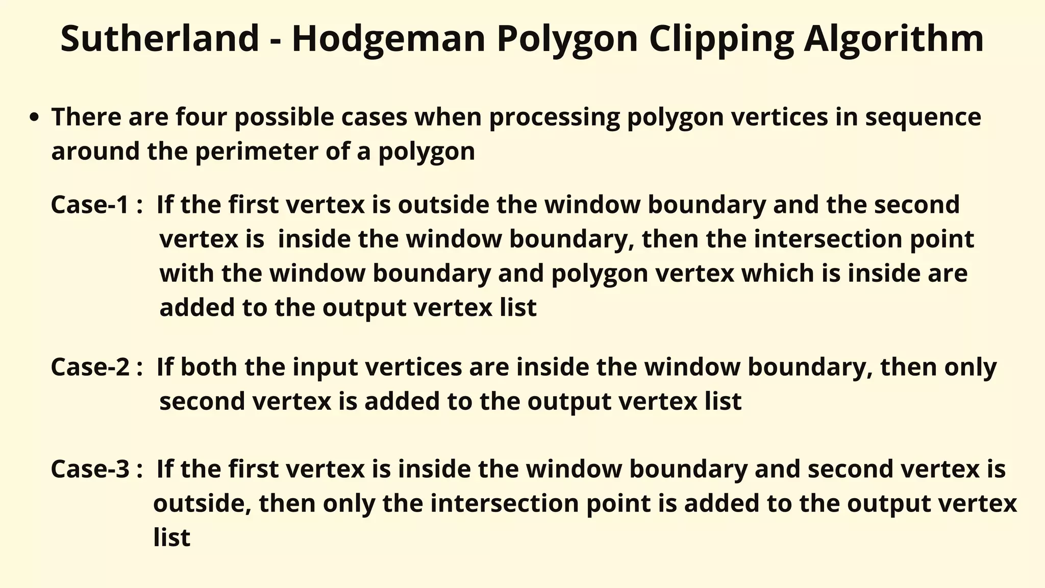
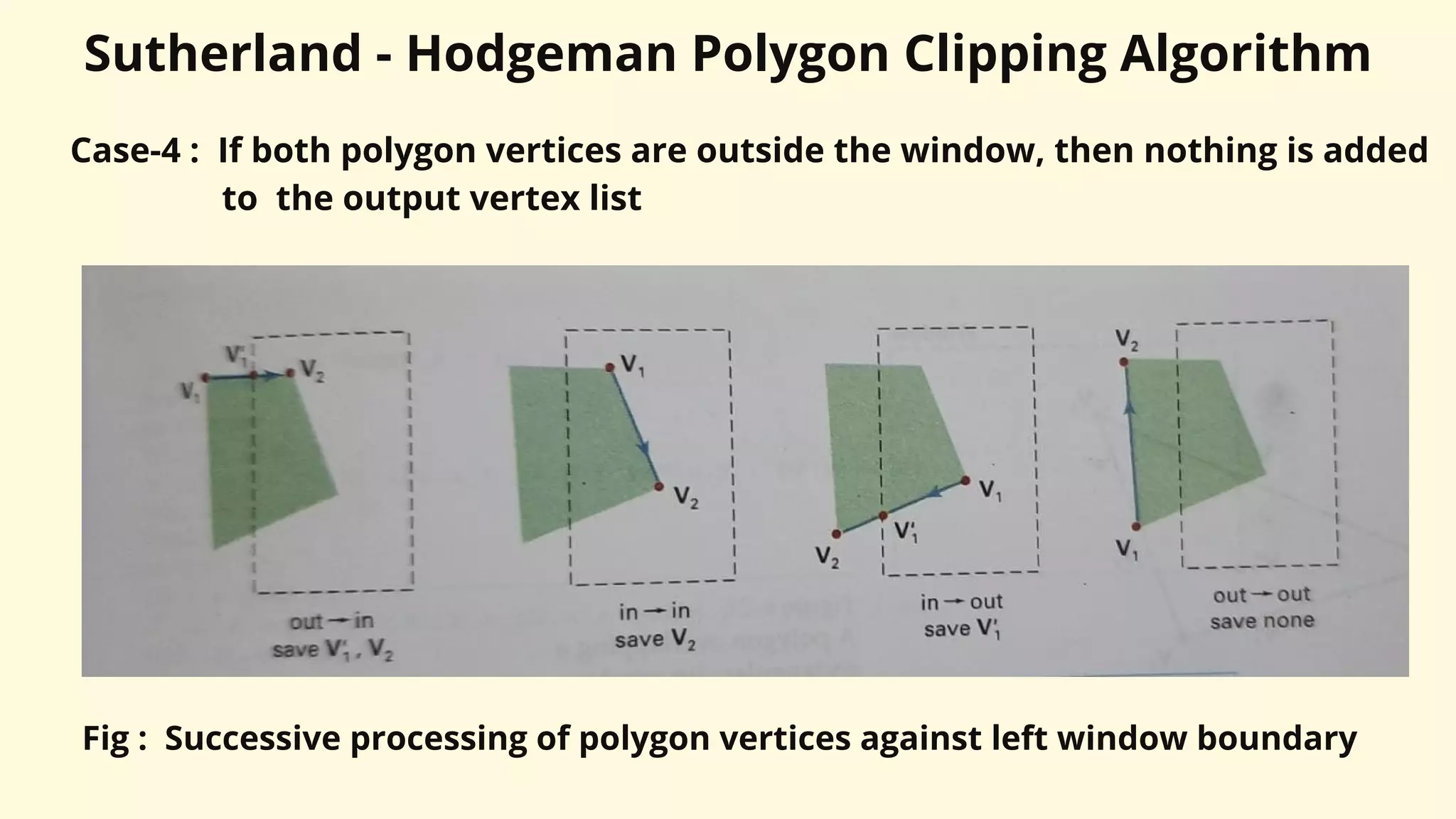
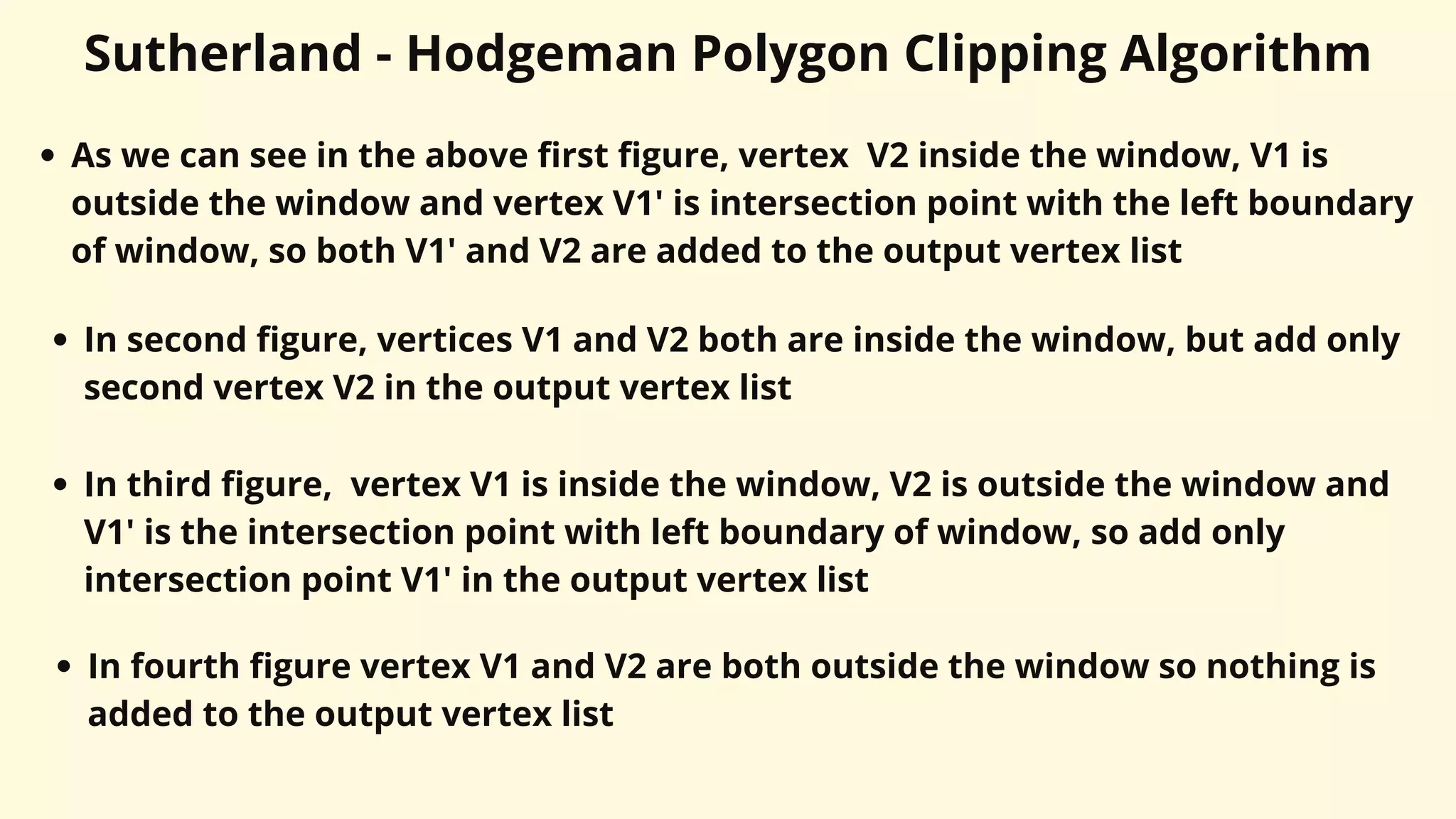
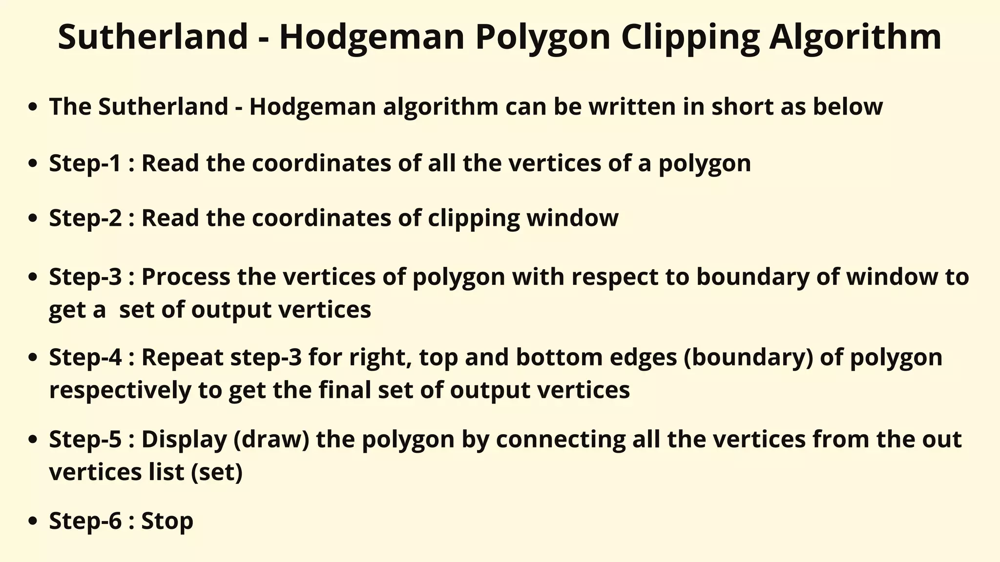
Download as PDF, PPTX


![Cyrus Beck Line Clipping Algorithm
P1
P2
f
n
n
n
n.[ P(t) - f ] > 0
n.[ P(t) - f ] = 0
n.[ P(t) - f ] < 0
Clipping edge
(clipping boundary )
x
y
f
0
n
R-conves region
Convex region, boundary point
and inner normal](https://image.slidesharecdn.com/unit-ivwindowingandclipping-230316142407-744dde0c/75/Unit-IV-Windowing-and-Clipping-pdf-45-2048.jpg)
![Cyrus Beck Line Clipping Algorithm
Consider a convex clipping region R, f is a boundary point of the convex region R
and n is an inner normal for one of its boundaries as shown in above figure
Then we can distinguish (decide) in which region a point lie by looking at the
value of the dot product, n.[P(t) – f ], as shown in Fig.
If dot product is negative i.e.,
n.[P(t) – f ] < 0 ... (2)
then the vector [P(t) – f ] is pointed away from the interior of R.
If dot product is zero i.e.,
n.[P(t) – f ] = 0 ... (3)
then the vector [P(t) – f ] is pointed parallel to the plane containing f and
perpendicular (90 degree) to the normal](https://image.slidesharecdn.com/unit-ivwindowingandclipping-230316142407-744dde0c/75/Unit-IV-Windowing-and-Clipping-pdf-46-2048.jpg)
![Cyrus Beck Line Clipping Algorithm
If dot product is positive i.e.,
n.[P(t) – f ] > 0 ... (4)
then the vector [P(t) – f ] is pointed towards the interior of R.
As shown in Fig. if the point f lies in the boundary plane or edge for which n is
the inner normal, then that point t on the line P(t) which satisfies,
n.[P(t) – f ] = 0 condition is the intersection of the line with the boundary edge
To get the formal statement of the Cyrus-Beck algorithm we substitute value of
P(t) in equation 3
n . [P(t) – f ] = n . [P1 + (P2 – P1)t – f ] = 0 ... (5)
The relation should be applied for each boundary plane or edge of the window
to get the intersection points](https://image.slidesharecdn.com/unit-ivwindowingandclipping-230316142407-744dde0c/75/Unit-IV-Windowing-and-Clipping-pdf-47-2048.jpg)
![Cyrus Beck Line Clipping Algorithm
Thus in general form equation (5) can be written as,
ni . [P1 + (P2 – P1)t – fi ] = 0 ... (6)
where, i is edge number
Solving equation (6) we get,
ni . [P1 – fi ] + ni . (P2 –P1)t = 0 ... (7)
Here the vector P2 – P1 defines the direction of the line, the direction of the line
is important to correctly identify the visibility of the line
The vector P1 - fi is proportional to the distance from the end point of the line
to the boundary point
Let us define,
D = P2 – P1 as the direction of a line and
Wi = P1 – fi as weighting factor](https://image.slidesharecdn.com/unit-ivwindowingandclipping-230316142407-744dde0c/75/Unit-IV-Windowing-and-Clipping-pdf-48-2048.jpg)
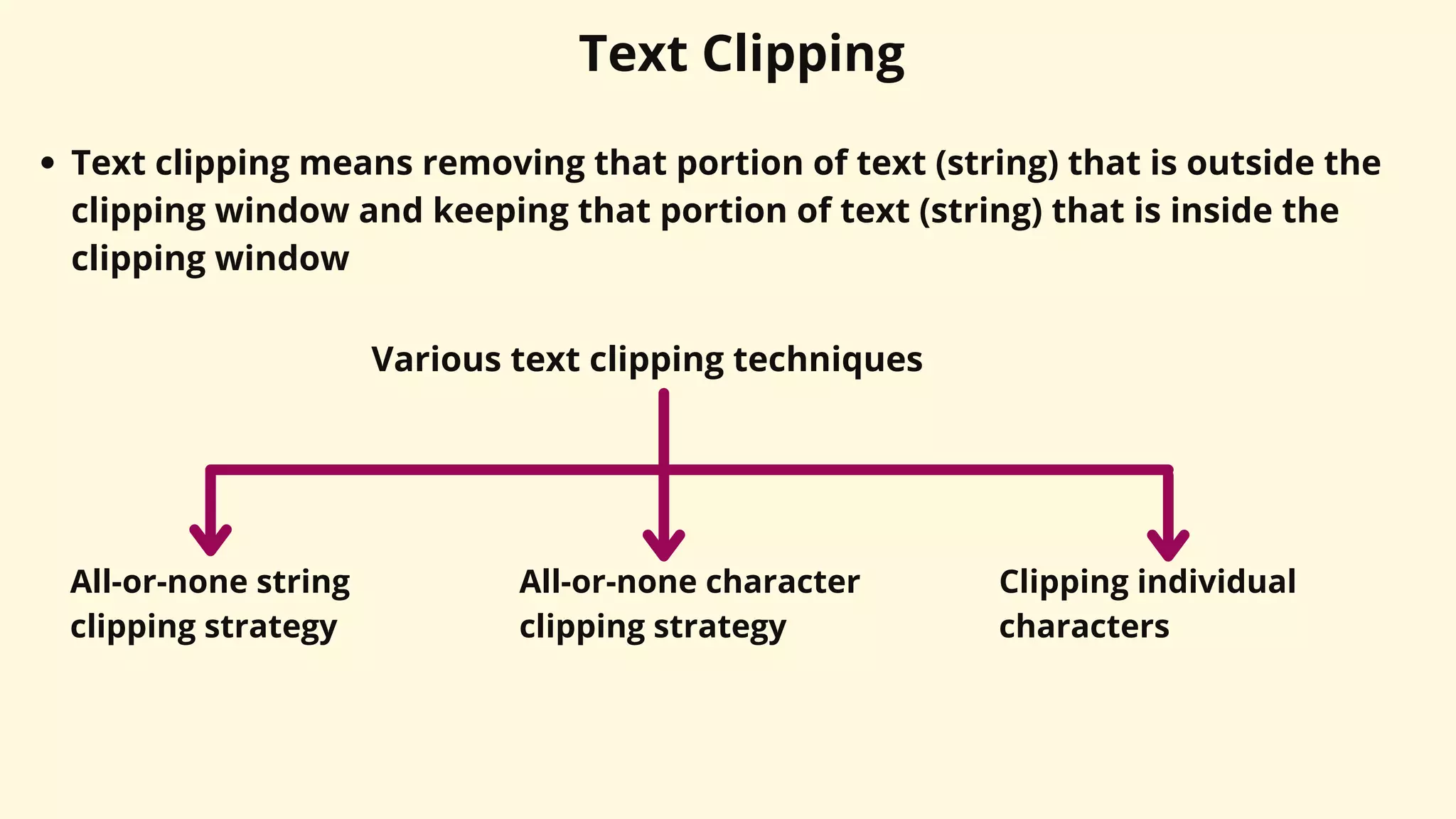
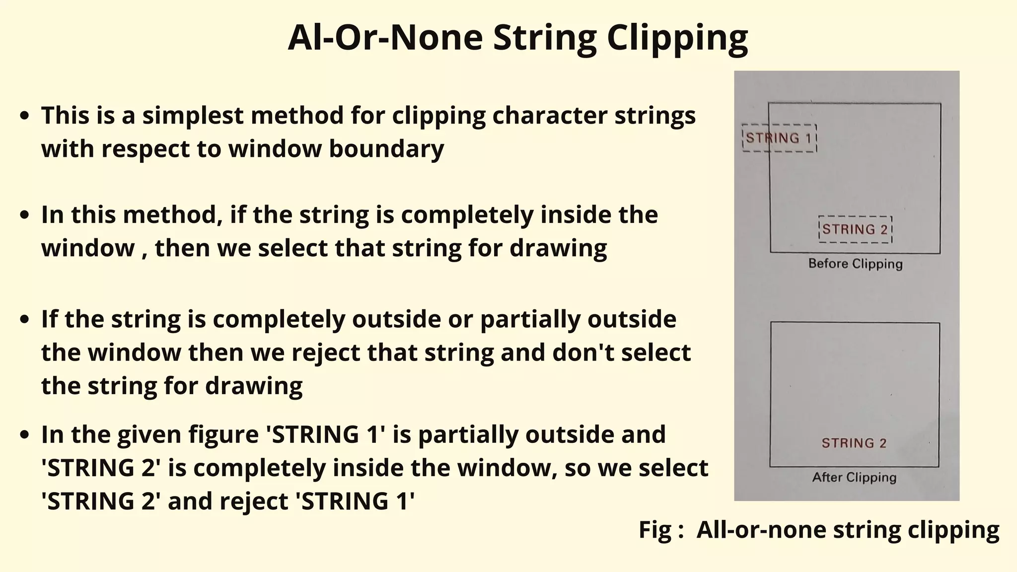
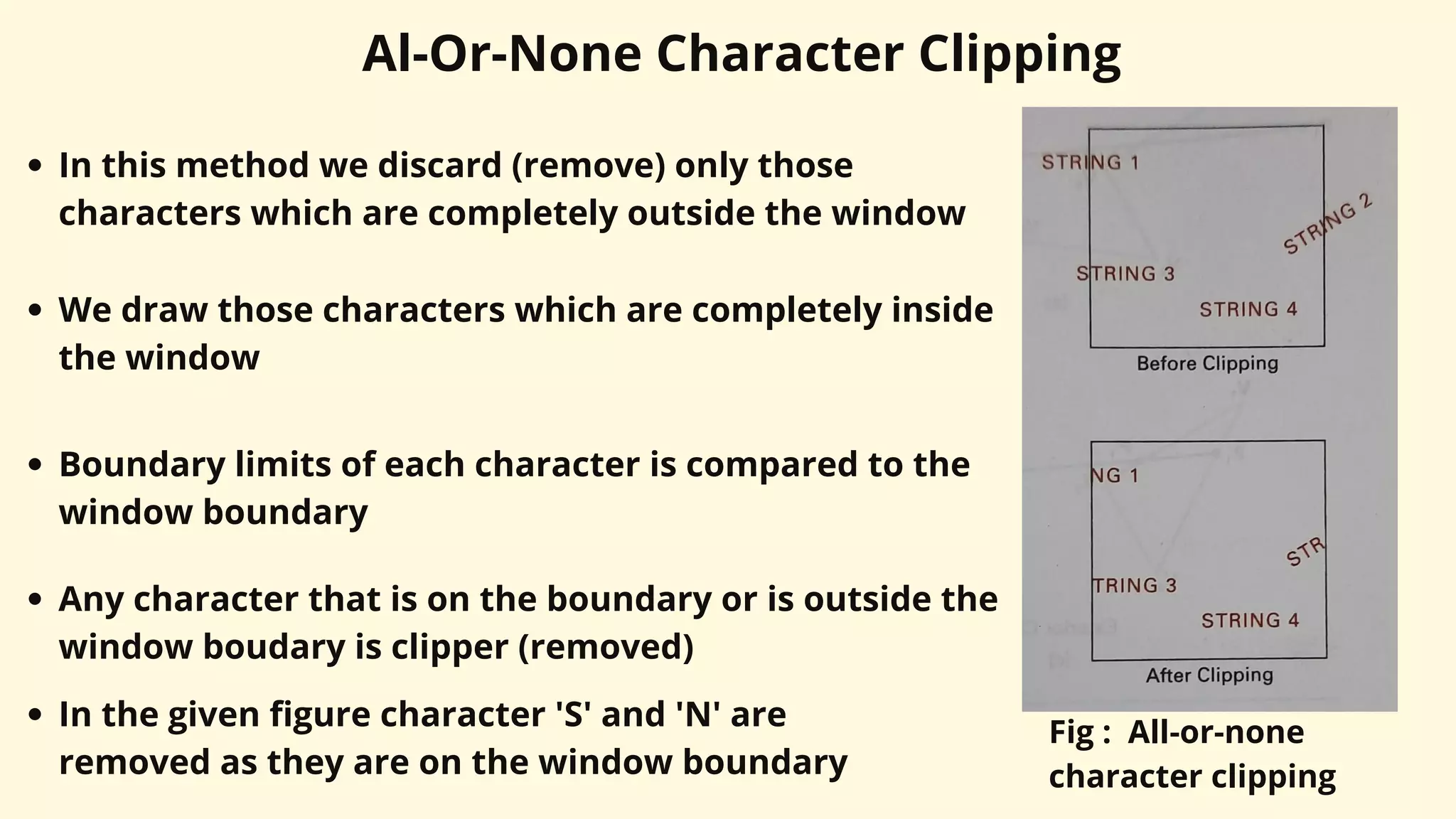
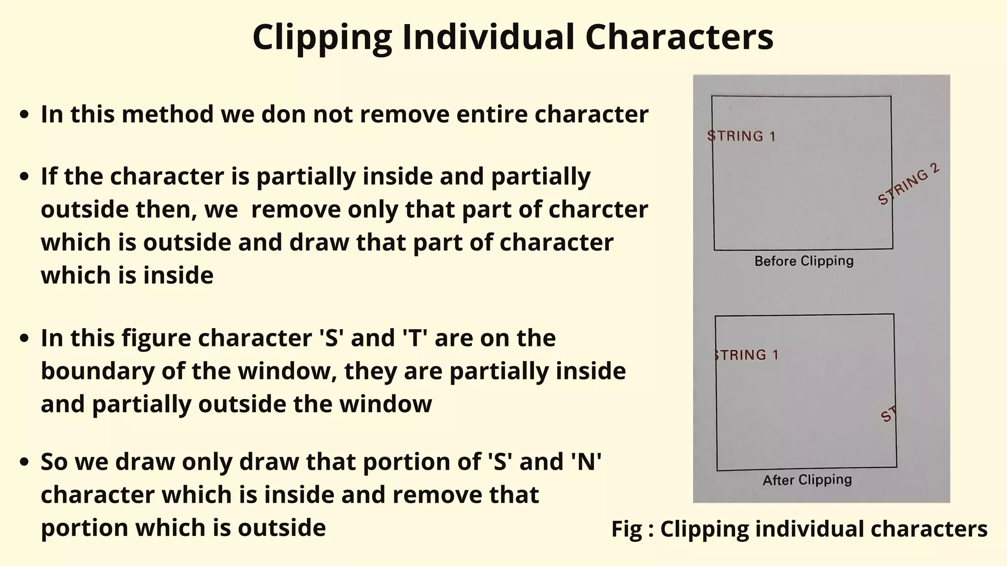


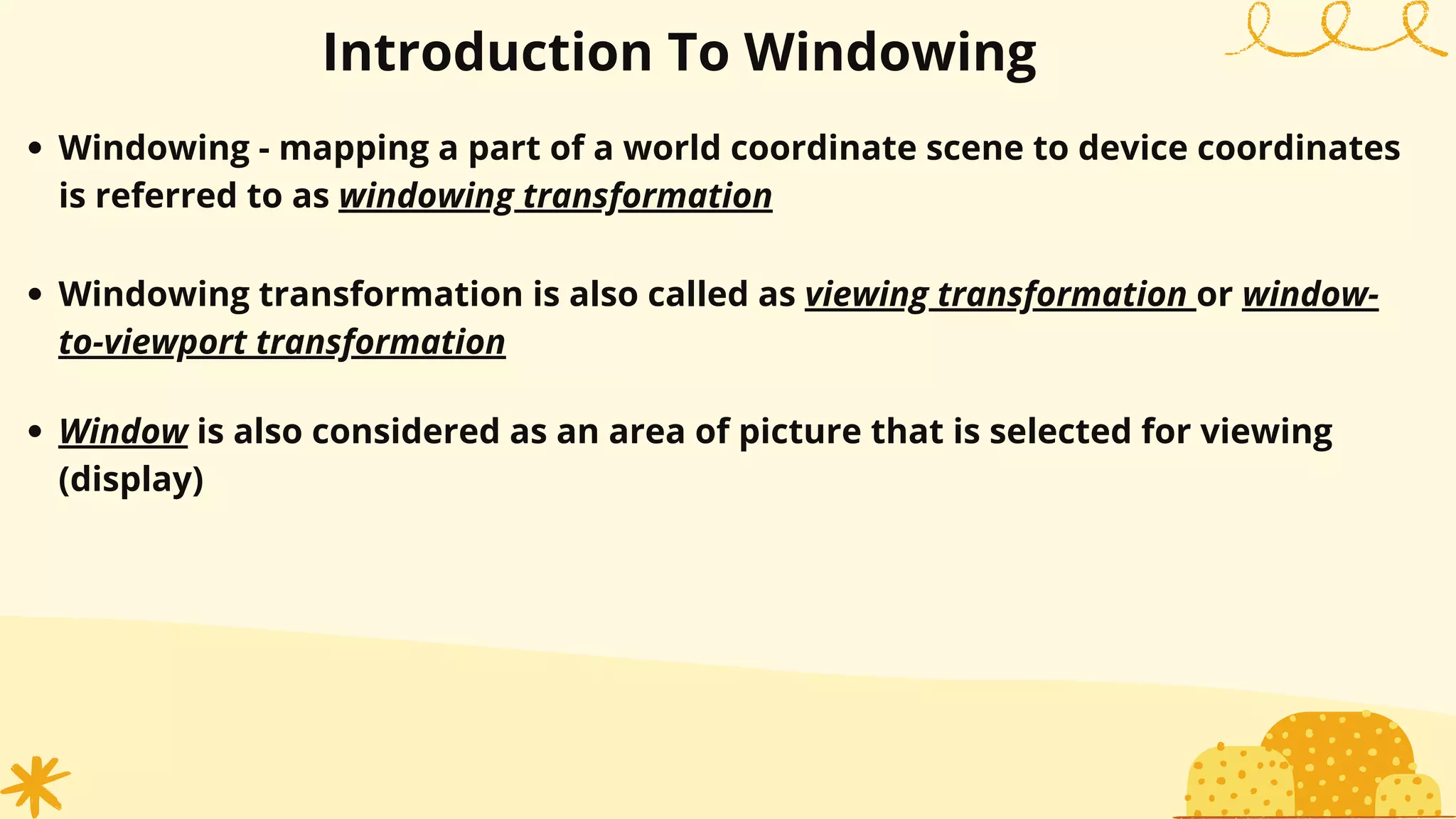
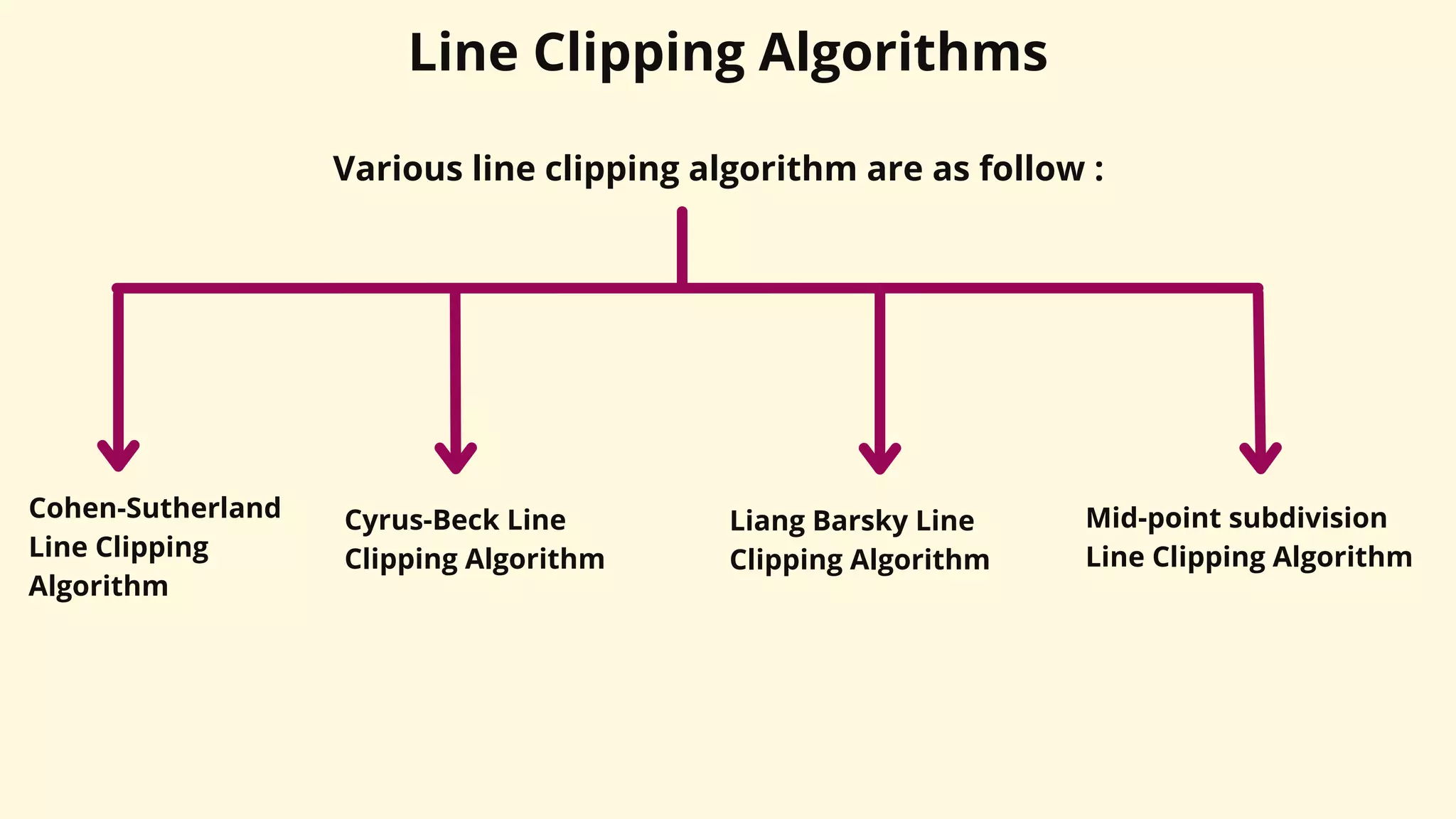
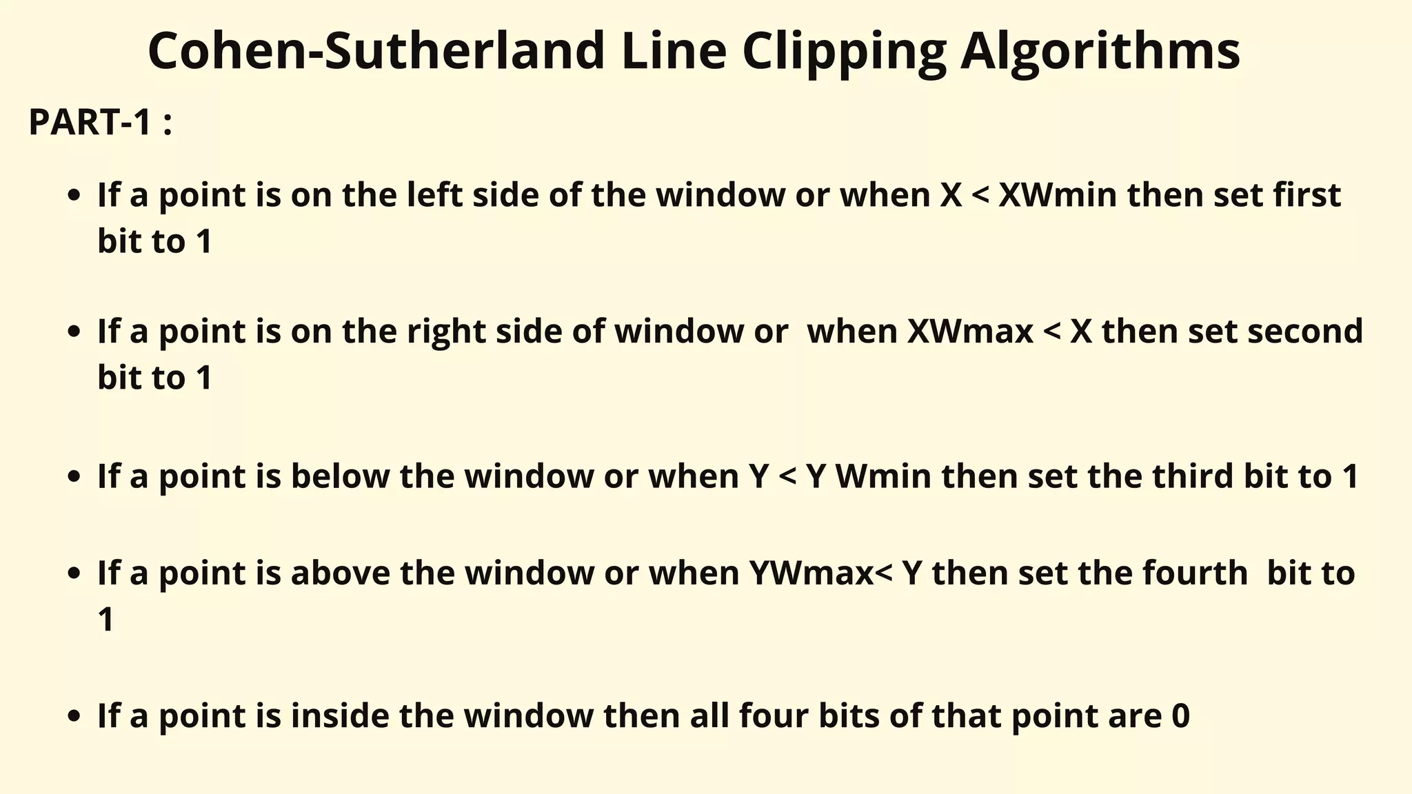
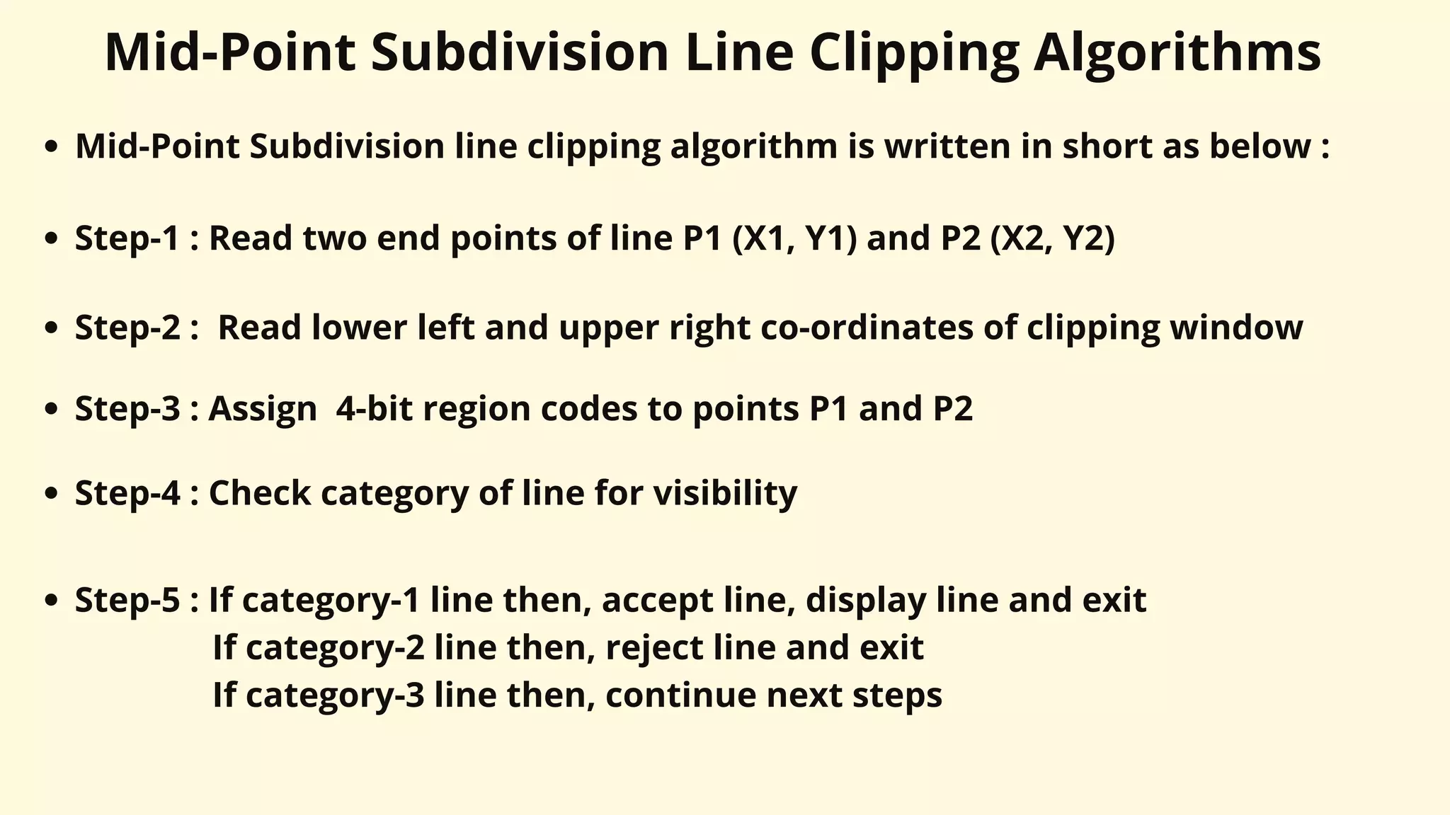
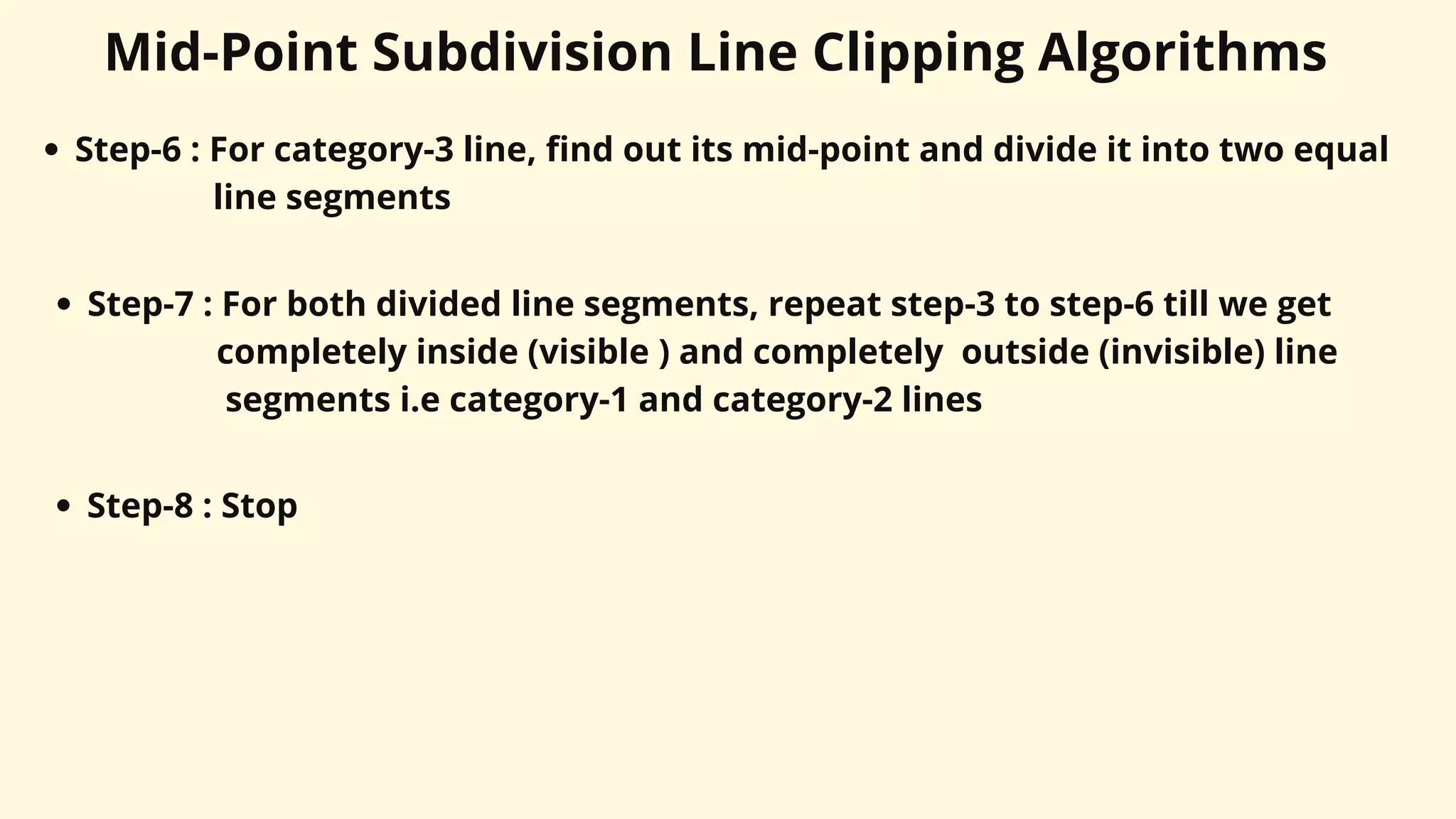
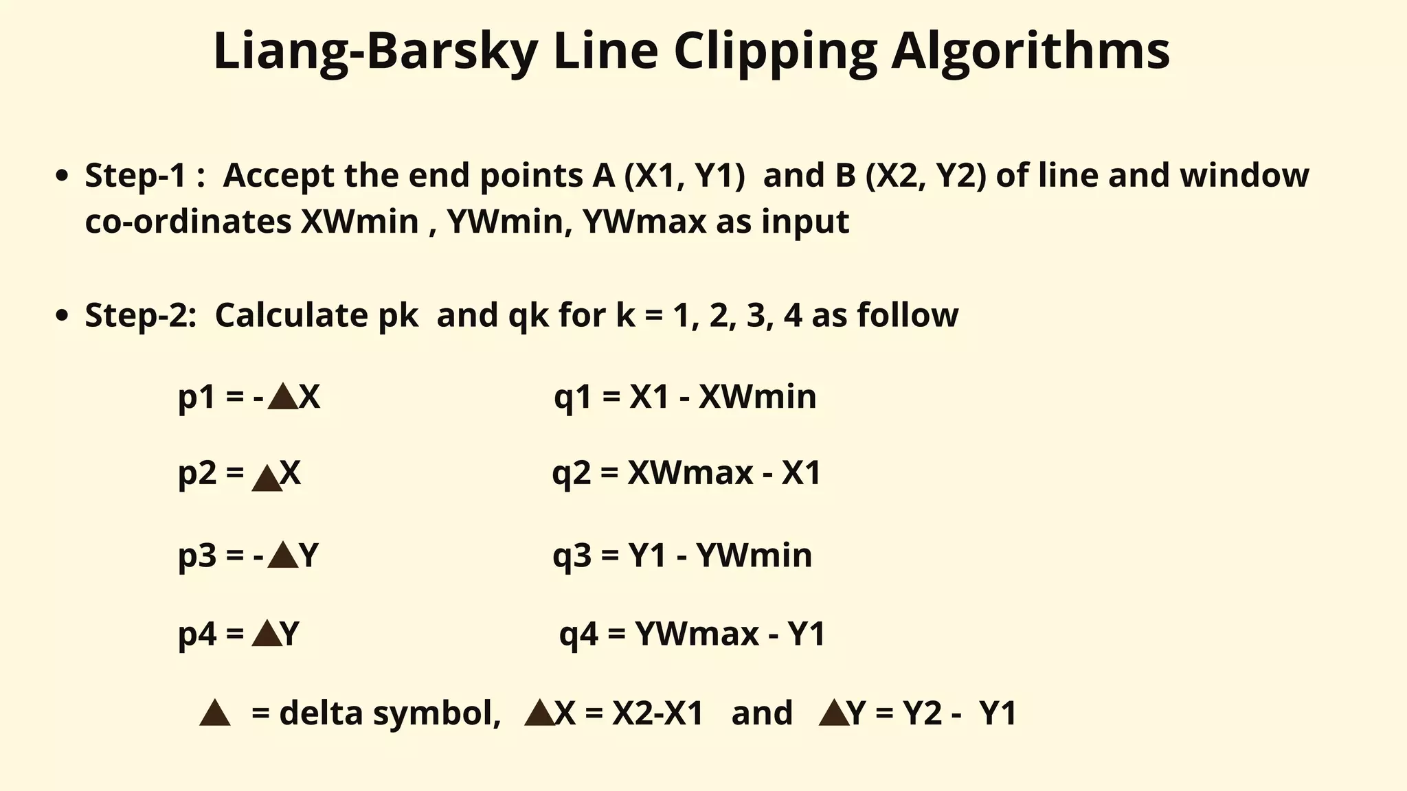
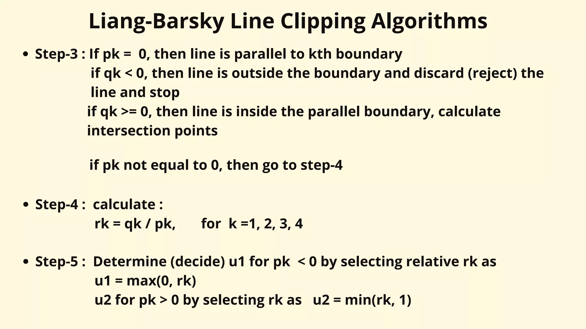
The document provides an overview of windowing and clipping in computer graphics, detailing transformations from world coordinates to device coordinates and the various algorithms for clipping lines and points. It explains concepts such as windows, viewports, and the processes involved in clipping objects within specified regions. Various clipping algorithms, including Cohen-Sutherland, mid-point subdivision, and Liang-Barsky, are described along with their steps and applications.