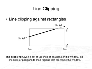
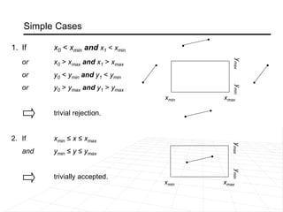
The document discusses different techniques for clipping lines and polygons to a viewing window or clipping region.
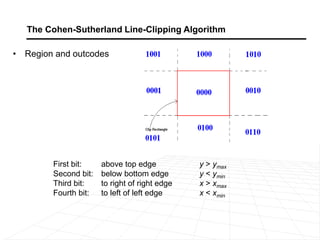
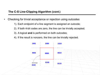
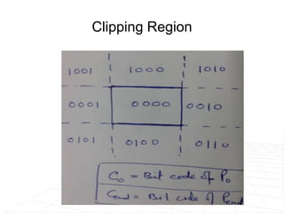
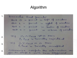
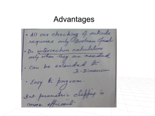
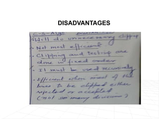
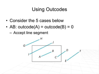
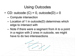
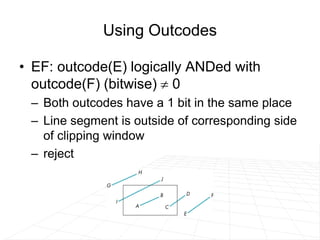
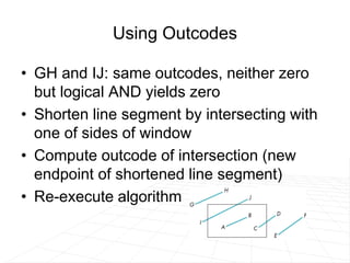
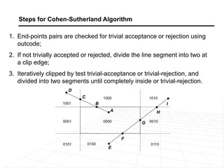
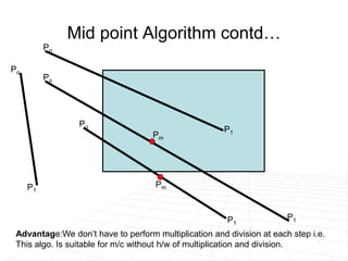
It describes line clipping algorithms like Cohen-Sutherland that use outcodes to quickly reject lines outside the clipping region or clip lines intersecting the boundary. It also discusses the midpoint subdivision algorithm for line clipping.
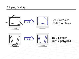
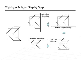
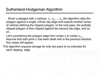
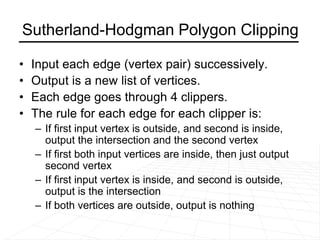
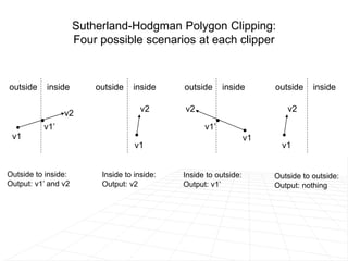
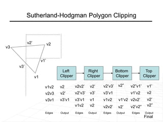
For polygon clipping, it explains the Sutherland-Hodgeman algorithm which clips polygons against each window edge one by one, dividing the polygon into smaller clipped polygons inside the viewing region.