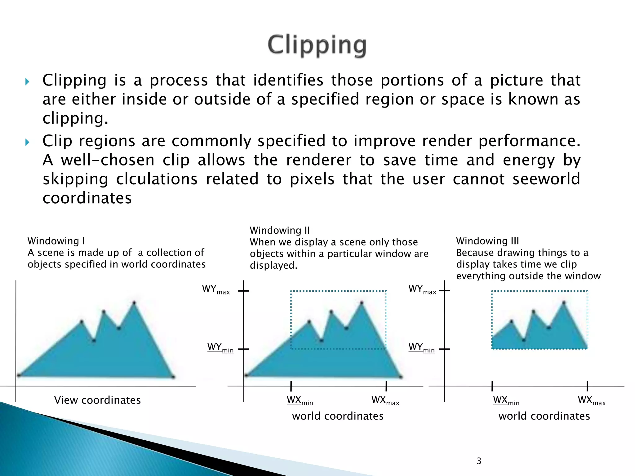
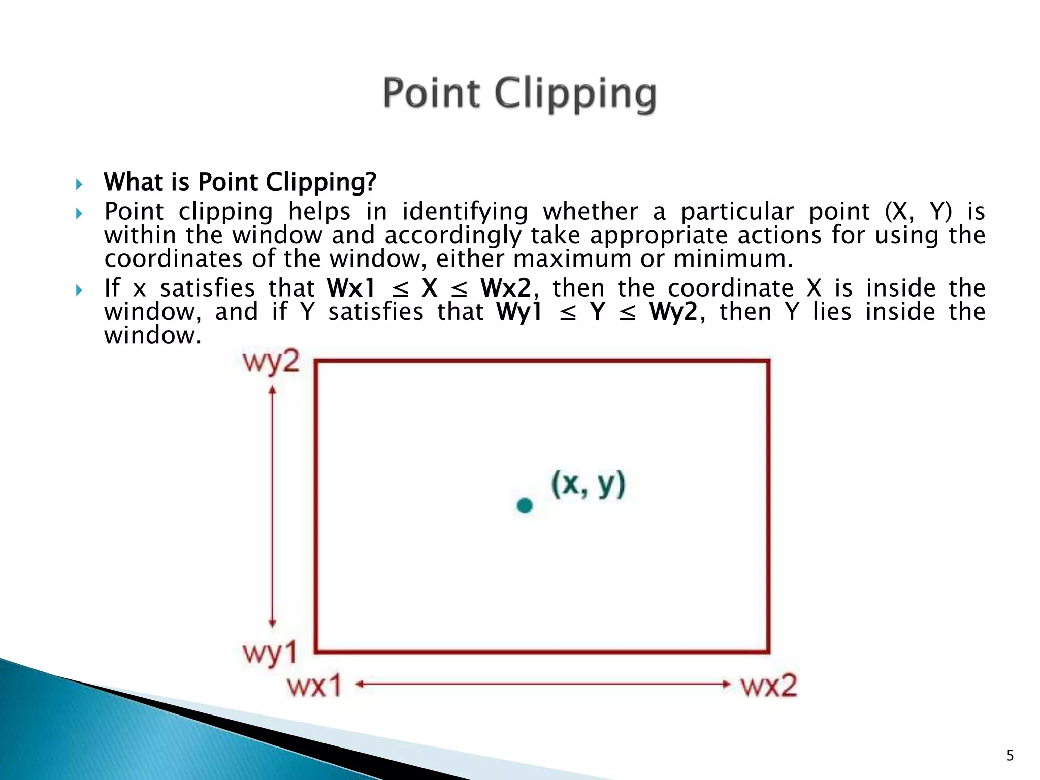
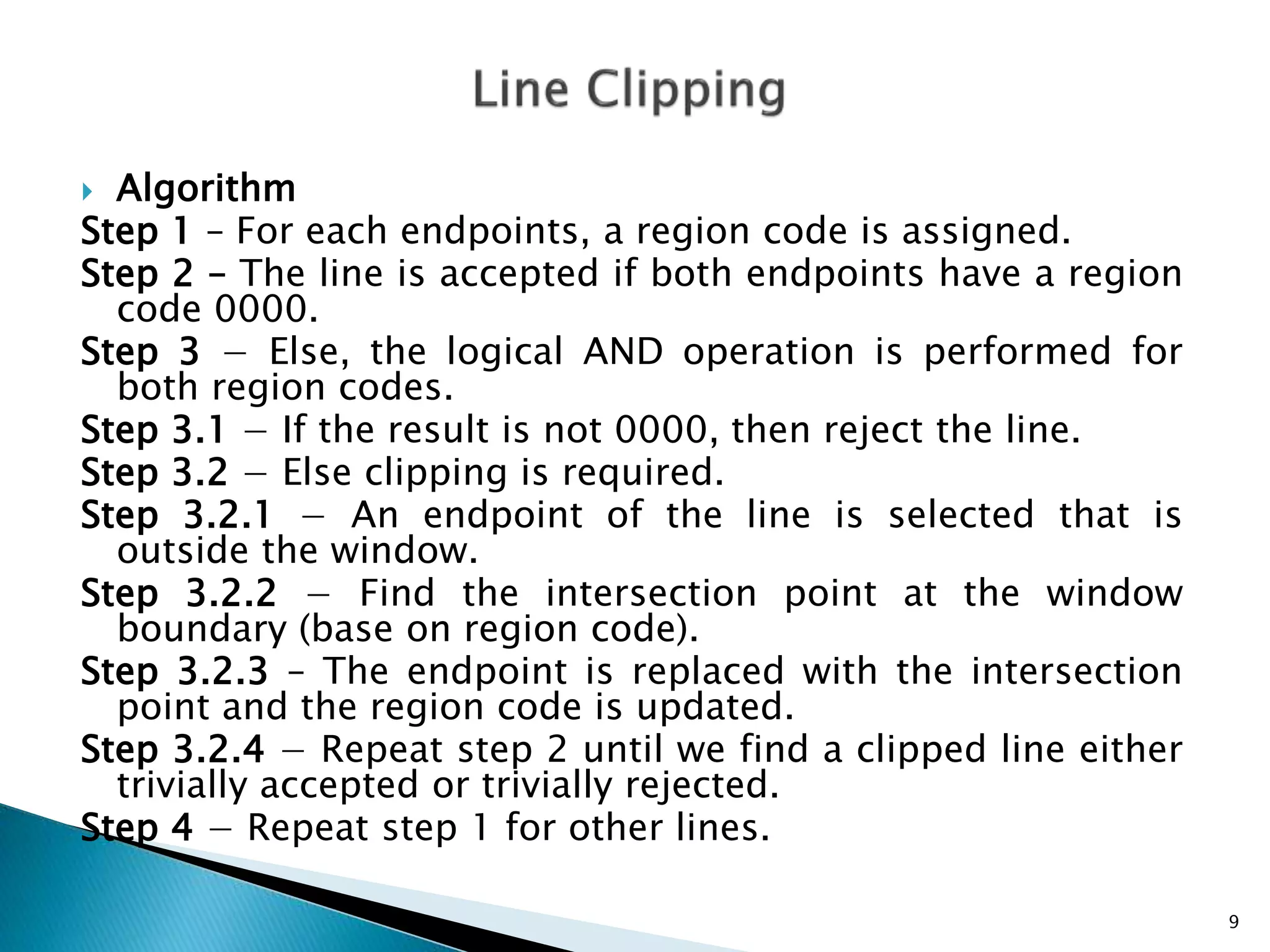
Clipping is a process that extracts portions of data or scenes inside a specified clipping region. It uses endpoint codes, which assign a 4-bit code to line endpoints to indicate if they are inside or outside the clipping window. One algorithm is the Cohen-Sutherland algorithm which uses these endpoint codes to test if lines are completely inside, completely outside, or intersect the clipping window. Another is the Mid-Point Subdivision algorithm which avoids directly calculating line-window intersections by performing a binary search via dividing lines at their midpoint.
This slide contain description about the line, circle and ellipse drawing algorithm in computer graphics. It also deals with the filled area primitive.
The document discusses different techniques for filling polygons, including boundary fill, flood fill, and scan-line fill methods. It provides details on how each technique works, such as using a seed point and filling neighboring pixels for boundary fill, replacing all pixels of a selected color for flood fill, and drawing pixels between edge intersections for each scan line for scan-line fill. Examples are given to illustrate the filling process for each method.
Bresenham's line algorithm is an efficient method for drawing lines on a digital display. It works by calculating the next pixel coordinate along the line using integer math only. This avoids complex floating point calculations. It starts at the initial coordinate and iteratively calculates the next x,y coordinate using integer addition and comparisons until it reaches the final endpoint.
Cohen-Sutherland Line Clipping Algorithm:
When drawing a 2D line on screen, it might happen that one or both of the endpoints are outside the screen while a part of the line should still be visible. In that case, an efficient algorithm is needed to find two new endpoints that are on the edges on the screen, so that the part of the line that's visible can now be drawn. This way, all those points of the line outside the screen are clipped away and you don't need to waste any execution time on them.
A good clipping algorithm is the Cohen-Sutherland algorithm for this solution.
By,
Maruf Abdullah Rion
Polygon is a figure having many slides. It may be represented as a number of line segments end to end to form a closed figure.
The line segments which form the boundary of the polygon are called edges or slides of the polygon.
The end of the side is called the polygon vertices.
Triangle is the most simple form of polygon having three side and three vertices.
The polygon may be of any shape.
The document discusses image segmentation and the use of segments to structure image display. It describes how a display file can be divided into segments using a segment table. The segment table either uses arrays or linked lists to store segment information like start position, size, and attributes. Algorithms are provided for creating, closing, deleting, and renaming segments to dynamically manage the image display. Visibility attributes allow hiding or showing segments as needed.
This document discusses the Digital Differential Analyzer (DDA) algorithm, which is a basic line drawing algorithm used in computer graphics. The DDA algorithm uses slope-intercept form (y=mx+b) to incrementally calculate pixel positions along the line between two points. It handles cases where the slope is less than or greater than 1 by incrementing either the x or y coordinate by 1 at each step. The DDA algorithm is simple to implement but requires floating point calculations and has orientation dependency issues.
Clipping is a procedure that identifies portions of an image that are inside or outside a specified region. The Cohen-Sutherland algorithm is commonly used for clipping lines. It assigns binary codes to line endpoints to determine if they are fully inside, outside or intersect the clipping region. If an endpoint is outside, it calculates the intersection with the clipping boundary. This clips the line segment down to the visible portion within the region.
Mid point line Algorithm - Computer GraphicsDrishti Bhalla
The document describes the midpoint line algorithm for plotting lines on a grid. It works by calculating the midpoint between each set of pixels and determining if it falls above or below the line to choose the next pixel. It only requires integer calculations, avoiding errors from division or multiplication. The algorithm is derived step-by-step and an example is provided to demonstrate how it is implemented to plot a line between two points.
Clipping algorithms identify portions of an image that are inside or outside a specified clipping region. They are used to extract a defined scene for viewing, identify visible surfaces, and perform other drawing and display operations. Common types of clipping include point, line, polygon, and curve clipping. Algorithms like Cohen-Sutherland and mid-point subdivision use codes and binary subdivision to efficiently determine which image portions are visible and should be displayed.
Visible surface detection in computer graphicanku2266
Visible surface detection aims to determine which parts of 3D objects are visible and which are obscured. There are two main approaches: object space methods compare objects' positions to determine visibility, while image space methods process surfaces one pixel at a time to determine visibility based on depth. Depth-buffer and A-buffer methods are common image space techniques that use depth testing to handle occlusion.
AND-OR search graphs are used to represent problem solving and decomposition. The nodes represent states or goals, and successors are labeled as either AND or OR branches. AND branches indicate subgoals that must all be achieved, while OR branches represent alternative subgoals that could achieve the parent goal. AO* is an AND-OR graph algorithm that can find multiple solutions by combining AND and OR branches, but does not always find an optimal solution as it may not explore all possibilities once a solution is found. In contrast, A* is an OR graph algorithm that finds a single optimal solution by guaranteeing to explore all possibilities.
The Sutherland-Hodgman algorithm clips polygons by clipping against each edge of the clipping window in a specific order: left, top, right, bottom. It works by testing each edge of the polygon against the clipping window boundary and either keeping or discarding vertices based on whether they are inside or outside the window. The algorithm results in a clipped polygon that only includes vertices and edge intersections that are inside the clipping window.
This document discusses different techniques for computer graphics clipping. It describes point clipping, line clipping using the Cohen-Sutherland and Liang-Barsky algorithms, area/polygon clipping using the Sutherland-Hodgman and Weiler-Atherton algorithms, curve clipping, and text clipping. Various preliminary tests and intersection calculations are used to identify and remove graphic elements that are outside the clipping region.
Virtual Memory
• Copy-on-Write
• Page Replacement
• Allocation of Frames
• Thrashing
• Operating-System Examples
Background
Page Table When Some PagesAre Not in Main Memory
Steps in Handling a Page Fault
The sutherland hodgeman polygon clipping algorithmMani Kanth
The document discusses the Sutherland Hodgeman polygon clipping algorithm. It is used to clip a polygon by specifying a clipping window. The algorithm clips the vertices of the polygon against each edge of the clipping window by finding intersection points. If an edge is not completely inside the clipping window, the portion outside is clipped off. An example is provided to demonstrate clipping a polygon ABCDE against a clipping window PQRS.
The depth buffer method is used to determine visibility in 3D graphics by testing the depth (z-coordinate) of each surface to determine the closest visible surface. It involves using two buffers - a depth buffer to store the depth values and a frame buffer to store color values. For each pixel, the depth value is calculated and compared to the existing value in the depth buffer, and if closer the color and depth values are updated in the respective buffers. This method is implemented efficiently in hardware and processes surfaces one at a time in any order.
The document discusses window to viewport transformation. It defines a window as a world coordinate area selected for display and a viewport as a rectangular region of the screen selected for displaying objects. Window to viewport mapping requires transforming coordinates from the window to the viewport. This involves translation, scaling and another translation. Steps include translating the window to the origin, resizing it based on the viewport size, and translating it to the viewport position. An example transforms a sample window to a viewport through these three steps.
The Cyrus-Beck algorithm is used for line clipping against non-rectangular convex polygons. It uses a parametric equation to find the intersection point of the line with the polygon boundary. The algorithm calculates the time values for the line endpoints at each polygon edge, then uses those times in the parametric equation to find the clipped line segment P'0 and P'1 that is visible within the polygon clipping window.
The Cohen-Sutherland algorithm divides the plane into 9 regions and uses 4-bit codes to encode whether each endpoint of a line segment is left, right, above, or below the clipping window. It then uses the endpoint codes to either trivially accept or reject the line segment, or perform clipping by calculating the intersection point of the line with the window boundary and replacing the outside endpoint. The main steps are to assign codes to endpoints, AND the codes to check for trivial acceptance or rejection, clip by replacing outside endpoints if needed, and repeating for other line segments.
The document describes the components and operation of a raster scan graphics display system. A video controller accesses a frame buffer in system memory to refresh the screen. It performs operations like retrieving pixel intensities from different memory areas and using two frame buffers to allow refreshing one screen while filling the other for animation. A raster scan display processor can digitize graphics into pixel intensities for storage in the frame buffer to offload this processing from the CPU.
This document discusses stacks and queues as linear data structures. It defines stacks as last-in, first-out (LIFO) collections where the last item added is the first removed. Queues are first-in, first-out (FIFO) collections where the first item added is the first removed. Common stack and queue operations like push, pop, insert, and remove are presented along with algorithms and examples. Applications of stacks and queues in areas like expression evaluation, string reversal, and scheduling are also covered.
This document discusses different algorithms for filling polygons in computer graphics, including the scan-line fill algorithm, boundary fill algorithm, and flood fill algorithm. The scan-line fill algorithm involves horizontally scanning a polygon from bottom to top and identifying edge intersections with the scan line. The boundary fill algorithm starts at an interior point and recursively fills outward until the boundary color is encountered. The flood fill algorithm replaces all pixels of a specified interior color with a fill color within connected regions. Pseudocode and examples are provided for each algorithm.
This document discusses various page replacement algorithms used in operating systems. It begins with definitions of paging and page replacement in virtual memory systems. There are then overviews of 12 different page replacement algorithms including FIFO, optimal, LRU, NRU, NFU, second chance, clock, and random. The goal of page replacement algorithms is to minimize page faults. The document provides examples and analyses of how each algorithm approaches replacing pages in memory.
The Lian-Barsky algorithm is a line clipping algorithm. This algorithm is more efficient than Cohen–Sutherland line clipping algorithm and can be extended to 3-Dimensional clipping. This algorithm is considered to be the faster parametric line-clipping algorithm. The following concepts are used in this clipping:
The parametric equation of the line.
The inequalities describing the range of the clipping window which is used to determine the intersections between the line and the clip window.
Clipping is a process used in computer graphics to determine the visible and invisible portions of an image or object when only part of it can be displayed in the viewing area. It works by extracting the desired visible portion and discarding anything outside the viewing area. Some key applications of clipping include identifying visible areas of 3D objects, creating objects using solid modeling, and drawing and manipulation operations. The Cohen-Sutherland algorithm is commonly used for line clipping, where it assigns region codes to line endpoints and finds the intersection points of any partially visible lines to clip them to the visible region.
Clipping is a technique that identifies parts of an image that are inside or outside a defined clipping region or window. There are different types of clipping including point, line, polygon, curve, and text clipping. The Cohen-Sutherland algorithm is commonly used for line clipping. It assigns 4-bit codes to line endpoints to determine if they are fully inside, outside, or intersect the clipping window boundary. Intersecting line segments are then subdivided and clipped. Midpoint subdivision is another algorithm that divides partially visible lines at their midpoint into shorter segments.
1. Clipping is a procedure that identifies parts of an image that are inside or outside a specified region, called the clip window. Parts inside the window are displayed, while outside parts are discarded.
2. There are different types of clipping like point, curve, text, and line clipping. Line clipping involves testing if line segments are fully inside/outside the window, and calculating intersections if they cross window boundaries.
3. Popular line clipping algorithms like Cohen-Sutherland and Liang-Barsky assign codes to line endpoints to quickly determine if lines are fully in/out of the window without calculating intersections. They find intersection points to clip lines that cross window edges.
he capability that show some part of object internal a specify window is called windowing and a rectangular region in a world coordinate system is called window. ... Points and lines which are outside the window are "cut off" from view. This process of "cutting off" parts of the image of the world is called Clipping.
The Cohen-Sutherland line clipping algorithm clips lines to a rectangular viewport by assigning region codes to line endpoints using 4 bits to represent above, below, left of, and right of the viewport. It then clips lines by calculating the intersection of the line with viewport edges if one endpoint is inside and one outside, replacing endpoints until the line is fully inside or outside. This allows only visible portions of lines to be rendered, improving graphics performance. The algorithm handles arbitrary clipping windows efficiently and is easy to implement, though it only works for line clipping, not polygons or curves.
The Cohen-Sutherland line clipping algorithm clips lines to a rectangular viewport by assigning region codes to line endpoints using 4 bits to represent above, below, left of, and right of the viewport. It tests the region codes of endpoints to determine if lines are fully inside, fully outside, or partially inside the viewport. If partially inside, it calculates intersection points with the viewport edges and replaces endpoints to clip the line. This efficient algorithm is commonly used in computer graphics, CAD, and image processing to optimize rendering by only displaying visible line segments.
The Cohen-Sutherland line clipping algorithm clips lines to a rectangular viewport by assigning region codes to line endpoints using 4 bits to represent above, below, left of, and right of the viewport. It tests the region codes of endpoints to determine if lines are fully inside, fully outside, or partially inside the viewport. If partially inside, it calculates intersection points with the viewport edges and replaces endpoints to clip the line. This efficient algorithm is commonly used in computer graphics and CAD for line clipping and cropping images.
The document discusses different types of clipping techniques used in computer graphics. It describes clipping as identifying portions of an image that are inside or outside a specified region. There are different types of clipping including point, line, area/polygon, curve, and text clipping. Line clipping algorithms like Cohen-Sutherland and Liang-Barsky are described. Polygon clipping uses the Sutherland-Hodgeman algorithm. Window-to-viewport coordinate transformation maps a window region to a viewport using scaling and translation to maintain relative proportions.
This document summarizes line clipping techniques in computer graphics. It discusses point clipping, line clipping, and area clipping. For line clipping, it describes the three situations of both endpoints inside the window, one endpoint inside and one outside, and both outside. It then explains the brute force and Cohen-Sutherland algorithms for line clipping. The Cohen-Sutherland algorithm uses region codes to efficiently determine which lines are fully inside, fully outside, or need clipping against window boundaries. It provides examples of applying the algorithm to different line scenarios. Finally, it compares the brute force and Cohen-Sutherland methods, noting Cohen-Sutherland is faster but more complex.
The document discusses different techniques for clipping lines and polygons to a viewing window or clipping region.
It describes line clipping algorithms like Cohen-Sutherland that use outcodes to quickly reject lines outside the clipping region or clip lines intersecting the boundary. It also discusses the midpoint subdivision algorithm for line clipping.
For polygon clipping, it explains the Sutherland-Hodgeman algorithm which clips polygons against each window edge one by one, dividing the polygon into smaller clipped polygons inside the viewing region.
The document discusses different techniques for line clipping, including:
1. The Cohen-Sutherland line clipping algorithm which divides the screen into 9 regions and clips lines based on which regions their endpoints fall into.
2. Midpoint subdivision is an alternative that recursively divides lines at the midpoint until they can be fully classified.
3. Intersection calculations determine where lines intersect clipping boundaries.
Polygon clipping extends these ideas, testing vertex pairs and either outputting intersections or vertices as needed to clip the polygon shape.
The document discusses different line clipping algorithms:
1. Cohen-Sutherland line clipping algorithm assigns a region code to endpoints and clips lines based on whether both endpoints are inside, outside, or intersect the clipping region.
2. Midpoint subdivision recursively divides lines at the midpoint until all segments are fully inside or outside the clipping region.
3. Sutherland-Hodgeman polygon clipping algorithm tests vertex pairs and saves intersections or vertices to the output based on four cases of vertices lying inside or outside the clipping window.
The document discusses 2D clipping techniques used in computer graphics. It describes several types of 2D clipping including point clipping, line clipping, polygon/area clipping, text clipping and curve clipping. For line clipping, it explains Cohen-Sutherland line clipping algorithm in detail. The algorithm uses region codes to classify lines as fully visible, fully clipped or partially clipped. It then performs analytical clipping of partially clipped lines by calculating intersection points with window boundaries.
Windowing and clipping are techniques used in computer graphics to select and display portions of an image or drawing. Windowing refers to selecting a region or "window" to view. The viewport defines the area on the display device where the window will be mapped. Clipping determines which parts of an image or drawing are visible within the window by dividing elements into visible and invisible portions. Common clipping techniques include point, line, polygon and curve clipping. The Cohen-Sutherland and Liang-Barsky algorithms are used for line clipping, and Sutherland-Hodgeman for polygon clipping. Midpoint subdivision is another line clipping method.
Sutherlands Cohen and Hodgeman algorithmsRohit Jain
The document discusses different algorithms for clipping graphics objects to a viewing window:
- The Cohen-Sutherland algorithm clips lines efficiently by assigning region codes to endpoints and clipping any lines where the endpoints have a common set bit in their codes.
- The Sutherland-Hodgman algorithm clips areas by comparing polygons to each boundary in turn, saving vertices that fall inside each boundary for the next clip.
- Clipping graphics objects ensures only those within the window are drawn, improving efficiency over drawing all objects in a scene.
This document discusses different techniques for line and polygon clipping. It describes 4 cases for line clipping depending on where the endpoints are located relative to the clipping area. For polygon clipping, it explains the Sutherland-Hodgeman algorithm and 4 cases for how vertices are handled depending on if they are inside or outside the clipping window. It also compares the midpoint subdivision and Cohen-Sutherland line clipping algorithms, noting that midpoint subdivision is a special case of Cohen-Sutherland that uses midpoint approximation instead of equation solving.
The ANPR (Automatic Number Plate Recognition) using ALR (Automatic line
Tracking Robot) is a system designed to help in recognition of number plates of vehicles.
This system is designed for the purpose of the security and it is a security system.
For more details
http://projectsofashok.blogspot.com/2010/04/anprautomatic-number-plate-recognition.html
This document discusses different algorithms for line and polygon clipping. It describes 4 cases for line clipping depending on where the endpoints are located relative to the clipping area. For polygon clipping, it explains the Sutherland-Hodgeman algorithm and 4 cases for processing vertices and adding them to the output list. It also introduces the midpoint subdivision algorithm for line clipping which uses binary search to iteratively subdivide lines into smaller segments for clipping.
This document discusses combinational circuits and provides examples of half adders and full adders. It defines combinational circuits as those whose outputs only depend on the current inputs. A half adder is described as having two inputs (A and B) and two outputs (sum and carry), which can add two single bits. Its truth table and logic diagram using an XOR gate and AND gate are shown. A full adder handles three inputs (A, B, and a carry input) and produces a sum and carry output based on its truth table.
The document discusses different number systems used in digital electronics, including binary, decimal, octal, and hexadecimal. It provides examples and explanations of how to convert between these number systems. In particular, it outlines the process for converting binary numbers to decimal numbers by multiplying each bit by its place value weight and summing the results. This includes approaches for fractional binary numbers and mixed binary numbers containing both integer and fractional parts.
This document discusses different types of multiplexers, including 2x1, 4x1, and 8x1 multiplexers. It provides the block diagram and truth table for each type of multiplexer. A 2x1 multiplexer has 2 inputs, 1 selection line, and 1 output. A 4x1 multiplexer has 4 inputs, 2 selection lines, and 1 output. An 8x1 multiplexer has 8 inputs, 3 selection lines, and 1 output. The logical expressions and circuits for each type of multiplexer are also provided.
Logic gates are basic building blocks of digital circuits and systems. Common logic gates include AND, OR, NOT, NAND, NOR, XOR, and XNOR gates. AND gates output 1 only if all inputs are 1, while OR gates output 1 if any input is 1. NOT gates output the inverse of the single input. NAND and NOR gates are combinations of AND/OR with NOT gates. XOR and XNOR gates output 1 only if inputs are both the same or different respectively.
The document discusses Karnaugh maps, which are a graphical technique for simplifying boolean functions. A K-map is a diagram with squares that each represent minterms or maxterms. Variables are represented along rows and columns. Groups of 1s can be combined according to grouping rules to simplify boolean expressions. The example shows a 2-variable K-map used to minimize the boolean expression XY' + X'Y + X'Y' to X' + Y'. K-maps allow boolean functions to be reduced more easily than boolean algebra.
The document discusses rules for minimizing Boolean functions using K-maps. It explains that K-maps are used to graphically represent Boolean functions according to the number of variables. Values are filled in the K-map and grouped based on several rules: groups must contain only 0s or 1s but not both; groups can overlap; groups must contain a power of 2 cells and be horizontal or vertical only; groups should be as large as possible with fewest groups overall. Examples are provided to illustrate opposite and corner grouping.
The half subtractor is a digital circuit that subtracts two single bit binary numbers and outputs the difference and borrow. It contains two inputs, A and B, and two outputs, Diff and Borrow. The Diff output is the difference of A and B, calculated as A XOR B. The Borrow output is 1 only when A is 1 and B is 0, calculated as A'B. The full subtractor expands on this to subtract three 1-bit numbers by adding a third input, Borrowin, and producing Diff and Borrow outputs based on all input combinations.
The document discusses Gray code, which is a binary numbering system where two successive numbers differ in only one bit. This reduces switching errors during transitions between numbers. Gray code is used in digital communications and applications where normal binary could produce errors. The document provides examples to show how decimal numbers convert to binary and Gray code. In binary, more bits may change between numbers, while Gray code ensures only one bit changes.
The document provides information about Prof. Neeraj Bhargava and Mrs. Pooja Dixit who work in the Department of Computer Science in the School of Engineering & System Sciences at MDS University in Ajmer, Rajasthan.
This document discusses encoders and provides examples of 4-to-2 and 8-to-3 line encoders. It defines an encoder as a combinational circuit that performs the reverse operation of a decoder, with a maximum of 2n input lines and n output lines. Truth tables and logic circuits are given for 4-to-2 and 8-to-3 line encoders. Uses of encoders include converting decimal to binary numbers to perform binary operations like addition and subtraction in digital systems.
This document discusses demultiplexers, which are combinational circuits with one input and multiple outputs. It describes 1x2 and 1x4 demultiplexers specifically. For a 1x2 demultiplexer, there are two outputs, one selection line, and a single input. The input is directed to one of the two outputs based on the selection line value. A 1x4 demultiplexer has four outputs, two selection lines, and one input. The input is directed to one of the four outputs based on the combination of values on the two selection lines. Block diagrams and truth tables are provided to illustrate the functionality of 1x2 and 1x4 demultiplexers.
The document discusses DeMorgan's theorems, which state that a NOR gate is logically equivalent to an AND gate with inverted inputs, and a NAND gate is equivalent to an OR gate with inverted inputs. DeMorgan's theorems are important in digital logic, as they allow basic gates like NAND and NOR to be used to implement more complex logic functions. The theorems are verified through truth tables.
This document discusses combinational circuits and provides examples of half adders and full adders. It defines combinational circuits as those whose outputs only depend on the current inputs. A half adder is described as having two inputs (A and B) and two outputs (sum and carry), which can add two single bits. Its truth table and logic diagram using an XOR gate and AND gate are shown. A full adder handles three inputs (A, B, Cin) to add two bits along with a carry bit, with outputs of sum and carry out. Its block diagram and truth table are presented.
The document discusses Boolean algebra, which uses binary numbers (0 and 1) to analyze and simplify digital logic circuits. It was invented by George Boole in 1854. The document outlines several important rules of Boolean algebra, including commutative, associative, distributive, identity, idempotent, complement, and double negation laws. It also discusses de Morgan's theorem and finding the dual of Boolean expressions.
Binary multiplication and division work similarly to decimal operations but use only 0s and 1s. For binary multiplication, there are four basic rules and the process involves multiplying each bit of one number by the other number and summing the results. Examples show multiplying 1010 x 101 to get 10100 and comparing the binary result to its decimal equivalent. Binary division uses long division to divide strings of binary digits. Examples demonstrate dividing several binary numbers by powers of two.
Binary arithmetic is essential for digital computers and systems. It includes four rules for binary addition and subtraction. Binary addition examples show that adding two 1s results in a 1 in the next column with a carry of 1. Binary subtraction uses borrowing to subtract binary numbers, as shown through several examples.
This document provides an overview of computer organization. It defines computer organization as how the various parts of a computer are organized and work together. It describes the main components of a computer like the CPU, memory (RAM and cache), and buses. It also discusses number systems like binary, decimal, octal, and hexadecimal. Additional topics covered include Gray codes, Boolean algebra, logic gates, and flip flops.
A decoder is a logic circuit that takes binary input and provides an output based on the input. It performs the reverse operation of an encoder. There are different types of decoders including a 2 to 4 line decoder and a 3 to 8 line decoder. A 2 to 4 line decoder has 3 inputs (A0, A1, E) and 4 outputs (Y0, Y1, Y2, Y3). It uses AND gates to activate one output based on the input. A 3 to 8 line decoder has 3 inputs (A0, A1, A2), 8 outputs (Y0-Y7), and an enable input. It uses AND gates and logic expressions to activate one of the 8 outputs based on the
The document discusses three address code, which is an intermediate code used by optimizing compilers. Three address code breaks expressions down into separate instructions that use at most three operands. Each instruction performs an assignment or binary operation on the operands. The code is implemented using quadruple, triple, or indirect triple representations. Quadruple representation stores each instruction in four fields for the operator, two operands, and result. Triple avoids temporaries by making two instructions. Indirect triple uses pointers to freely reorder subexpressions.
The document discusses different methods for 3D display and projection. It describes parallel projection, where lines of sight are parallel, and perspective projection, where lines converge at vanishing points. The key types of projection are outlined as parallel (orthographic and oblique) and perspective. Orthographic projection uses perpendicular lines, while oblique projection uses arbitrary angles. Perspective projection creates realistic size variation with distance and can have one, two, or three vanishing points.
CHINA’S GEO-ECONOMIC OUTREACH IN CENTRAL ASIAN COUNTRIES AND FUTURE PROSPECTjpsjournal1
The rivalry between prominent international actors for dominance over Central Asia's hydrocarbon
reserves and the ancient silk trade route, along with China's diplomatic endeavours in the area, has been
referred to as the "New Great Game." This research centres on the power struggle, considering
geopolitical, geostrategic, and geoeconomic variables. Topics including trade, political hegemony, oil
politics, and conventional and nontraditional security are all explored and explained by the researcher.
Using Mackinder's Heartland, Spykman Rimland, and Hegemonic Stability theories, examines China's role
in Central Asia. This study adheres to the empirical epistemological method and has taken care of
objectivity. This study analyze primary and secondary research documents critically to elaborate role of
china’s geo economic outreach in central Asian countries and its future prospect. China is thriving in trade,
pipeline politics, and winning states, according to this study, thanks to important instruments like the
Shanghai Cooperation Organisation and the Belt and Road Economic Initiative. According to this study,
China is seeing significant success in commerce, pipeline politics, and gaining influence on other
governments. This success may be attributed to the effective utilisation of key tools such as the Shanghai
Cooperation Organisation and the Belt and Road Economic Initiative.
We have compiled the most important slides from each speaker's presentation. This year’s compilation, available for free, captures the key insights and contributions shared during the DfMAy 2024 conference.
Understanding Inductive Bias in Machine LearningSUTEJAS
This presentation explores the concept of inductive bias in machine learning. It explains how algorithms come with built-in assumptions and preferences that guide the learning process. You'll learn about the different types of inductive bias and how they can impact the performance and generalizability of machine learning models.
The presentation also covers the positive and negative aspects of inductive bias, along with strategies for mitigating potential drawbacks. We'll explore examples of how bias manifests in algorithms like neural networks and decision trees.
By understanding inductive bias, you can gain valuable insights into how machine learning models work and make informed decisions when building and deploying them.
ACEP Magazine edition 4th launched on 05.06.2024Rahul
This document provides information about the third edition of the magazine "Sthapatya" published by the Association of Civil Engineers (Practicing) Aurangabad. It includes messages from current and past presidents of ACEP, memories and photos from past ACEP events, information on life time achievement awards given by ACEP, and a technical article on concrete maintenance, repairs and strengthening. The document highlights activities of ACEP and provides a technical educational article for members.
Introduction- e - waste – definition - sources of e-waste– hazardous substances in e-waste - effects of e-waste on environment and human health- need for e-waste management– e-waste handling rules - waste minimization techniques for managing e-waste – recycling of e-waste - disposal treatment methods of e- waste – mechanism of extraction of precious metal from leaching solution-global Scenario of E-waste – E-waste in India- case studies.
3. 3
Clipping is a process that identifies those portions of a picture that
are either inside or outside of a specified region or space is known as
clipping.
Clip regions are commonly specified to improve render performance.
A well-chosen clip allows the renderer to save time and energy by
skipping clculations related to pixels that the user cannot seeworld
coordinates
Windowing I
A scene is made up of a collection of
objects specified in world coordinates
View coordinates
Windowing II
When we display a scene only those
objects within a particular window are
displayed.
world coordinates world coordinates
WYmin
WYmax
WYmin
WYmax
WXmin WXmax WXmin WXmax
Windowing III
Because drawing things to a
display takes time we clip
everything outside the window
4. 4
Consider an example in figure that shows
which lines and points should be kept and
which ones should be clipped.
5. What is Point Clipping?
Point clipping helps in identifying whether a particular point (X, Y) is
within the window and accordingly take appropriate actions for using the
coordinates of the window, either maximum or minimum.
If x satisfies that Wx1 ≤ X ≤ Wx2, then the coordinate X is inside the
window, and if Y satisfies that Wy1 ≤ Y ≤ Wy2, then Y lies inside the
window.
5
6. What is Line Clipping?
The part of the line inside the window is kept and the part of
the line appearing outside is removed in Line Clipping.
Cohen-Sutherland Line Clippings
The clip window depicted below is used by this algorithm.
6
7. The entire region is divided by using 4-bits which represent
Top, Bottom, Right, and Left of the region, As it is the TOP-
LEFT corner, the TOP and LEFT bit is set to 1.
7
8. For the line, there are three different possibilities:
Line can be completely inside the window (This line should be
accepted).
Line can be completely outside of the window (This line will
be completely removed from the region).
Line can be partially inside the window (We will find
intersection point and draw only that portion of line that is
inside region).
8
9. Algorithm
Step 1 – For each endpoints, a region code is assigned.
Step 2 – The line is accepted if both endpoints have a region
code 0000.
Step 3 − Else, the logical AND operation is performed for
both region codes.
Step 3.1 − If the result is not 0000, then reject the line.
Step 3.2 − Else clipping is required.
Step 3.2.1 − An endpoint of the line is selected that is
outside the window.
Step 3.2.2 − Find the intersection point at the window
boundary (base on region code).
Step 3.2.3 – The endpoint is replaced with the intersection
point and the region code is updated.
Step 3.2.4 − Repeat step 2 until we find a clipped line either
trivially accepted or trivially rejected.
Step 4 − Repeat step 1 for other lines.
9
10. What is Polygon Clipping (Sutherland Hodgman Algorithm)?
Against the edges of the clipping window, the vertices of the
polygon are clipped by using Sutherland Hodman Algorithm.
New vertices of the polygon are obtained by clipping the left
edge of the polygon window. The polygon is clipped against
right edge by using the new vertices as depicted below.
10
11. If the edge is not completely inside the clipping window, an intersection
point appears. The portion that is outside is clipped as depicted below:
11
12. What is Text Clipping?
Text clipping can be provided in computer graphics by using
different techniques. The characters are generated and the
requirements of a particular application. Text clipping can be done
in three different methods:
All or none string clipping
All or none character clipping
Text clipping
All or none string clipping is depicted below:
12
13. Under this method, either the entire string is kept or the
entire string is rejected. From the above figure, STRING2 is
entirely inside the clipping window and so it is kept and
STRING1 is rejected as it is partially inside the window.
The following figure shows all or none character clipping −
13
14. It is based on characters rather than on entire string. The string that
is inside the clipping window is kept, and if the string is outside the
window then:
The portion of the string outside the window is rejected
The entire character is discarded if the character is on the boundary
of the clipping window.
Text clipping is depicted below:
14
15. This method depends on characters method
than on the entire string method. The string
that is inside the clipping window is kept and
the string that is partially outside the window:
The portion of the string outside the window
is rejected.
The portion of the character that is outside of
the clipping window is discarded, if the
character is on the boundary of the clipping
window.
15