Downloaded 608 times
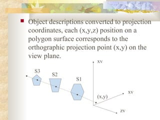
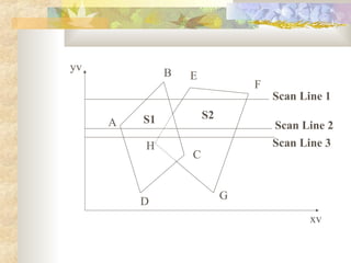

This document discusses methods for identifying and removing hidden surfaces when rendering 3D scenes to create a realistic 2D image. It describes two approaches: object-space methods that compare whole objects, and image-space methods that decide visibility point-by-point. It focuses on the depth buffer/z-buffer method, which processes surfaces one point at a time, comparing depth values to determine visibility and store the color of visible points. It also discusses using scan line coherence to solve hidden surfaces one scan line at a time from top to bottom.