Download to read offline

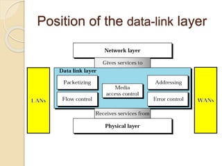
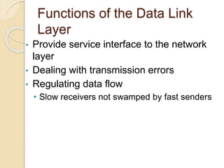
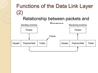
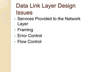
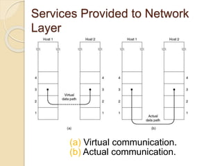
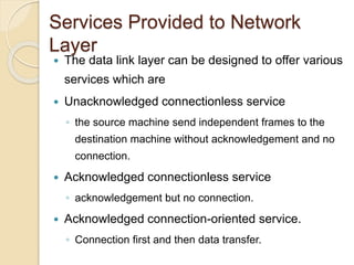
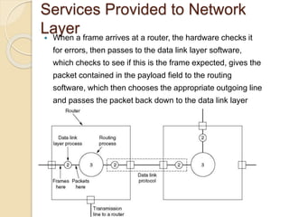
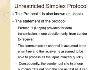
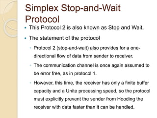
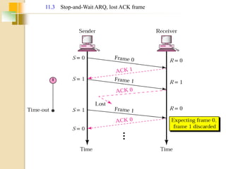
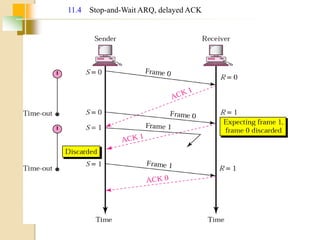
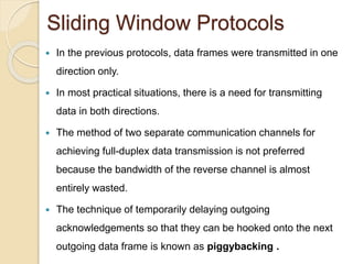
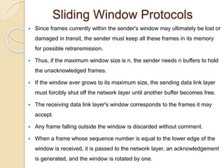
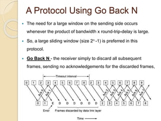
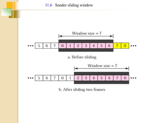
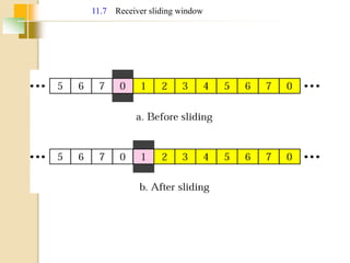
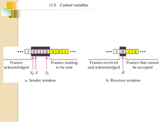
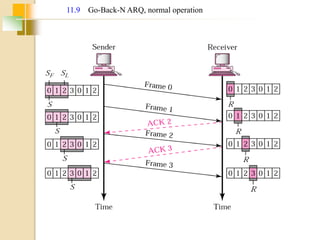
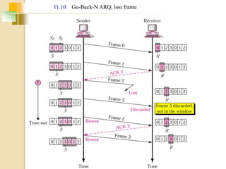
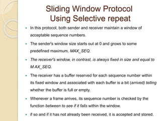
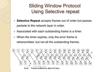
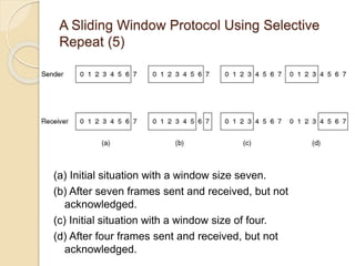

The document discusses various data link layer protocols. It begins by explaining the position and functions of the data link layer, including providing an interface to the network layer, dealing with transmission errors, regulating data flow, and preventing fast senders from overwhelming slow receivers. It then discusses various data link layer design issues like framing, error control, flow control, and the services provided to the network layer. The document proceeds to explain different elementary data link protocols like unrestricted simplex, stop-and-wait, and simplex protocols for noisy channels. It concludes by describing sliding window protocols including one-bit, go-back-N, and selective repeat protocols.


![Unit 2 [autosaved]](https://cdn.slidesharecdn.com/ss_thumbnails/unit-2autosaved-210914023404-thumbnail.jpg?width=640&height=640&fit=bounds)