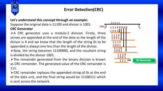
* Sushama Deshmukh 1
Course :
Computer Network (CSE 252)
Ms. Sushama Deshmukh
Assistant Professor in Computer Science & Engineering
Course Instructor
Unit III
Data Link Layer
⮚ Error Control, Flow Control, Error Detection and Correction,
⮚Error-Correcting Codes, Error-Detecting Codes.
⮚ Elementary Data Link Protocols
* 3
| Sushama Deshmukh
Index
⮚ Data Link Layer- Services Provided to the Network Layer, Framing,
⮚ Error Control, Flow Control, Error Detection and Correction, Error-Correcting
Codes, Error-Detecting Codes.
⮚ Elementary data link protocol, A Utopian Simplex Protocol,
⮚ A Simplex Stop-and-Wait Protocol for an Error-Free Channel, A Simplex Stop-and-
Wait Protocol for a Noisy Channel,
⮚ Sliding Window Protocols, A One-Bit Sliding Window Protocol,
⮚ A Protocol Using Go-Back-N, A Protocol Using Selective Repeat.
Error Control:
The error control function of the data link layer detects the errors in transmitted
frames and re-transmits all the erroneous frames.
Purpose of Error Control :
The function of error control function of the data link layer helps in dealing with
data frames that are damaged in transit, data frames lost in transit and
acknowledged frames that are lost in transmission.
The method used for error control is called Automatic Repeat Request (ARQ) which
is used for the noisy channel.
Example – Stop & Wait ARQ and Sliding Window ARQ
Error Control and Flow Control
Flow Control: It is an important function of the Data Link Layer. It refers to a set of
procedures that tells the sender how much data it can transmit before waiting for
acknowledgment from the receiver.
Purpose of Flow Control :
Any receiving device has a limited speed at which it can process incoming data and
also a limited amount of memory to store incoming data. If the source is sending the
data at a faster rate than the capacity of the receiver, there is a possibility of the
receiver being swamped. The receiver will keep losing some of the frames simply
because they are arriving too quickly and the buffer is also getting filled up.
This will generate waste frames on the network. Therefore, the receiving device must
have some mechanism to inform the sender to send fewer frames or stop
transmission temporarily. In this way, flow control will control the rate of frame
transmission to a value that can be handled by the receiver.
Example – Stop & Wait Protocol
Error Control and Flow Control
Error Detection
⮚ When data is transmitted from one device to another device, the system does not
guarantee whether the data received by the device is identical to the data transmitted by
another device.
⮚ An Error is a situation when the message received at the receiver end is not identical to
the message transmitted.
⮚Errors can be classified into two categories:
⮚Single-Bit Error
⮚Burst Error
Error Detection
In the above figure, the message which is sent is corrupted as single-bit, i.e., 0 bit is changed
to 1.
The only one bit of a given data unit is changed from 1 to 0 or from 0 to 1
Single-Bit Error:
Error Detection
Burst Error:
The two or more bits are changed from 0 to 1 or from 1 to 0 is known as Burst Error.
The Burst Error is determined from the first corrupted bit to the last corrupted bit.
⮚The duration of noise in Burst Error is more than the duration of noise in Single-Bit.
⮚Burst Errors are most likely to occur in Serial Data Transmission.
⮚The number of affected bits depends on the duration of the noise and data rate.
Error Detecting Techniques
The most popular Error Detecting Techniques are:
⮚Single/Simple parity check
⮚Two-dimensional parity check
⮚Checksum
⮚Cyclic Redundancy Check
Error Detection(Simple Parity Check)
1. Simple Parity check Blocks of data from the source are subjected to a check bit or parity bit
generator form, where a parity of :
1 is added to the block if it contains odd number of 1’s, and
0 is added if it contains even number of 1’s
This scheme makes the total number of 1’s even, that is why it is called even parity checking.
Single Parity check is not able to
detect even no. of bit error.
Error Detection(2D Parity Check)
2. Two-dimensional Parity check Parity check bits are calculated for each row, which is
equivalent to a simple parity check bit. Parity check bits are also calculated for all columns,
then both are sent along with the data. At the receiving end these are compared with the
parity bits calculated on the received data.
Error Detection(Checksum)
Checksum
A Checksum is an error detection technique based on the concept of redundancy.
It is divided into two parts:
•Checksum Generator
•Checksum Checker
Checksum Generator
A Checksum is generated at the sending side. Checksum generator subdivides the data into
equal segments of n bits each, and all these segments are added together by using one's
complement arithmetic. The sum is complemented and appended to the original data,
known as checksum field. The extended data is transmitted across the network.
https://www.youtube.com/watch?v=AtVWnyDDaDI
Error Detection(Checksum)
Checksum Generator
Suppose L is the total sum of the data segments, then the checksum would be ? L
Error Detection(Checksum)
⮚In checksum error detection scheme, the data is
divided into k segments each of m bits.
⮚In the sender’s end the segments are added using
1’s complement arithmetic to get the sum. The sum
is complemented to get the checksum.
⮚The checksum segment is sent along with the
data segments.
⮚At the receiver’s end, all received segments are
added using 1’s complement arithmetic to get the
sum. The sum is complemented.
⮚If the result is zero, the received data is accepted;
otherwise discarded.
Error Detection
The Sender follows the given steps:
The block unit is divided into k sections, and each of n bits.
All the k sections are added together by using one's complement to get the sum.
The sum is complemented and it becomes the checksum field.
The original data and checksum field are sent across the network.
Checksum Checker
A Checksum is verified at the receiving side. The receiver subdivides the incoming data into
equal segments of n bits each, and all these segments are added together, and then this sum
is complemented. If the complement of the sum is zero, then the data is accepted otherwise
data is rejected.
The Receiver follows the given steps:
The block unit is divided into k sections and each of n bits.
All the k sections are added together by using one's complement algorithm to get the sum.
The sum is complemented.
If the result of the sum is zero, then the data is accepted otherwise the data is discarded.
Error Detection (CRC)
Cyclic Redundancy Check (CRC):
CRC is a redundancy error technique used to determine the error.
Following are the steps used in CRC for error detection:
⮚In CRC technique, a string of n 0s is appended to the data unit, and this n number is less
than the number of bits in a predetermined number, known as division which is n+1 bits.
⮚Secondly, the newly extended data is divided by a divisor using a process is known as binary
division. The remainder generated from this division is known as CRC remainder.
⮚Thirdly, the CRC remainder replaces the appended 0s at the end of the original data. This
newly generated unit is sent to the receiver.
⮚The receiver receives the data followed by the CRC remainder. The receiver will treat this
whole unit as a single unit, and it is divided by the same divisor that was used to find the CRC
remainder.
Error Detection (CRC)
Cyclic Redundancy Check (CRC):
Error Detection (CRC)
Cyclic Redundancy Check (CRC):
Error Detection(CRC)
⮚If the resultant of this division is zero which
means that it has no error, and the data is
accepted.
⮚If the resultant of this division is not zero
which means that the data consists of an
error. Therefore, the data is discarded.
https://www.youtube.com/watch?v=A9g6rTMblz4 Part 1 (Sender)
https://www.youtube.com/watch?v=wQGwfBS3gpk Part 2 (Receiver)
Error Detection(CRC)
Let's understand this concept through an example:
Suppose the original data is 11100 and divisor is 1001.
CRC Generator
⮚A CRC generator uses a modulo-2 division. Firstly, three
zeroes are appended at the end of the data as the length of the
divisor is 4 and we know that the length of the string 0s to be
appended is always one less than the length of the divisor.
⮚Now, the string becomes 11100000, and the resultant string
is divided by the divisor 1001.
⮚The remainder generated from the binary division is known
as CRC remainder. The generated value of the CRC remainder is
111.
⮚CRC remainder replaces the appended string of 0s at the end
of the data unit, and the final string would be 11100111 which
is sent across the network.
Error Detection(CRC)
CRC Checker
⮚The functionality of the CRC checker is similar to
the CRC generator.
⮚When the string 11100111 is received at the
receiving end, then CRC checker performs the
modulo-2 division.
⮚A string is divided by the same divisor, i.e., 1001.
⮚In this case, CRC checker generates the remainder
of zero. Therefore, the data is accepted.
Error Correction
Error Correction
Error Correction codes are used to detect and correct the errors when data is transmitted
from the sender to the receiver.
Error Correction can be handled in two ways:
Backward error correction: Once the error is discovered, the receiver requests the sender to
retransmit the entire data unit.
Forward error correction: In this case, the receiver uses the error-correcting code which
automatically corrects the errors.
A single additional bit can detect the error, but cannot correct it.
For correcting the errors, one has to know the exact position of the error. For example, If
we want to calculate a single-bit error, the error correction code will determine which one of
seven bits is in error. To achieve this, we have to add some additional redundant bits.
Error Correction
https://www.youtube.com/watch?v=1A_NcXxdoCc Basics of Hamming Code
https://www.youtube.com/watch?v=wbH2VxzmoZk Error Correction
Hamming Code
Parity bits: The bit which is appended to the original data of binary bits so that the
total number of 1s is even or odd.
Even parity: To check for even parity, if the total number of 1s is even, then the
value of the parity bit is 0. If the total number of 1s occurrences is odd, then the
value of the parity bit is 1.
Odd Parity: To check for odd parity, if the total number of 1s is even, then the value
of parity bit is 1. If the total number of 1s is odd, then the value of parity bit is 0.
⮚https://www.geeksforgeeks.org/hamming-code-in-computer-network/?ref=lbp
Error Correction
Hamming Code
Hamming code is a block code that is capable of detecting up to two simultaneous bit errors
and correcting single-bit errors. It was developed by R.W. Hamming for error correction.
In this coding method, the source encodes the message by inserting redundant bits within
the message. These redundant bits are extra bits that are generated and inserted at specific
positions in the message itself to enable error detection and correction. When the
destination receives this message, it performs recalculations to detect errors and find the bit
position that has error.
Relationship b/w Error position & binary number.
https://www.youtube.com/watch?v=GmYOqxZlZUc
https://www.youtube.com/watch?v=9yWZM-9PKE8
* 26
| Sushama Deshmukh
Index
⮚ Data Link Layer- Services Provided to the Network Layer, Framing,
⮚ Error Control, Flow Control, Error Detection and Correction, Error-Correcting
Codes, Error-Detecting Codes.
⮚ Elementary data link protocol,
A Utopian Simplex Protocol,
A Simplex Stop-and-Wait Protocol for an Error-Free Channel,
A Simplex Stop-and-Wait Protocol for a Noisy Channel,
Sliding Window Protocols, A One-Bit Sliding Window Protocol,
A Protocol Using Go-Back-N, A Protocol Using Selective Repeat.
ELEMENTARY DATA LINK PROTOCOLS
To start with, we assume that the physical layer, data link layer, and network
layer are independent processes that communicate by passing messages back and
forth.
A common implementation is shown in Fig.
The physical layer process and some of the data link layer process run on dedicate
hardware called a NIC (Network Interface Card). The rest of the link layer process and
the network layer process run on the main CPU as part of the operating system, with
the software for the link layer process often taking the form of a device driver.
Protocols:
⮚A Utopian Simplex Protocol,
⮚A Simplex Stop-and-Wait Protocol for an Error-
Free Channel,
⮚A Simplex Stop-and-Wait Protocol for a Noisy
Channel
ELEMENTARY DATA LINK PROTOCOLS
Protocols:
⮚A Utopian Simplex Protocol,
⮚A Simplex Stop-and-Wait Protocol for an Error-Free Channel,
⮚A Simplex Stop-and-Wait Protocol for a Noisy Channel
ELEMENTARY DATA LINK PROTOCOLS
For Noiseless Channel
Utopian simplex Protocol
consider a protocol that is simply because it does not worry about the possibility of anything
going wrong. Data are transmitted in one direction only. Both transmitting and receiving
network layers are always ready. Processing time can be ignored. Infinite buffer space is
available. This thoroughly unrealistic protocol, which we will nickname “Utopia”, is simply to
show the basic structure on which we will build. Its implementation is shown below.
Utopian simplex Protocol: There is one direction of data transmission only from sender to
receiver. Here we assume the communication channel to be error-free and the receiver will
infinitely quickly process the input. The sender pumps out the data onto the line as fast as it
can.
ELEMENTARY DATA LINK PROTOCOLS
For Noiseless Channel
⮚Properties of Utopian Simplex Protocol:
⮚The design of Utopian Simplex Protocol is based on 2 procedures i.e. Sender and
Receiver.
⮚Both Sender and Receiver run in the data link layer but the sender runs in the data link
layer of the source machine while Receiver runs in datalink layer of the destination
machine.
⮚It is designed for Uni-directional data transmission.
⮚Sender and receiver are always ready for data processing.
⮚Both of them have infinite buffer space available.
⮚The communication links never losses any data frames.
⮚It is considered as unrealistic as it does not handle flow control or error correction.
ELEMENTARY DATA LINK PROTOCOLS
For Noiseless Channel
A Simplex Stop-and-Wait Protocol for an Error-Free Channel:
⮚Stop and wait means ?
- A flow control protocol
- a data-link layer protocol which is used for transmitting the data over the
noiseless channels.
- It provides unidirectional data transmission
- It does not provide any error control mechanism.
ELEMENTARY DATA LINK PROTOCOLS
For Noiseless Channel
A Simplex Stop-and-Wait Protocol for an Error-Free Channel:
The primitives of stop and wait protocol are:
Sender side
Rule 1: Sender sends one data packet at a time.
Rule2: Sender sends the next packet only when it receives the
acknowledgment of the previous packet.
Therefore, the idea of stop and wait protocol in the sender's side is
very simple, i.e., send one packet at a time, and do not send
another packet before receiving the acknowledgment.
Receiver side
Rule1: Receive and then consume the data packet.
Rule2: When the data packet is consumed, receiver sends the
acknowledgment to the sender.
Therefore, the idea of stop and wait protocol in the receiver's side is
also very simple, i.e., consume the packet, and once the packet is
consumed, the acknowledgment is sent. This is known as a flow
control mechanism.
ELEMENTARY DATA LINK PROTOCOLS
For Noiseless Channel
A Simplex Stop-and-Wait Protocol for an Error-Free Channel
Working
The figure shows the working of the stop and wait protocol. If
there is a sender and receiver, then sender sends the packet
and that packet is known as a data packet. The sender will not
send the second packet without receiving the
acknowledgment of the first packet. The receiver sends the
acknowledgment for the data packet that it has received.
Once the acknowledgment is received, the sender sends the
next packet. This process continues until all the packet are not
sent. The main advantage of this protocol is its simplicity but it
has some disadvantages also.
For example, if there are 1000 data packets to be sent, then
all the 1000 packets cannot be sent at a time as in Stop and
Wait protocol, one packet is sent at a time.
ELEMENTARY DATA LINK PROTOCOLS
Noisy Channel protocols
⮚is a type of communication protocol that is used in communication systems where the
transmission channel may introduce errors into the transmitted data.
⮚This type of protocol is designed to deal with errors in the communication channel and
ensure that the data being transmitted is received accurately at the receiver end.
⮚ The main objective of Noisy Channel Protocols is to minimize the error rate in the
transmitted data by using techniques such as error detection and correction, flow control,
and retransmission of lost or corrupted data frames.
⮚Some examples of Noisy Channel Protocols include, 1) Stop-and-Wait ARQ Protocol, The
sliding window is further divided into two categories, i.e., 2) Go Back N-ARQ, and 3)
Selective Repeat and Automatic Repeat Request (ARQ) Protocol.
⮚Based on the usage, the people select the error control mechanism whether it is stop and
wait or sliding window.
For Noisy Channel
ELEMENTARY DATA LINK PROTOCOLS
1. Stop-and-Wait ARQ Protocol
⮚used for reliable data transmission over a noisy channel
⮚The sender only sends one frame at a time and waits for an acknowledgment (ACK)
from the receiver before sending the next frame. This helps to ensure that the
receiver receives the data correctly and eliminates the need for retransmission in the
case of errors caused by the noisy channel.
⮚The sender continuously monitors the channel for errors, and if an error is
detected, it waits for the next ACK before resending the frame.
⮚This protocol adds error control to the basic unidirectional communication of data
frames and ACK frames in the opposite direction.
For Noisy Channel
ELEMENTARY DATA LINK PROTOCOLS
Stop-and-Wait ARQ Protocol Flow Diagram
Sender: The sender sends data frames one at a time, and
waits for a response (ACK or NACK) from the receiver before
sending the next data frame.
Receiver: The receiver receives the data frames and processes
them. If the frame is received correctly, the receiver sends an
ACK signal to the sender. If the frame is not received
correctly, the receiver sends a NACK signal to the sender.
Noisy Channel: The noisy channel is the medium through
which the data frames are transmitted from the sender to
the receiver. The channel can add noise to the data frames,
resulting in errors and corruption of the data.
Error Detection: The receiver uses error detection techniques
such as checksums to detect errors in the received data
frames. Error Correction: If an error is detected, the receiver
sends a NACK signal to the sender, requesting a
retransmission of the frame.
For Noisy Channel
For Noisy Channel
ELEMENTARY DATA LINK
PROTOCOLS
2. GO-BACK-N ARQ Protocol -
⮚The Go-Back-N Automatic Repeat Request (ARQ) protocol is a type of error-control
protocol used in data communication to ensure reliable delivery of data over a noisy
channel.
⮚In a noisy channel, the probability of errors in the received packets is high, and hence,
there is a need for a mechanism to detect and correct these errors.
⮚The Go-Back-N ARQ protocol is a type of sliding window protocol where the sender
transmits a window of packets to the receiver, and the receiver sends back an
acknowledgment (ACK) to the sender indicating successful receipt of the packets.
⮚ In case the sender does not receive an ACK within a specified timeout period, it
retransmits the entire window of packets.
For Noisy Channel
ELEMENTARY DATA LINK
PROTOCOLS
The flow diagram that illustrates the operation of the Go-Back-N ARQ
protocol in a noisy channel:
Sender Side:
•The sender transmits a window of packets to the receiver,
starting with sequence number i and ending with sequence
number i + N - 1, where N is the window size.
•The sender sets a timer for each packet in the window.
•The sender waits for an acknowledgment (ACK) from the
receiver.
•Receiver Side: The receiver receives the packets and checks
for errors.
•If a packet is received correctly, the receiver sends an ACK
back to the sender with the sequence number of the next
expected packet.
•If a packet is received with errors, the receiver discards the
packet and sends a negative acknowledgment (NAK) to the
sender with the sequence number of the next expected
packet.
GO-BACK-N ARQ Protocol
For Noisy Channel
ELEMENTARY DATA LINK
PROTOCOLS
Sender Side (in case of no ACK received):
•If the sender does not receive an ACK before the timer for a packet expires, the sender
retransmits the entire window of packets starting with the packet whose timer expired.
•The sender resets the timer for each packet in the window.
•The sender waits for an ACK from the receiver.
Sender Side (in case of NAK received):
•If the sender receives a NAK from the receiver, the sender retransmits only the packets that
were not correctly received by the receiver.
•The sender resets the timer for each packet that was retransmitted.
•The sender waits for an ACK from the receiver.
•The above steps are repeated until all packets have been successfully received by the
receiver. The Go-Back-N ARQ protocol provides a reliable mechanism for transmitting data
over a noisy channel while minimizing the number of retransmissions required.
2. GO-BACK-N ARQ Protocol continued…..
For Noisy Channel
ELEMENTARY DATA LINK
PROTOCOLS
⮚ Working: SRARQ Protocol a type of error-control protocol used in data communication to
ensure reliable delivery of data over a noisy channel.
⮚ Unlike the Go-Back-N ARQ protocol which retransmits the entire window of packets, the
Selective Repeat ARQ protocol retransmits only the packets that were not correctly received.
⮚ In this protocol, the sender transmits a window of packets to the receiver, and the receiver
sends back an acknowledgment (ACK) to the sender indicating successful receipt of the packets.
If the receiver detects an error in a packet, it sends a negative acknowledgment (NAK) to the
sender requesting retransmission of that packet.
⮚ The sender maintains a timer for each packet in the window. If the sender does not receive
an ACK for a packet before its timer expires, the sender retransmits only that packet.
⮚ At the receiver side, if a packet is received correctly, the receiver sends back an ACK with the
sequence number of the next expected packet. However, if a packet is received with errors, the
receiver discards the packet and sends back a NAK with the sequence number of the packet that
needs to be retransmitted.
3. SELECTIVE REPEAT ARQ Protocol
For Noisy Channel
ELEMENTARY DATA LINK
PROTOCOLS
⮚Unlike Go-Back-N ARQ, in Selective Repeat ARQ, the receiver buffer is maintained for all
packets that are not in sequence. When a packet with a sequence number different from
the expected sequence number arrives at the receiver, it is buffered, and the receiver sends
an ACK for the last in-order packet it has received.
⮚If a packet with a sequence number that the receiver has already buffered arrives, it is
discarded, and the receiver sends an ACK for the last in-order packet it has received.
⮚In summary, the Selective Repeat ARQ protocol provides a reliable mechanism for
transmitting data over a noisy channel while minimizing the number of retransmissions
required.
It retransmits only the packets that were not correctly received and buffers packets that
arrive out of order to reduce the number of retransmissions required.
3. SELECTIVE REPEAT ARQ Protocol continued……
For Noisy Channel
ELEMENTARY DATA LINK
PROTOCOLS
3. SELECTIVE REPEAT ARQ Protocol continued……
Flow Diagram
The flow diagram that illustrates the operation of the Selective Repeat ARQ protocol in a noisy channel:
For Noisy Channel
ELEMENTARY DATA LINK
PROTOCOLS
3. SELECTIVE REPEAT ARQ Protocol continued……
Sender Side:
⮚The sender transmits a window of packets to the receiver, starting with sequence number i
and ending with sequence number i + N - 1, where N is the window size.
⮚The sender sets a timer for each packet in the window.
⮚The sender waits for an acknowledgment (ACK) from the receiver.
Receiver Side:
⮚The receiver receives the packets and checks for errors.
⮚If a packet is received correctly and is in order, the receiver sends an ACK back to the sender
with the sequence number of the next expected packet.
⮚If a packet is received with errors or is out of order, the receiver discards the packet and
sends a negative acknowledgment (NAK) to the sender with the sequence number of the
packet that needs to be retransmitted.
⮚The receiver buffers out-of-order packets and sends an ACK for the last in-order packet it
has received.
For Noisy Channel
ELEMENTARY DATA LINK
PROTOCOLS
3. SELECTIVE REPEAT ARQ Protocol continued……
Sender Side (in case of no ACK received):
⮚If the sender does not receive an ACK before the timer for a packet expires, the sender
retransmits only that packet.
⮚The sender resets the timer for the retransmitted packet.
⮚The sender waits for an ACK from the receiver.
Sender Side (in case of NAK received):
⮚If the sender receives a NAK from the receiver, the sender retransmits only the packets that
were not correctly received.
⮚The sender resets the timer for each packet that was retransmitted.
⮚The sender waits for an ACK from the receiver.
⮚The above steps are repeated until all packets have been successfully received by the receiver.
The Selective Repeat ARQ protocol provides a reliable mechanism for transmitting data over a
noisy channel while minimizing the number of retransmissions required. It retransmits only the
packets that were not correctly received, and buffers out-of-order packets to reduce the number
of retransmissions required.
Conclusion
A. Stop-and-Wait ARQ:
⮚The simplest of the three protocols.
⮚The sender transmits one packet at a time and waits for an acknowledgment (ACK)
from the receiver before sending the next packet.
⮚If the ACK is not received within a certain time, the sender retransmits the packet.
⮚Suitable for channels with low error rates, low data rates, and short transmission
distances.
B. Go-Back-N ARQ:
⮚The sender transmits a window of packets to the receiver.
⮚If the receiver detects an error in a packet, it sends a negative acknowledgment
(NAK) to the sender requesting retransmission of that packet, as well as all subsequent
packets in the window.
⮚The sender retransmits the entire window of packets that were not correctly
received.
⮚Suitable for channels with moderate to high error rates and moderate data rates.
Conclusion
C. Selective Repeat ARQ:
⮚The sender transmits a window of packets to the receiver.
⮚If the receiver detects an error in a packet, it sends a NAK to the sender requesting
retransmission of that packet only.
⮚The sender retransmits only the packets that were not correctly received.
⮚The receiver buffers out-of-order packets to reduce the number of retransmissions
required.
⮚Suitable for channels with moderate to high error rates, high data rates, and long
transmission distances.
D. Summary:
⮚Stop-and-Wait ARQ is the simplest and most reliable protocol but not suitable for high data
rates.
⮚Go-Back-N ARQ is suitable for channels with moderate to high error rates, and Selective
Repeat ARQ is suitable for high data rates and long transmission distances.
⮚The choice of protocol depends on the characteristics of the communication channel and
the requirements of the application.
* © Copyright | Sushama Deshmukh 47
Web References
• https://www.geeksforgeeks.org/error-detection-in-computer-networks/
• https://www.javatpoint.com/computer-network-error-detection
• https://www.javatpoint.com/protocols-in-noiseless-and-noisy-channel
• GATE questions based on error detection: GATE CS 2009 Question 48 GATE CS 2007 Question 68
• https://www.youtube.com/watch?v=n09DfvemnTQ
• https://www.youtube.com/watch?v=YdkksvhkQGQ
• Stop & Wait Protocol: https://www.youtube.com/watch?v=n09DfvemnTQ
• Stop & Wait ARQ : https://www.youtube.com/watch?v=YdkksvhkQGQ
• Sliding Window Protocol: https://www.youtube.com/watch?v=LnbvhoxHn8M
• Go – Back-N-ARQ : https://www.youtube.com/watch?v=QD3oCelHJ20&t=29s
• Selective Repeat ARQ : https://www.youtube.com/watch?v=WfIhQ3o2xow
48
Thank You
* © Copyright | Sushama Deshmukh

III_UNIT_ErrorCorrecting.pptx

  • 1.
    * Sushama Deshmukh1 Course : Computer Network (CSE 252) Ms. Sushama Deshmukh Assistant Professor in Computer Science & Engineering Course Instructor
  • 2.
    Unit III Data LinkLayer ⮚ Error Control, Flow Control, Error Detection and Correction, ⮚Error-Correcting Codes, Error-Detecting Codes. ⮚ Elementary Data Link Protocols
  • 3.
    * 3 | SushamaDeshmukh Index ⮚ Data Link Layer- Services Provided to the Network Layer, Framing, ⮚ Error Control, Flow Control, Error Detection and Correction, Error-Correcting Codes, Error-Detecting Codes. ⮚ Elementary data link protocol, A Utopian Simplex Protocol, ⮚ A Simplex Stop-and-Wait Protocol for an Error-Free Channel, A Simplex Stop-and- Wait Protocol for a Noisy Channel, ⮚ Sliding Window Protocols, A One-Bit Sliding Window Protocol, ⮚ A Protocol Using Go-Back-N, A Protocol Using Selective Repeat.
  • 4.
    Error Control: The errorcontrol function of the data link layer detects the errors in transmitted frames and re-transmits all the erroneous frames. Purpose of Error Control : The function of error control function of the data link layer helps in dealing with data frames that are damaged in transit, data frames lost in transit and acknowledged frames that are lost in transmission. The method used for error control is called Automatic Repeat Request (ARQ) which is used for the noisy channel. Example – Stop & Wait ARQ and Sliding Window ARQ Error Control and Flow Control
  • 5.
    Flow Control: Itis an important function of the Data Link Layer. It refers to a set of procedures that tells the sender how much data it can transmit before waiting for acknowledgment from the receiver. Purpose of Flow Control : Any receiving device has a limited speed at which it can process incoming data and also a limited amount of memory to store incoming data. If the source is sending the data at a faster rate than the capacity of the receiver, there is a possibility of the receiver being swamped. The receiver will keep losing some of the frames simply because they are arriving too quickly and the buffer is also getting filled up. This will generate waste frames on the network. Therefore, the receiving device must have some mechanism to inform the sender to send fewer frames or stop transmission temporarily. In this way, flow control will control the rate of frame transmission to a value that can be handled by the receiver. Example – Stop & Wait Protocol Error Control and Flow Control
  • 6.
    Error Detection ⮚ Whendata is transmitted from one device to another device, the system does not guarantee whether the data received by the device is identical to the data transmitted by another device. ⮚ An Error is a situation when the message received at the receiver end is not identical to the message transmitted. ⮚Errors can be classified into two categories: ⮚Single-Bit Error ⮚Burst Error
  • 7.
    Error Detection In theabove figure, the message which is sent is corrupted as single-bit, i.e., 0 bit is changed to 1. The only one bit of a given data unit is changed from 1 to 0 or from 0 to 1 Single-Bit Error:
  • 8.
    Error Detection Burst Error: Thetwo or more bits are changed from 0 to 1 or from 1 to 0 is known as Burst Error. The Burst Error is determined from the first corrupted bit to the last corrupted bit. ⮚The duration of noise in Burst Error is more than the duration of noise in Single-Bit. ⮚Burst Errors are most likely to occur in Serial Data Transmission. ⮚The number of affected bits depends on the duration of the noise and data rate.
  • 9.
    Error Detecting Techniques Themost popular Error Detecting Techniques are: ⮚Single/Simple parity check ⮚Two-dimensional parity check ⮚Checksum ⮚Cyclic Redundancy Check
  • 10.
    Error Detection(Simple ParityCheck) 1. Simple Parity check Blocks of data from the source are subjected to a check bit or parity bit generator form, where a parity of : 1 is added to the block if it contains odd number of 1’s, and 0 is added if it contains even number of 1’s This scheme makes the total number of 1’s even, that is why it is called even parity checking. Single Parity check is not able to detect even no. of bit error.
  • 11.
    Error Detection(2D ParityCheck) 2. Two-dimensional Parity check Parity check bits are calculated for each row, which is equivalent to a simple parity check bit. Parity check bits are also calculated for all columns, then both are sent along with the data. At the receiving end these are compared with the parity bits calculated on the received data.
  • 12.
    Error Detection(Checksum) Checksum A Checksumis an error detection technique based on the concept of redundancy. It is divided into two parts: •Checksum Generator •Checksum Checker Checksum Generator A Checksum is generated at the sending side. Checksum generator subdivides the data into equal segments of n bits each, and all these segments are added together by using one's complement arithmetic. The sum is complemented and appended to the original data, known as checksum field. The extended data is transmitted across the network. https://www.youtube.com/watch?v=AtVWnyDDaDI
  • 13.
    Error Detection(Checksum) Checksum Generator SupposeL is the total sum of the data segments, then the checksum would be ? L
  • 14.
    Error Detection(Checksum) ⮚In checksumerror detection scheme, the data is divided into k segments each of m bits. ⮚In the sender’s end the segments are added using 1’s complement arithmetic to get the sum. The sum is complemented to get the checksum. ⮚The checksum segment is sent along with the data segments. ⮚At the receiver’s end, all received segments are added using 1’s complement arithmetic to get the sum. The sum is complemented. ⮚If the result is zero, the received data is accepted; otherwise discarded.
  • 15.
    Error Detection The Senderfollows the given steps: The block unit is divided into k sections, and each of n bits. All the k sections are added together by using one's complement to get the sum. The sum is complemented and it becomes the checksum field. The original data and checksum field are sent across the network. Checksum Checker A Checksum is verified at the receiving side. The receiver subdivides the incoming data into equal segments of n bits each, and all these segments are added together, and then this sum is complemented. If the complement of the sum is zero, then the data is accepted otherwise data is rejected. The Receiver follows the given steps: The block unit is divided into k sections and each of n bits. All the k sections are added together by using one's complement algorithm to get the sum. The sum is complemented. If the result of the sum is zero, then the data is accepted otherwise the data is discarded.
  • 16.
    Error Detection (CRC) CyclicRedundancy Check (CRC): CRC is a redundancy error technique used to determine the error. Following are the steps used in CRC for error detection: ⮚In CRC technique, a string of n 0s is appended to the data unit, and this n number is less than the number of bits in a predetermined number, known as division which is n+1 bits. ⮚Secondly, the newly extended data is divided by a divisor using a process is known as binary division. The remainder generated from this division is known as CRC remainder. ⮚Thirdly, the CRC remainder replaces the appended 0s at the end of the original data. This newly generated unit is sent to the receiver. ⮚The receiver receives the data followed by the CRC remainder. The receiver will treat this whole unit as a single unit, and it is divided by the same divisor that was used to find the CRC remainder.
  • 17.
    Error Detection (CRC) CyclicRedundancy Check (CRC):
  • 18.
    Error Detection (CRC) CyclicRedundancy Check (CRC):
  • 19.
    Error Detection(CRC) ⮚If theresultant of this division is zero which means that it has no error, and the data is accepted. ⮚If the resultant of this division is not zero which means that the data consists of an error. Therefore, the data is discarded. https://www.youtube.com/watch?v=A9g6rTMblz4 Part 1 (Sender) https://www.youtube.com/watch?v=wQGwfBS3gpk Part 2 (Receiver)
  • 20.
    Error Detection(CRC) Let's understandthis concept through an example: Suppose the original data is 11100 and divisor is 1001. CRC Generator ⮚A CRC generator uses a modulo-2 division. Firstly, three zeroes are appended at the end of the data as the length of the divisor is 4 and we know that the length of the string 0s to be appended is always one less than the length of the divisor. ⮚Now, the string becomes 11100000, and the resultant string is divided by the divisor 1001. ⮚The remainder generated from the binary division is known as CRC remainder. The generated value of the CRC remainder is 111. ⮚CRC remainder replaces the appended string of 0s at the end of the data unit, and the final string would be 11100111 which is sent across the network.
  • 21.
    Error Detection(CRC) CRC Checker ⮚Thefunctionality of the CRC checker is similar to the CRC generator. ⮚When the string 11100111 is received at the receiving end, then CRC checker performs the modulo-2 division. ⮚A string is divided by the same divisor, i.e., 1001. ⮚In this case, CRC checker generates the remainder of zero. Therefore, the data is accepted.
  • 22.
    Error Correction Error Correction ErrorCorrection codes are used to detect and correct the errors when data is transmitted from the sender to the receiver. Error Correction can be handled in two ways: Backward error correction: Once the error is discovered, the receiver requests the sender to retransmit the entire data unit. Forward error correction: In this case, the receiver uses the error-correcting code which automatically corrects the errors. A single additional bit can detect the error, but cannot correct it. For correcting the errors, one has to know the exact position of the error. For example, If we want to calculate a single-bit error, the error correction code will determine which one of seven bits is in error. To achieve this, we have to add some additional redundant bits.
  • 23.
    Error Correction https://www.youtube.com/watch?v=1A_NcXxdoCc Basicsof Hamming Code https://www.youtube.com/watch?v=wbH2VxzmoZk Error Correction Hamming Code Parity bits: The bit which is appended to the original data of binary bits so that the total number of 1s is even or odd. Even parity: To check for even parity, if the total number of 1s is even, then the value of the parity bit is 0. If the total number of 1s occurrences is odd, then the value of the parity bit is 1. Odd Parity: To check for odd parity, if the total number of 1s is even, then the value of parity bit is 1. If the total number of 1s is odd, then the value of parity bit is 0. ⮚https://www.geeksforgeeks.org/hamming-code-in-computer-network/?ref=lbp
  • 24.
    Error Correction Hamming Code Hammingcode is a block code that is capable of detecting up to two simultaneous bit errors and correcting single-bit errors. It was developed by R.W. Hamming for error correction. In this coding method, the source encodes the message by inserting redundant bits within the message. These redundant bits are extra bits that are generated and inserted at specific positions in the message itself to enable error detection and correction. When the destination receives this message, it performs recalculations to detect errors and find the bit position that has error. Relationship b/w Error position & binary number. https://www.youtube.com/watch?v=GmYOqxZlZUc https://www.youtube.com/watch?v=9yWZM-9PKE8
  • 25.
    * 26 | SushamaDeshmukh Index ⮚ Data Link Layer- Services Provided to the Network Layer, Framing, ⮚ Error Control, Flow Control, Error Detection and Correction, Error-Correcting Codes, Error-Detecting Codes. ⮚ Elementary data link protocol, A Utopian Simplex Protocol, A Simplex Stop-and-Wait Protocol for an Error-Free Channel, A Simplex Stop-and-Wait Protocol for a Noisy Channel, Sliding Window Protocols, A One-Bit Sliding Window Protocol, A Protocol Using Go-Back-N, A Protocol Using Selective Repeat.
  • 26.
    ELEMENTARY DATA LINKPROTOCOLS To start with, we assume that the physical layer, data link layer, and network layer are independent processes that communicate by passing messages back and forth. A common implementation is shown in Fig. The physical layer process and some of the data link layer process run on dedicate hardware called a NIC (Network Interface Card). The rest of the link layer process and the network layer process run on the main CPU as part of the operating system, with the software for the link layer process often taking the form of a device driver. Protocols: ⮚A Utopian Simplex Protocol, ⮚A Simplex Stop-and-Wait Protocol for an Error- Free Channel, ⮚A Simplex Stop-and-Wait Protocol for a Noisy Channel
  • 27.
    ELEMENTARY DATA LINKPROTOCOLS Protocols: ⮚A Utopian Simplex Protocol, ⮚A Simplex Stop-and-Wait Protocol for an Error-Free Channel, ⮚A Simplex Stop-and-Wait Protocol for a Noisy Channel
  • 28.
    ELEMENTARY DATA LINKPROTOCOLS For Noiseless Channel Utopian simplex Protocol consider a protocol that is simply because it does not worry about the possibility of anything going wrong. Data are transmitted in one direction only. Both transmitting and receiving network layers are always ready. Processing time can be ignored. Infinite buffer space is available. This thoroughly unrealistic protocol, which we will nickname “Utopia”, is simply to show the basic structure on which we will build. Its implementation is shown below. Utopian simplex Protocol: There is one direction of data transmission only from sender to receiver. Here we assume the communication channel to be error-free and the receiver will infinitely quickly process the input. The sender pumps out the data onto the line as fast as it can.
  • 29.
    ELEMENTARY DATA LINKPROTOCOLS For Noiseless Channel ⮚Properties of Utopian Simplex Protocol: ⮚The design of Utopian Simplex Protocol is based on 2 procedures i.e. Sender and Receiver. ⮚Both Sender and Receiver run in the data link layer but the sender runs in the data link layer of the source machine while Receiver runs in datalink layer of the destination machine. ⮚It is designed for Uni-directional data transmission. ⮚Sender and receiver are always ready for data processing. ⮚Both of them have infinite buffer space available. ⮚The communication links never losses any data frames. ⮚It is considered as unrealistic as it does not handle flow control or error correction.
  • 30.
    ELEMENTARY DATA LINKPROTOCOLS For Noiseless Channel A Simplex Stop-and-Wait Protocol for an Error-Free Channel: ⮚Stop and wait means ? - A flow control protocol - a data-link layer protocol which is used for transmitting the data over the noiseless channels. - It provides unidirectional data transmission - It does not provide any error control mechanism.
  • 31.
    ELEMENTARY DATA LINKPROTOCOLS For Noiseless Channel A Simplex Stop-and-Wait Protocol for an Error-Free Channel: The primitives of stop and wait protocol are: Sender side Rule 1: Sender sends one data packet at a time. Rule2: Sender sends the next packet only when it receives the acknowledgment of the previous packet. Therefore, the idea of stop and wait protocol in the sender's side is very simple, i.e., send one packet at a time, and do not send another packet before receiving the acknowledgment. Receiver side Rule1: Receive and then consume the data packet. Rule2: When the data packet is consumed, receiver sends the acknowledgment to the sender. Therefore, the idea of stop and wait protocol in the receiver's side is also very simple, i.e., consume the packet, and once the packet is consumed, the acknowledgment is sent. This is known as a flow control mechanism.
  • 32.
    ELEMENTARY DATA LINKPROTOCOLS For Noiseless Channel A Simplex Stop-and-Wait Protocol for an Error-Free Channel Working The figure shows the working of the stop and wait protocol. If there is a sender and receiver, then sender sends the packet and that packet is known as a data packet. The sender will not send the second packet without receiving the acknowledgment of the first packet. The receiver sends the acknowledgment for the data packet that it has received. Once the acknowledgment is received, the sender sends the next packet. This process continues until all the packet are not sent. The main advantage of this protocol is its simplicity but it has some disadvantages also. For example, if there are 1000 data packets to be sent, then all the 1000 packets cannot be sent at a time as in Stop and Wait protocol, one packet is sent at a time.
  • 33.
    ELEMENTARY DATA LINKPROTOCOLS Noisy Channel protocols ⮚is a type of communication protocol that is used in communication systems where the transmission channel may introduce errors into the transmitted data. ⮚This type of protocol is designed to deal with errors in the communication channel and ensure that the data being transmitted is received accurately at the receiver end. ⮚ The main objective of Noisy Channel Protocols is to minimize the error rate in the transmitted data by using techniques such as error detection and correction, flow control, and retransmission of lost or corrupted data frames. ⮚Some examples of Noisy Channel Protocols include, 1) Stop-and-Wait ARQ Protocol, The sliding window is further divided into two categories, i.e., 2) Go Back N-ARQ, and 3) Selective Repeat and Automatic Repeat Request (ARQ) Protocol. ⮚Based on the usage, the people select the error control mechanism whether it is stop and wait or sliding window. For Noisy Channel
  • 34.
    ELEMENTARY DATA LINKPROTOCOLS 1. Stop-and-Wait ARQ Protocol ⮚used for reliable data transmission over a noisy channel ⮚The sender only sends one frame at a time and waits for an acknowledgment (ACK) from the receiver before sending the next frame. This helps to ensure that the receiver receives the data correctly and eliminates the need for retransmission in the case of errors caused by the noisy channel. ⮚The sender continuously monitors the channel for errors, and if an error is detected, it waits for the next ACK before resending the frame. ⮚This protocol adds error control to the basic unidirectional communication of data frames and ACK frames in the opposite direction. For Noisy Channel
  • 35.
    ELEMENTARY DATA LINKPROTOCOLS Stop-and-Wait ARQ Protocol Flow Diagram Sender: The sender sends data frames one at a time, and waits for a response (ACK or NACK) from the receiver before sending the next data frame. Receiver: The receiver receives the data frames and processes them. If the frame is received correctly, the receiver sends an ACK signal to the sender. If the frame is not received correctly, the receiver sends a NACK signal to the sender. Noisy Channel: The noisy channel is the medium through which the data frames are transmitted from the sender to the receiver. The channel can add noise to the data frames, resulting in errors and corruption of the data. Error Detection: The receiver uses error detection techniques such as checksums to detect errors in the received data frames. Error Correction: If an error is detected, the receiver sends a NACK signal to the sender, requesting a retransmission of the frame. For Noisy Channel
  • 36.
    For Noisy Channel ELEMENTARYDATA LINK PROTOCOLS 2. GO-BACK-N ARQ Protocol - ⮚The Go-Back-N Automatic Repeat Request (ARQ) protocol is a type of error-control protocol used in data communication to ensure reliable delivery of data over a noisy channel. ⮚In a noisy channel, the probability of errors in the received packets is high, and hence, there is a need for a mechanism to detect and correct these errors. ⮚The Go-Back-N ARQ protocol is a type of sliding window protocol where the sender transmits a window of packets to the receiver, and the receiver sends back an acknowledgment (ACK) to the sender indicating successful receipt of the packets. ⮚ In case the sender does not receive an ACK within a specified timeout period, it retransmits the entire window of packets.
  • 37.
    For Noisy Channel ELEMENTARYDATA LINK PROTOCOLS The flow diagram that illustrates the operation of the Go-Back-N ARQ protocol in a noisy channel: Sender Side: •The sender transmits a window of packets to the receiver, starting with sequence number i and ending with sequence number i + N - 1, where N is the window size. •The sender sets a timer for each packet in the window. •The sender waits for an acknowledgment (ACK) from the receiver. •Receiver Side: The receiver receives the packets and checks for errors. •If a packet is received correctly, the receiver sends an ACK back to the sender with the sequence number of the next expected packet. •If a packet is received with errors, the receiver discards the packet and sends a negative acknowledgment (NAK) to the sender with the sequence number of the next expected packet. GO-BACK-N ARQ Protocol
  • 38.
    For Noisy Channel ELEMENTARYDATA LINK PROTOCOLS Sender Side (in case of no ACK received): •If the sender does not receive an ACK before the timer for a packet expires, the sender retransmits the entire window of packets starting with the packet whose timer expired. •The sender resets the timer for each packet in the window. •The sender waits for an ACK from the receiver. Sender Side (in case of NAK received): •If the sender receives a NAK from the receiver, the sender retransmits only the packets that were not correctly received by the receiver. •The sender resets the timer for each packet that was retransmitted. •The sender waits for an ACK from the receiver. •The above steps are repeated until all packets have been successfully received by the receiver. The Go-Back-N ARQ protocol provides a reliable mechanism for transmitting data over a noisy channel while minimizing the number of retransmissions required. 2. GO-BACK-N ARQ Protocol continued…..
  • 39.
    For Noisy Channel ELEMENTARYDATA LINK PROTOCOLS ⮚ Working: SRARQ Protocol a type of error-control protocol used in data communication to ensure reliable delivery of data over a noisy channel. ⮚ Unlike the Go-Back-N ARQ protocol which retransmits the entire window of packets, the Selective Repeat ARQ protocol retransmits only the packets that were not correctly received. ⮚ In this protocol, the sender transmits a window of packets to the receiver, and the receiver sends back an acknowledgment (ACK) to the sender indicating successful receipt of the packets. If the receiver detects an error in a packet, it sends a negative acknowledgment (NAK) to the sender requesting retransmission of that packet. ⮚ The sender maintains a timer for each packet in the window. If the sender does not receive an ACK for a packet before its timer expires, the sender retransmits only that packet. ⮚ At the receiver side, if a packet is received correctly, the receiver sends back an ACK with the sequence number of the next expected packet. However, if a packet is received with errors, the receiver discards the packet and sends back a NAK with the sequence number of the packet that needs to be retransmitted. 3. SELECTIVE REPEAT ARQ Protocol
  • 40.
    For Noisy Channel ELEMENTARYDATA LINK PROTOCOLS ⮚Unlike Go-Back-N ARQ, in Selective Repeat ARQ, the receiver buffer is maintained for all packets that are not in sequence. When a packet with a sequence number different from the expected sequence number arrives at the receiver, it is buffered, and the receiver sends an ACK for the last in-order packet it has received. ⮚If a packet with a sequence number that the receiver has already buffered arrives, it is discarded, and the receiver sends an ACK for the last in-order packet it has received. ⮚In summary, the Selective Repeat ARQ protocol provides a reliable mechanism for transmitting data over a noisy channel while minimizing the number of retransmissions required. It retransmits only the packets that were not correctly received and buffers packets that arrive out of order to reduce the number of retransmissions required. 3. SELECTIVE REPEAT ARQ Protocol continued……
  • 41.
    For Noisy Channel ELEMENTARYDATA LINK PROTOCOLS 3. SELECTIVE REPEAT ARQ Protocol continued…… Flow Diagram The flow diagram that illustrates the operation of the Selective Repeat ARQ protocol in a noisy channel:
  • 42.
    For Noisy Channel ELEMENTARYDATA LINK PROTOCOLS 3. SELECTIVE REPEAT ARQ Protocol continued…… Sender Side: ⮚The sender transmits a window of packets to the receiver, starting with sequence number i and ending with sequence number i + N - 1, where N is the window size. ⮚The sender sets a timer for each packet in the window. ⮚The sender waits for an acknowledgment (ACK) from the receiver. Receiver Side: ⮚The receiver receives the packets and checks for errors. ⮚If a packet is received correctly and is in order, the receiver sends an ACK back to the sender with the sequence number of the next expected packet. ⮚If a packet is received with errors or is out of order, the receiver discards the packet and sends a negative acknowledgment (NAK) to the sender with the sequence number of the packet that needs to be retransmitted. ⮚The receiver buffers out-of-order packets and sends an ACK for the last in-order packet it has received.
  • 43.
    For Noisy Channel ELEMENTARYDATA LINK PROTOCOLS 3. SELECTIVE REPEAT ARQ Protocol continued…… Sender Side (in case of no ACK received): ⮚If the sender does not receive an ACK before the timer for a packet expires, the sender retransmits only that packet. ⮚The sender resets the timer for the retransmitted packet. ⮚The sender waits for an ACK from the receiver. Sender Side (in case of NAK received): ⮚If the sender receives a NAK from the receiver, the sender retransmits only the packets that were not correctly received. ⮚The sender resets the timer for each packet that was retransmitted. ⮚The sender waits for an ACK from the receiver. ⮚The above steps are repeated until all packets have been successfully received by the receiver. The Selective Repeat ARQ protocol provides a reliable mechanism for transmitting data over a noisy channel while minimizing the number of retransmissions required. It retransmits only the packets that were not correctly received, and buffers out-of-order packets to reduce the number of retransmissions required.
  • 44.
    Conclusion A. Stop-and-Wait ARQ: ⮚Thesimplest of the three protocols. ⮚The sender transmits one packet at a time and waits for an acknowledgment (ACK) from the receiver before sending the next packet. ⮚If the ACK is not received within a certain time, the sender retransmits the packet. ⮚Suitable for channels with low error rates, low data rates, and short transmission distances. B. Go-Back-N ARQ: ⮚The sender transmits a window of packets to the receiver. ⮚If the receiver detects an error in a packet, it sends a negative acknowledgment (NAK) to the sender requesting retransmission of that packet, as well as all subsequent packets in the window. ⮚The sender retransmits the entire window of packets that were not correctly received. ⮚Suitable for channels with moderate to high error rates and moderate data rates.
  • 45.
    Conclusion C. Selective RepeatARQ: ⮚The sender transmits a window of packets to the receiver. ⮚If the receiver detects an error in a packet, it sends a NAK to the sender requesting retransmission of that packet only. ⮚The sender retransmits only the packets that were not correctly received. ⮚The receiver buffers out-of-order packets to reduce the number of retransmissions required. ⮚Suitable for channels with moderate to high error rates, high data rates, and long transmission distances. D. Summary: ⮚Stop-and-Wait ARQ is the simplest and most reliable protocol but not suitable for high data rates. ⮚Go-Back-N ARQ is suitable for channels with moderate to high error rates, and Selective Repeat ARQ is suitable for high data rates and long transmission distances. ⮚The choice of protocol depends on the characteristics of the communication channel and the requirements of the application.
  • 46.
    * © Copyright| Sushama Deshmukh 47 Web References • https://www.geeksforgeeks.org/error-detection-in-computer-networks/ • https://www.javatpoint.com/computer-network-error-detection • https://www.javatpoint.com/protocols-in-noiseless-and-noisy-channel • GATE questions based on error detection: GATE CS 2009 Question 48 GATE CS 2007 Question 68 • https://www.youtube.com/watch?v=n09DfvemnTQ • https://www.youtube.com/watch?v=YdkksvhkQGQ • Stop & Wait Protocol: https://www.youtube.com/watch?v=n09DfvemnTQ • Stop & Wait ARQ : https://www.youtube.com/watch?v=YdkksvhkQGQ • Sliding Window Protocol: https://www.youtube.com/watch?v=LnbvhoxHn8M • Go – Back-N-ARQ : https://www.youtube.com/watch?v=QD3oCelHJ20&t=29s • Selective Repeat ARQ : https://www.youtube.com/watch?v=WfIhQ3o2xow
  • 47.
    48 Thank You * ©Copyright | Sushama Deshmukh