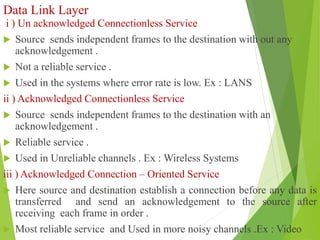
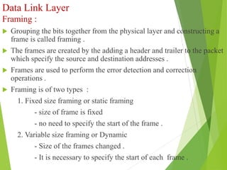
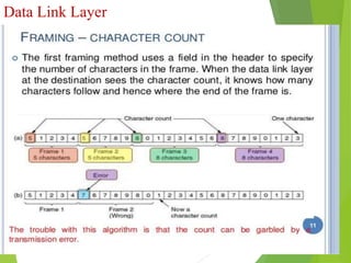
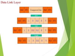
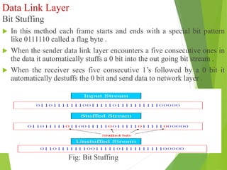
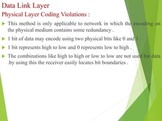
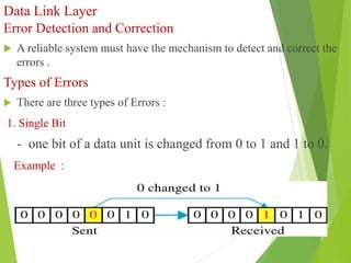
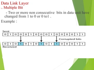
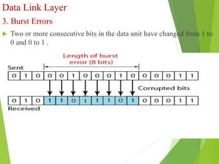
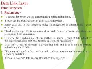
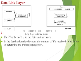
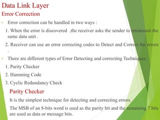
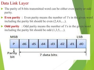
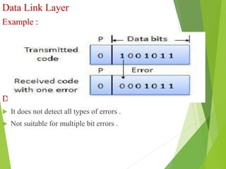
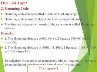
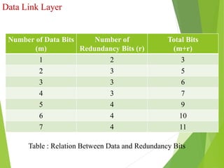
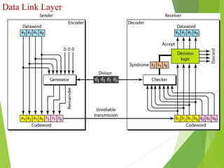
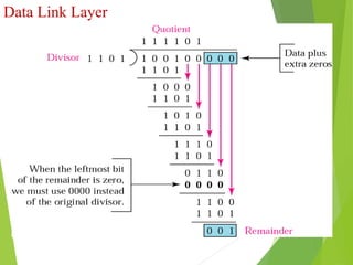
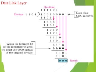
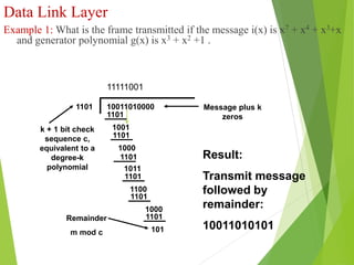
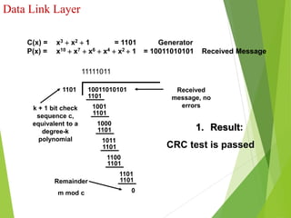
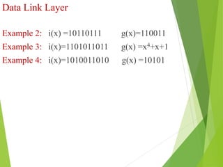
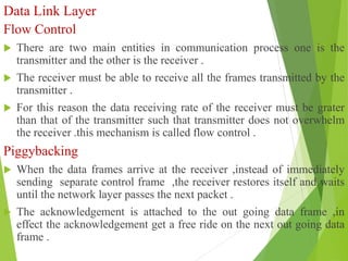
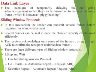
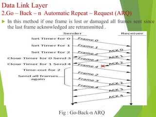
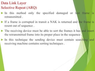
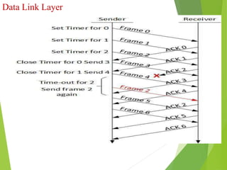
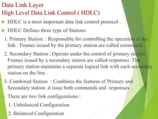
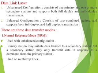
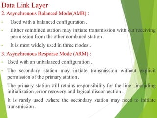
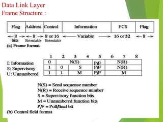
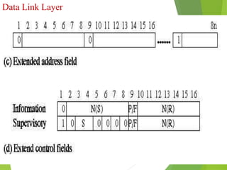
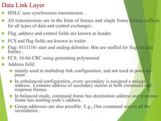
1. UNIT-2
• Design Issues in Data link Layer
• Framing
• Error Detection and Correction
- Parity Check
- CRC
- Hamming Code
• Flow Control
- Sliding Window Protocols
• HDLC
• PPP
2. Unit - II
DATA-LINK LAYER & MEDIAACCESS
Introduction – Link-Layer Addressing –
DLC Services – Data-Link Layer Protocols
– HDLC – PPP – Media Access Control –
Wired LANs: Ethernet – Wireless LANs –
Introduction – IEEE 802.11, Bluetooth –
Connecting Devices.
Behrouz A. Forouzan, Data Communications and Networking, Fifth Edition
TMH, 2013
3. Data Link Layer
Design Issues :
Design Issues of Data link layer are :
1. Service Provided to the Network Layer
2. Framing
3. Error Detection and Correction
4. Flow Control
1. Service Provided to the Network Layer
Data link layer provides three services to the network layer .
i ) Un acknowledged Connectionless Service
ii ) Acknowledged Connection less Service
iii ) Acknowledged Connection Oriented Service
4. Data Link Layer
i ) Un acknowledged Connectionless Service
Source sends independent frames to the destination with out any
acknowledgement .
Not a reliable service .
Used in the systems where error rate is low. Ex : LANS
ii ) Acknowledged Connectionless Service
Source sends independent frames to the destination with an
acknowledgement .
Reliable service .
Used in Unreliable channels . Ex : Wireless Systems
iii ) Acknowledged Connection – Oriented Service
Here source and destination establish a connection before any data is
transferred and send an acknowledgement to the source after
receiving each frame in order .
Most reliable service and Used in more noisy channels .Ex : Video
5. Data Link Layer
Framing :
Grouping the bits together from the physical layer and constructing a
frame is called framing .
The frames are created by the adding a header and trailer to the packet
which specify the source and destination addresses .
Frames are used to perform the error detection and correction
operations .
Framing is of two types :
1. Fixed size framing or static framing
- size of frame is fixed
- no need to specify the start of the frame .
2. Variable size framing or Dynamic
- Size of the frames changed .
- It is necessary to specify the start of each frame .
6. Data Link Layer
Methods to Break the Bit Stream into Frames .
1. Character Count
2. Character Stuffing or Byte Stuffing
3. Bit Stuffing
4. Physical Layer Coding Violations .
Character Count
Here a field in the header ,Specifies the number of characters in the
frame .
Data link layer at the destination looks the character count and deside
the end of frame .
The main draw back of this method is if any count is garbled by a
transmission error then the destination is unable to decide the frames .
8. Data Link Layer
Character Stuffing or Byte Stuffing
In this method each frame starts with the ASCII character sequence
DLE STX and ends with DLE ETX .
DLE STX and DLE ETX sequences are called frame boundaries .
It is possible to occur DLESTX or DLEETX in the data ,which will
interfere the frame .
To solve this problem the data link layer at ender side stuff an ASCII
DLE character just before each accidental DLE character in the data .
The Data link layer at receiving end removes this DLE before giving
the data to network layer .
Disadvantage of this method is more overhead and each frame is tied
with 8 bit characters .
10. Data Link Layer
Bit Stuffing
In this method each frame starts and ends with a special bit pattern
like 0111110 called a flag byte .
When the sender data link layer encounters a five consecutive ones in
the data it automatically stuffs a 0 bit into the out going bit stream .
When the receiver sees five consecutive 1’s followed by a 0 bit it
automatically destuffs the 0 bit and send data to network layer .
Fig: Bit Stuffing
11. Data Link Layer
Physical Layer Coding Violations :
This method is only applicable to network in which the encoding on
the physical medium contains some redundancy .
1 bit of data may encode using two physical bits like 0 and 1 .
1 bit represents high to low and 0 represents low to high .
The combinations like high to high or low to low are not used for data
.by using this the receiver easily locates bit boundaries .
12. Data Link Layer
Error Detection and Correction
A reliable system must have the mechanism to detect and correct the
errors .
Types of Errors
There are three types of Errors :
1. Single Bit
- one bit of a data unit is changed from 0 to 1 and 1 to 0.
Example :
13. Data Link Layer
2. Multiple Bit
- Two or more non consecutive bits in data unit have
changed from 1 to 0 or 0 to1 .
Example :
Fig : Multiple Bit Errors
14. Data Link Layer
3. Burst Errors
Two or more consecutive bits in the data unit have changed from 1 to
0 and 0 to 1 .
Fig : Burst Errors
15. Data Link Layer
Error Detection
1. Redundency
To detect the errors we use a mechanism called redundancy .
It involves the transmission of each data unit twice .
Same data unit is not received twice in succession a transmission error
occurred .
The disadvantage of this system is slow and if an error occurred at the same
position of both data units .
To avoid the disadvantage of this method a shorter group of bits added to
the end of each data unit ,this technique is called redundancy
Data unit is passed through a generating unit and it adds an appropriate
redundancy check bits .
This data unit send to the receiver and receiver puts the entire stream into a
checking function .
If there is no error data is accepted other wise rejected .
16. Data Link Layer
Fig : Redundency
2. Exact –Count Encoding :
The Number of 1’s in the data unit are same .
In the destination side it count the number of 1’s received same or not
to determine the transmission error .
17. Data Link Layer
Error Correction
• Error correction can be handled in two ways :
1. When the error is discovered ,the receiver asks the sender to retransmit the
same data unit .
2. Receiver can use an error correcting codes to Detect and Correct the errors
.
• There are different types of Error Detecting and correcting Techniques :
1. Parity Checker
2. Hamming Code
3. Cyclic Redundancy Check
1. Parity Checker
• It is the simplest technique for detecting and correcting errors.
• The MSB of an 8-bits word is used as the parity bit and the remaining 7 bits
are used as data or message bits.
18. Data Link Layer
The parity of 8-bits transmitted word can be either even parity or odd
parity.
Even parity : Even parity means the number of 1's in the given word
including the parity bit should be even (2,4,6,....).
Odd parity : Odd parity means the number of 1's in the given word
including the parity bit should be odd (1,3,5,....).
19. Data Link Layer
Example :
Drawbacks
It does not detect all types of errors .
Not suitable for multiple bit errors .
20. Data Link Layer
2. Hamming Code
Hamming code can be applied to data units of any length .
Hamming code is used to detect and correct single bit errors .
The distance between two words of the same size is called Hamming
distance.
Example :
1. The Hamming distance d(000, 011) is 2 because 000 +011 is 011
(two 1’s).
2. The Hamming distance d(10101, 11110) is 3 because 10101 +11110
is 01011 (three 1’s).
To calculate the number of redundancy bits (r) required to correct a
given number of data bits (m ) it should satisfy a condition :
2r>=m+r+1
21. Data Link Layer
Number of Data Bits
(m)
Number of
Redundancy Bits (r)
Total Bits
(m+r)
1 2 3
2 3 5
3 3 6
4 3 7
5 4 9
6 4 10
7 4 11
Table : Relation Between Data and Redundancy Bits
22. Data Link Layer
The redundancy bits in the original data are placed in powers of 2 like
1 ,2,4,8,16 etc .
Fig : Position of Redundancy bits in hamming code
r1 is selected so as to establish even parity in bit positions :
1,3,5,7,9,11 .
r2 is selected so as to establish even parity in bit positions :
2,3,6,7,10,11 .
r1 is selected so as to establish even parity in bit positions : 4,5,6,7.
r1 is selected so as to establish even parity in bit positions : 8,9,10,11
23. Data Link Layer
If any combination the number of 1’s even number ,assign the
corresponding r value as 0 else 1 .
Like this after knowing the values of r1,r2,r4 and r8 the error bit
location can be identified by r’s position ( r8 r4 r2 r1).
All values of r’s zero indicates no error has occurred .
Example 1: Consider the message 1001101 is transmitted through the
channel ,obtain the redundancy bits and transmitting unit needed.
Assume bit number 8 has been changed .how to locate it.
Example 2: Consider the message 1010111 is transmitted through the
channel ,obtain the redundancy bits and transmitting unit needed.
Assume bit number 3 has been changed .how to locate it.
Example 3: Consider the message 1101100 is transmitted through the
channel ,obtain the redundancy bits and transmitting unit needed.
Assume bit number 5 has been changed .how to locate it.
24. Data Link Layer
CRC (Cyclic Redundancy Check)
Most power full redundancy technique based on the binary division .
It uses polynomial codes for generating check bits in the form of
cyclic redundancy check .
crc bits are appended at the end of each data unit so that the resulting
data unit becomes exactly divisible by a second ,predetermined
number .
At the receiver the incoming data unit is divided by the same number .
If there is no reminder the data unit is intact and it is accepted .
A reminder indicates that data unit has damaged .
29. Data Link Layer
Example 1: What is the frame transmitted if the message i(x) is x7 + x4 + x3+x
and generator polynomial g(x) is x3 + x2 +1 .
1001
1101
1000
1101
1011
1101
1100
1101
1000
1101
1101
k + 1 bit check
sequence c,
equivalent to a
degree-k
polynomial
101
1101
Remainder
m mod c
10011010000 Message plus k
zeros
Result:
Transmit message
followed by
remainder:
10011010101
11111001
30. Data Link Layer
1001
1101
1000
1101
1011
1101
1100
1101
1101
1101
1101
k + 1 bit check
sequence c,
equivalent to a
degree-k
polynomial
0
1101
Remainder
m mod c
10011010101 Received
message, no
errors
1. Result:
CRC test is passed
C(x) = x3 x2 1 = 1101 Generator
P(x) = x10 x7 x6 x4 x2 1 = 10011010101 Received Message
11111011
31. Data Link Layer
Example 2: i(x) =10110111 g(x)=110011
Example 3: i(x)=1101011011 g(x) =x4+x+1
Example 4: i(x)=1010011010 g(x) =10101
32. Data Link Layer
Flow Control
There are two main entities in communication process one is the
transmitter and the other is the receiver .
The receiver must be able to receive all the frames transmitted by the
transmitter .
For this reason the data receiving rate of the receiver must be grater
than that of the transmitter such that transmitter does not overwhelm
the receiver .this mechanism is called flow control .
Piggybacking
When the data frames arrive at the receiver ,instead of immediately
sending separate control frame ,the receiver restores itself and waits
until the network layer passes the next packet .
The acknowledgement is attached to the out going data frame ,in
effect the acknowledgement get a free ride on the next out going data
frame .
33. Data Link Layer
The technique of temporarily delaying the out going
acknowledgement so that they can be hooked on to the next out going
frame , which is known as “piggy backing “ .
Sliding Window Protocols
In this mechanism the sender can transmit several frames before
requiring an acknowledgement .
Several frames can be sent at once the channel capacity can be used
efficiently .
The receiver acknowledges only some of the frames , using a single
ACK to confirm the receipt of multiple data frames .
There are three different types of Sliding window protocols .
1.Stop and Wait
1. One bit Sliding Window Protocol
2. Go – Back – n Automatic Repeat – Request (ARQ)
3. Selective Repeat – Automatic Repeat Request (ARQ)
34. Data Link Layer
1. One bit Sliding Window Protocol
Fig : (a) At start. Receiver waits for 0.
(b) Sender sends 0.
(c) Receiver receives 0. Waits for 1.
(d) Sender got ack for 0. Hasn't got 1 from its Network layer yet.
35. Data Link Layer
Fig : a. Normal( seq , Ack , Packet number)
b. Synchronization Problem
36. Data Link Layer
2.Go – Back – n Automatic Repeat – Request (ARQ)
In this method if one frame is lost or damaged all frames sent since
the last frame acknowledged are retransmitted .
Fig : Go-Back-n ARQ
37. Data Link Layer
Selective Repeat (ARQ)
In this method only the specified damaged or lost frame is
retransmitted .
If a frame is corrupted in transit a NAK is returned and the frame is
resent out of sequence .
The receiving device must be able to sort the frames it has and insert
the retransmitted frame into its proper place in the sequence .
In this technique the sending device must contain searching and
receiving machine contains sorting techniques .
39. Data Link Layer
High Level Data Link Control ( HDLC)
HDLC is a most important data link control protocol .
HDLC Defines three type of Stations
1. Primary Station : Responsible for controlling the operation of the
link . Frames issued by the primary station are called commands .
2. Secondary Station : Operate under the control of primary station .
Frames issued by a secondary station are called responses .The
primary station maintains a separate logical link with each secondary
station on the line .
3. Combined Station : Combines the features of Primary and
Secondary station .it issue both commands and responses .
There are two link configurations :
1. Unbalanced Configuration
2. Balanced Configuration
40. Data Link Layer
1. Unbalanced Configuration : consists of one primary and one or more
secondary stations and supports both full duplex and half- duplex
transmission.
2. Balanced Configuration : Consists of two combined stations and
supports both full-duplex and half duplex transmission .
There are three data transfer modes :
1.Normal Response Mode (NRM):
Used with unbalanced configuration .
Primary station may initiate data transfer to a secondary station ,but
a secondary station may only transmit data in response to a
command from the primary station .
Used on multidrop lines .
41. Data Link Layer
2. Asynchronous Balanced Mode(AMB) :
• Used with a balanced configuration .
• Either combined station may initiate transmission with out receiving
permission from the other combined station .
• It is most widely used in three modes .
3. Asynchronous Response Mode (ARM) :
• Used with an unbalanced configuration .
• The secondary station may initiate transmission without explicit
permission of the primary station .
• The primary station still retains responsibility for the line ,including
initialization ,error recovery and logical disconnection .
• It is rarely used .where the secondary station may need to initiate
transmission .
44. Data Link Layer
HDLC uses synchronous transmission .
All transmissions are in the form of frames and single frame format suffices
for all types of data and control exchanges .
Flag ,address and control fields are known as header.
FCS and flag fields are known as trailer .
Flag: 0111110- start and ending delimiter. Bits are stuffed for flags in data
frames .
FCS: 16-bit CRC using generating polynomial
Address field:
mainly used in multidrop link configuration, and not used in point-to-
point
In unbalanced configuration, every secondary is assigned a unique
address. Contains address of secondary station in both command and
response frames
In balanced mode, command frame has destination address and response
frame has sending node’s address .
Group addresses are also possible. E.g., One command sent to all the
secondaries .
45. Data Link Layer
In I-frames, N(s) is the sequence number of the frame being sent, and
R(s) is the sequence number of the frame being expected.
The P/F bit, known as the poll/final bit, is used with different meaning
in different contexts.
It is used to indicate polling, to indicate the final I-frame, etc
There are three different classes of frames used in HDLC
Unnumbered frames, used in link setup and disconnection, and
hence do not contain ACK.
Information frames, which carry actual information. Such frames
can piggyback ACK in case of ABM
Supervisory frames, which are used for error and flow control
purposes and hence contain send and receive sequence numbers
46. Data Link Layer
Point to Point Protocol (PPP)
• One sender, one receiver, one link: easier than broadcast link:
• No Media Access Control
• No need for explicit MAC addressing
• E.g., dialup link, ISDN line
• Popular point-to-point and high-level DLC protocols:
• PPP (point-to-point protocol)
• HDLC: High level data link control (Data link used to be considered “high layer” in protocol stack). HDLC
is also used in multi-point links (one station many receivers)
• These protocols can often be run over other data link technologies
providing best of both worlds
– E.g., PPPoE, HDLC encapsulation by Ethernet
47. Data Link Layer
Functionality : (similar to link layer services + extra management
functions)
• Packet framing - encapsulation of network-layer datagram in data
link frame
– Multi-protocol - carry network layer data of any network layer
protocol (not just IP) at same time ability to demultiplex upwards
• Bit transparency - must carry any bit pattern in the data field (even if
underlying channel can't)
• Error detection - not correction
PPP Data Frame Format
48. Data Link Layer
• Flag: delimiter (framing)
• Address: ignored. (historical)
• Control: ignored. (historical)
• Protocol: upper layer protocol to which frame delivered (e.g., PPP-
LCP, IP, IPCP, etc)
• info: upper layer data being carried
• check: cyclic redundancy check for error detection
Where does PPP get used?
• Dial-up – PPP over async serial, over modem
• ADSL – PPP over Ethernet
• Backbone – Packet over SONET (POS)
• Why?
– Framing (dialup, POS)
– Efficiency (POS)
– Authentication, address negotiation (PPPoE)