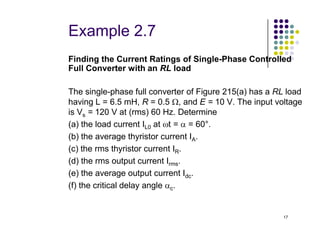
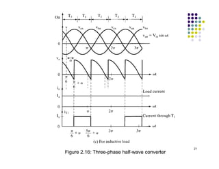
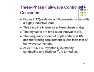
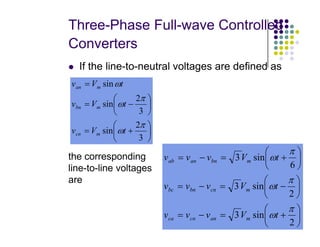
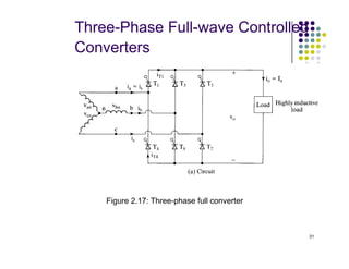
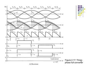
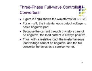
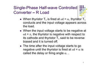
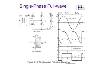
This document describes single-phase and three-phase half-wave and full-wave controlled rectifier circuits. It discusses the operation of these circuits, including which thyristors are conducting during different periods of the input voltage cycle. Key waveforms like input voltage, output voltage, and load current are shown. Equations are provided for calculating average and RMS output voltage and current values for different circuit configurations. Examples are given to demonstrate how to determine performance metrics like efficiency and voltage/current ratings for a single-phase full-wave converter with an RL load.


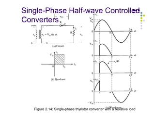
![Single-Phase Half-wave Controlled
Converter – R Load (π
π
π
π in radian )
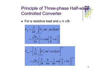
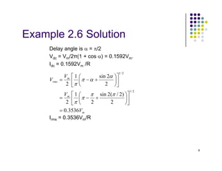
If Vm is the peak input voltage, the average
output voltage Vdc can be found from.
The maximum output voltage Vdm is (a=0)
( ) [ ] ( )
α
π
ω
π
ω
ω
π
π
α
π
α
cos
1
2
cos
2
sin
2
1
+
=
−
=
= ∫
m
m
m
dc
V
t
V
t
td
V
V
5
The maximum output voltage Vdm is (a=0)
The normalized output voltage
π
m
dm
V
V =
( )
α
cos
1
5
.
0 +
=
=
dm
dc
n
V
V
V](https://image.slidesharecdn.com/chapter3-230622143856-b5216db2/85/Chapter-3-Controlled-Rectifier-pdf-5-320.jpg)

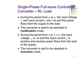
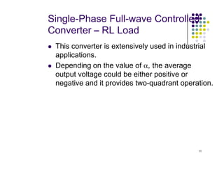
![Single-Phase Full-wave Controlled
Converter – RL Load
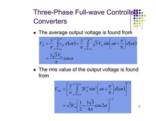
The average output voltage
The rms value of the output voltage
( ) [ ] α
π
ω
π
ω
ω
π
α
π
α
α
π
α
cos
2
cos
2
2
sin
2
2 m
m
m
dc
V
t
V
t
td
V
V =
−
=
=
+
+
∫
13
The rms value of the output voltage
( )
( ) ( ) s
m
m
m
rms
V
V
t
d
t
V
t
td
V
V
=
=
−
=
=
∫
∫
+
+
2
2
cos
1
2
sin
2
2
2
/
1
2
2
/
1
2
2
α
π
α
α
π
α
ω
ω
π
ω
ω
π](https://image.slidesharecdn.com/chapter3-230622143856-b5216db2/85/Chapter-3-Controlled-Rectifier-pdf-13-320.jpg)
![Single-Phase Full-wave Controlled
Converter – RL Load
The load current iL.
mode 1 : when T1 and T2 conduct [α ≤ ωt ≤ (α + π)]
( ) ( ) ( )( )
t
L
R
s
L
s
L e
Z
V
R
E
I
R
E
t
Z
V
i −
−
−
+
+
−
−
= ω
α
θ
α
θ
ω /
/
0 sin
2
sin
2
for
14
The steady-state condition iL (ωt = π + α) = IL1 =
IL0.
( ) ( ) ( )( )
( )( )
R
E
e
e
Z
V
I
I L
R
L
R
s
L
L −
−
−
−
−
−
=
= −
−
ω
π
ω
π
θ
α
θ
α
/
/
/
/
1
0
1
sin
sin
2
0
0 ≥
L
I](https://image.slidesharecdn.com/chapter3-230622143856-b5216db2/85/Chapter-3-Controlled-Rectifier-pdf-14-320.jpg)
![Single-Phase Full-wave Controlled
Converter – RL Load
The rms current.
mode 1 : when T1 and T2 conduct [α ≤ ωt ≤ (α + π)]
( )
2
/
1
2
2
1
= ∫
+α
π
α
ω
π
t
d
i
I L
R
15
The rms output current.
The average current
( ) R
R
R
rms I
I
I
I 2
2
/
1
2
2
=
+
=
( )
∫
+
=
α
π
α
ω
π
t
d
i
I L
A
2
1](https://image.slidesharecdn.com/chapter3-230622143856-b5216db2/85/Chapter-3-Controlled-Rectifier-pdf-15-320.jpg)
![Single-Phase Full-wave Controlled
Converter – RL Load
The average output current.
mode 1 : when T1 and T2 conduct [α ≤ ωt ≤ (α + π)]
A
A
A
dc I
I
I
I 2
=
+
=
16](https://image.slidesharecdn.com/chapter3-230622143856-b5216db2/85/Chapter-3-Controlled-Rectifier-pdf-16-320.jpg)