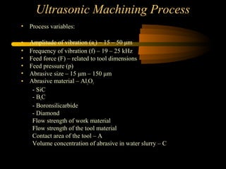
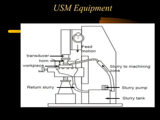
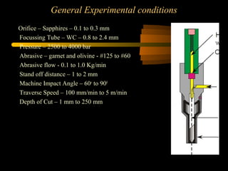
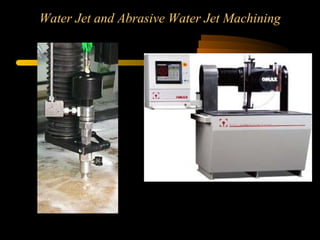
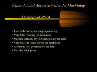
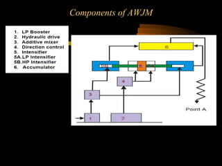
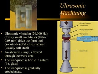
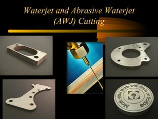
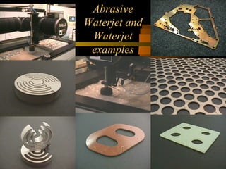
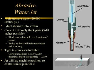
Unconventional Machining
Processes- Part-1
Presented By
Prof.S.Sathishkumar
Assistant Professor
Department of Mechanical Engineering
Vel Tech (Engineering College)
Avadi-Chennai-62
Outline
Non-traditional Machining Processes
– Abrasive Jet Machining
– Water Jet Machining
– Abrasive Water Jet Machining
– Ultrasonic Machining
– Chemical Machining
– Electro-chemical Machining
– Electro discharge Machining
– Laser Beam Machining
– Plasma Arc Machining
– Electron Beam Machining
– Overall Process comparisons
Non-traditional Machining Processes
Manufacturing processes can be broadly divided into two groups:
a) primary manufacturing processes : Provide basic shape and size
b) secondary manufacturing processes : Provide final shape and size with
tighter control on dimension, surface characteristics
Material removal processes once again can be divided into two groups
1. Conventional Machining Processes
2. Non-Traditional Manufacturing Processes or non-conventional
Manufacturing processes
Conventional Machining Processes mostly remove material in the form
of chips by applying forces on the work material with a wedge shaped
cutting tool that is harder than the work material under machining
condition.
Non-traditional Machining Processes
The major characteristics of conventional machining are:
– • Generally macroscopic chip formation by shear deformation
– • Material removal takes place due to application of cutting forces
– energy domain can be classified as mechanical
– • Cutting tool is harder than work piece at room temperature as
well as under machining conditions
Non-conventional manufacturing processes is defined as a group of
processes that remove excess material by various techniques
involving mechanical, thermal, electrical or chemical energy or
combinations of these energies but do not use a sharp cutting tools as
it needs to be used for traditional manufacturing processes.
The major characteristics of Non-conventional machining are:
1. Material removal may occur with chip formation or even no chip
formation may take place. For example in AJM, chips are of
microscopic size and in case of Electrochemical machining material
removal occurs due to electrochemical dissolution at atomic level.
Non-traditional Machining Processes
The major characteristics of Non-conventional machining:
2. In NTM, there may not be a physical tool present. For example in laser
jet machining, machining is carried out by laser beam. However in
Electrochemical Machining there is a physical tool that is very much
required for machining
3. In NTM, the tool need not be harder than the work piece material. For
example, in EDM, copper is used as the tool material to machine
hardened steels.
4. Mostly NTM processes do not necessarily use mechanical energy to
provide material removal. They use different energy domains to provide
machining. For example, in USM, AJM, WJM mechanical energy is
used to machine material, whereas in ECM electrochemical dissolution
constitutes material removal.
Classification of NTM processes
classification of NTM processes is carried out depending on the nature of
energy used for material removal.
1. Mechanical Processes
• Abrasive Jet Machining (AJM)
• Ultrasonic Machining (USM)
• Water Jet Machining (WJM)
• Abrasive Water Jet Machining (AWJM)
2. Electrochemical Processes
• Electrochemical Machining (ECM)
• Electro Chemical Grinding (ECG)
• Electro Jet Drilling (EJD)
3. Electro-Thermal Processes
• Electro-discharge machining (EDM)
• Laser Jet Machining (LJM)
• Electron Beam Machining (EBM)
4. Chemical Processes
• Chemical Milling (CHM)
• Photochemical Milling (PCM)
Needs for Non Traditional Machining
• Extremely hard and brittle materials or Difficult to machine materials are
difficult to machine by traditional machining processes.
• When the workpiece is too flexible or slender to support the cutting or
grinding forces.
• When the shape of the part is too complex.
• Intricate shaped blind hole – e.g. square hole of 15 mmx15 mm with a depth
of 30 mm
• Deep hole with small hole diameter – e.g. φ 1.5 mm hole with l/d = 20
• Machining of composites.
Abrasive Jet Machining
In Abrasive Jet Machining (AJM), abrasive particles are made to impinge on the
work material at a high velocity. The high velocity abrasive particles remove the
material by micro-cutting action as well as brittle fracture of the work material.
Abrasive Jet Machining
In AJM, generally, the abrasive particles of around 50 μm grit size would
impinge on the work material at velocity of 200 m/s from a nozzle of I.D.
of 0.5 mm with a stand off distance of around 2 mm. The kinetic energy of
the abrasive particles would be sufficient to provide material removal due
to brittle fracture of the work piece or even micro cutting by the abrasives.
Abrasive Jet Machining
AJM set-up
Abrasive Jet Machining
Process Parameters and Machining Characteristics
Abrasive : Material – Al2O3 / SiC
–Shape – irregular / spherical
–Size – 10 ~ 50 μm
–Mass flow rate – 2 ~ 20 gm/min
Carrier gas : Composition – Air, CO2, N2
• Density – Air ~ 1.3 kg/m3
• Velocity – 500 ~ 700 m/s
• Pressure – 2 ~ 10 bar
• Flow rate – 5 ~ 30 lpm
Abrasive Jet : Velocity – 100 ~ 300 m/s
Mixing ratio – mass flow ratio of abrasive to gas
Stand-off distance – 0.5 ~ 5 mm
Impingement Angle – 600
~ 900
Nozzle : Material – WC
Diameter – (Internal) 0.2 ~ 0.8 mm
Life – 10 ~ 300 hours
Abrasive Jet Machining
effect of process parameters on MRR
Abrasive Jet Machining
Modelling of material removal
Material removal in AJM takes place due to brittle fracture of the work
material due to impact of high velocity abrasive particles.
Modelling has been done with the following assumptions:
– (i) Abrasives are spherical in shape and rigid. The particles are
characterised by the mean grit diameter
– (ii) The kinetic energy of the abrasives are fully utilised in
removing material
– (iii) Brittle materials are considered to fail due to brittle fracture
and the fracture volume is considered to be hemispherical with
diameter equal to chordal length of the indentation
– (iv) For ductile material, removal volume is assumed to be equal to
the indentation volume due to particulate impact.
Ultrasonic Machining Process
• USM for machining brittle work material
• Material removal primarily occurs due to the indentation of the hard
abrasive grits on the brittle work material.
• Other than this brittle failure of the work material due to indentation
some material removal may occur due to free flowing impact of the
abrasives against the work material and related solid-solid impact
erosion,
• Tool’s vibration – indentation by the abrasive grits.
• During indentation, due to Hertzian contact stresses, cracks would
develop just below the contact site, then as indentation progresses the
cracks would propagate due to increase in stress and ultimately lead
to brittle fracture of the work material under each individual
interaction site between the abrasive grits and the workpiece.
• The tool material should be such that indentation by the abrasive grits
does not lead to brittle failure.
• Thus the tools are made of tough, strong and ductile materials like
steel, stainless steel and other ductile metallic alloys.
Ultrasonic Machining Process
• Process variables:
• Amplitude of vibration (ao) – 15 – 50 μm
• Frequency of vibration (f) – 19 – 25 kHz
• Feed force (F) – related to tool dimensions
• Feed pressure (p)
• Abrasive size – 15 μm – 150 μm
• Abrasive material – Al2O3
- SiC
- B4C
- Boronsilicarbide
- Diamond
Flow strength of work material
Flow strength of the tool material
Contact area of the tool – A
Volume concentration of abrasive in water slurry – C
USM Equipment
Modelling
Modelling
Modelling
Modelling
Water Jet and Abrasive Water Jet Machining
• WJM - Pure
• WJM - with stabilizer
• AWJM – entrained – three phase –
abrasive, water and air
• AWJM – suspended – two phase –
abrasive and water
o Direct pumping
o Indirect pumping
o Bypass pumping
General Experimental conditions
Orifice – Sapphires – 0.1 to 0.3 mm
Focussing Tube – WC – 0.8 to 2.4 mm
Pressure – 2500 to 4000 bar
Abrasive – garnet and olivine - #125 to #60
Abrasive flow - 0.1 to 1.0 Kg/min
Stand off distance – 1 to 2 mm
Machine Impact Angle – 60o
to 900
Traverse Speed – 100 mm/min to 5 m/min
Depth of Cut – 1 mm to 250 mm
Water Jet and Abrasive Water Jet Machining
• Extremely fast set-up and programming
• Very little fixturing for most parts
• Machine virtually any 2D shape on any material
• Very low side forces during the machining
• Almost no heat generated on the part
• Machine thick plates
Advantages of AWJM
Components of AWJM
Components of AWJM
Components of AWJM
Components of AWJM
Catcher
(c) catcher plates
(TiB2)
(b) steel/WC/ceramic balls
(a) water basin
Modelling
Photographic view of kerf (cross section)
Grinding
Abrasive Grinding
• Can be viewed as
multiple very small
cutting edges
• Results in a very fine
finish
• Can leave residual
stresses
• Slow, small material
removal rates
• Sparking out
Standard Grinding Wheel
Designation
• While this is specific to grinding, realize that there are
similar standard designations in most industries
• Take the time to learn the standard designations early so
that you can speak intelligibly with those within the
industry.
Ultrasonic
Machining
• Ultrasonic vibration (20,000 Hz)
of very small amplitudes (0.04-
0.08 mm) drive the form tool
(sonotrode) of ductile material
(usually soft steel)
• An abrasive slurry is flowed
through the work area
• The workpiece is brittle in nature
(i.e. glass)
• The workpiece is gradually
eroded away.
Waterjet and Abrasive Waterjet
(AWJ) Cutting
Abrasive
Waterjet and
Waterjet
examples
Abrasive
Water Jet
• High pressure water (20,000-
60,000 psi)
• Educt abrasive into stream
• Can cut extremely thick parts (5-10
inches possible)
– Thickness achievable is a function of
speed
– Twice as thick will take more than
twice as long
• Tight tolerances achievable
– Current machines 0.002” (older
machines much less capable ~ 0.010”
• Jet will lag machine position, so
controls must plan for it
Chemical Machining (Chemilling)
• Applications:
– Aerospace industry
– Engraving
– Circuit boards
• A maskant is applied over
areas you don’t want to
machine
– Photochemical methods
– Apply maskant to entire surface
and use laser to cut
• Place the entire part in a
chemical bath (acid or alkali
depending upon the metal)
• Control temperature and time
of exposure to control
material removal
Electro-Chemical
Machining (ECM)
• Works on the principle of
electrolysis – accelerated
chemilling
• Die is progressively
lowered into workpiece as
workpiece is dissociated
into ions by electrolysis
• Electrolytic fluid flows
around workpiece to
remove ions and maintain
electrical current path
• Low DC voltage, very
High current (700 amps)
Electrochemical grinding
• Combines electrochemical machining with
conventional grinding
– Grinding wheel is the cathode
– Metal bonded wheel with diamond or Al2O3
abrasive
– Majority of material removal from electrolytic
action (95%) therefore very low wheel wear
– Much faster than conventional grinding
Electrode Discharge
Machining (EDM)
• Direct Competitor of ECM – much more
common than ECM
• The tool acts as a cathode (typically
graphite) is immersed in a Dielectric fluid
with conductive workpiece
• DC voltage (~300V) is applied. As
voltage builds up over gap between
workpiece and tool, eventually you get
dielectric breakdown (sparking at around
12,000 deg F)
• The sparking erodes the workpiece in the
shape of the tool
• The tool is progressively lowered by CNC
as the workpiece erodes
• Cycle is repeated at 200,000-500,000 Hz
• Dielectric:
– Cools tool and workpiece
– Flushes out debris from work area
Die Sinker
vs. Wire
EDM
• Die sinker EDM
– The die sinks into the part
as it sparks away the
workpiece
– Most common Injection
molding die process
• Wire EDM
– The electrode is a wire that
traverses through the part
– Common for Extrusion
Dies
Laser Beam Machining
• Lasers are high intensity focused light sources
– CO2
• Most widely used
• Generally more powerful that YAG lasers
• Cutting operations commonly
– Nd:YAG (Neodymium ions in an Yttrium Aluminum
Garnet)
• Less powerful
• Etching/marking type operations more commonly
• Limited in depth of cut (focus of light)
• Would limit workpiece to less than 1 inch (< ½”
typically)
Case Study
• CNC Mill
• CNC Wire EDM
• CNC EDM
Wire EDM (not shown), Die Sinker
EDM, Anodized
Different Part - Wire EDM –
profiling and drilling
Case Study Three
1. CNC Milling 2. Setup on wire EDM
3. QA After wire EDM 4. Grinding a face on the part
Setup of Die Sinker EDM
1. Locating parts relative to
machine
2. Locating the electrode
relative to parts setup
Die Sinker in action and finished
product
Overall Machining Tolerances and Surface
Roughness
Wish you Happy Learning My Dear Hearts

UNCONVENTIONAL MACHINING PROCESS

  • 1.
    Unconventional Machining Processes- Part-1 PresentedBy Prof.S.Sathishkumar Assistant Professor Department of Mechanical Engineering Vel Tech (Engineering College) Avadi-Chennai-62
  • 2.
    Outline Non-traditional Machining Processes –Abrasive Jet Machining – Water Jet Machining – Abrasive Water Jet Machining – Ultrasonic Machining – Chemical Machining – Electro-chemical Machining – Electro discharge Machining – Laser Beam Machining – Plasma Arc Machining – Electron Beam Machining – Overall Process comparisons
  • 3.
    Non-traditional Machining Processes Manufacturingprocesses can be broadly divided into two groups: a) primary manufacturing processes : Provide basic shape and size b) secondary manufacturing processes : Provide final shape and size with tighter control on dimension, surface characteristics Material removal processes once again can be divided into two groups 1. Conventional Machining Processes 2. Non-Traditional Manufacturing Processes or non-conventional Manufacturing processes Conventional Machining Processes mostly remove material in the form of chips by applying forces on the work material with a wedge shaped cutting tool that is harder than the work material under machining condition.
  • 4.
    Non-traditional Machining Processes Themajor characteristics of conventional machining are: – • Generally macroscopic chip formation by shear deformation – • Material removal takes place due to application of cutting forces – energy domain can be classified as mechanical – • Cutting tool is harder than work piece at room temperature as well as under machining conditions Non-conventional manufacturing processes is defined as a group of processes that remove excess material by various techniques involving mechanical, thermal, electrical or chemical energy or combinations of these energies but do not use a sharp cutting tools as it needs to be used for traditional manufacturing processes. The major characteristics of Non-conventional machining are: 1. Material removal may occur with chip formation or even no chip formation may take place. For example in AJM, chips are of microscopic size and in case of Electrochemical machining material removal occurs due to electrochemical dissolution at atomic level.
  • 5.
    Non-traditional Machining Processes Themajor characteristics of Non-conventional machining: 2. In NTM, there may not be a physical tool present. For example in laser jet machining, machining is carried out by laser beam. However in Electrochemical Machining there is a physical tool that is very much required for machining 3. In NTM, the tool need not be harder than the work piece material. For example, in EDM, copper is used as the tool material to machine hardened steels. 4. Mostly NTM processes do not necessarily use mechanical energy to provide material removal. They use different energy domains to provide machining. For example, in USM, AJM, WJM mechanical energy is used to machine material, whereas in ECM electrochemical dissolution constitutes material removal.
  • 6.
    Classification of NTMprocesses classification of NTM processes is carried out depending on the nature of energy used for material removal. 1. Mechanical Processes • Abrasive Jet Machining (AJM) • Ultrasonic Machining (USM) • Water Jet Machining (WJM) • Abrasive Water Jet Machining (AWJM) 2. Electrochemical Processes • Electrochemical Machining (ECM) • Electro Chemical Grinding (ECG) • Electro Jet Drilling (EJD) 3. Electro-Thermal Processes • Electro-discharge machining (EDM) • Laser Jet Machining (LJM) • Electron Beam Machining (EBM) 4. Chemical Processes • Chemical Milling (CHM) • Photochemical Milling (PCM)
  • 7.
    Needs for NonTraditional Machining • Extremely hard and brittle materials or Difficult to machine materials are difficult to machine by traditional machining processes. • When the workpiece is too flexible or slender to support the cutting or grinding forces. • When the shape of the part is too complex. • Intricate shaped blind hole – e.g. square hole of 15 mmx15 mm with a depth of 30 mm • Deep hole with small hole diameter – e.g. φ 1.5 mm hole with l/d = 20 • Machining of composites.
  • 8.
    Abrasive Jet Machining InAbrasive Jet Machining (AJM), abrasive particles are made to impinge on the work material at a high velocity. The high velocity abrasive particles remove the material by micro-cutting action as well as brittle fracture of the work material.
  • 9.
    Abrasive Jet Machining InAJM, generally, the abrasive particles of around 50 μm grit size would impinge on the work material at velocity of 200 m/s from a nozzle of I.D. of 0.5 mm with a stand off distance of around 2 mm. The kinetic energy of the abrasive particles would be sufficient to provide material removal due to brittle fracture of the work piece or even micro cutting by the abrasives.
  • 10.
  • 11.
    Abrasive Jet Machining ProcessParameters and Machining Characteristics Abrasive : Material – Al2O3 / SiC –Shape – irregular / spherical –Size – 10 ~ 50 μm –Mass flow rate – 2 ~ 20 gm/min Carrier gas : Composition – Air, CO2, N2 • Density – Air ~ 1.3 kg/m3 • Velocity – 500 ~ 700 m/s • Pressure – 2 ~ 10 bar • Flow rate – 5 ~ 30 lpm Abrasive Jet : Velocity – 100 ~ 300 m/s Mixing ratio – mass flow ratio of abrasive to gas Stand-off distance – 0.5 ~ 5 mm Impingement Angle – 600 ~ 900 Nozzle : Material – WC Diameter – (Internal) 0.2 ~ 0.8 mm Life – 10 ~ 300 hours
  • 12.
    Abrasive Jet Machining effectof process parameters on MRR
  • 13.
  • 14.
    Abrasive Jet Machining Modellingof material removal Material removal in AJM takes place due to brittle fracture of the work material due to impact of high velocity abrasive particles. Modelling has been done with the following assumptions: – (i) Abrasives are spherical in shape and rigid. The particles are characterised by the mean grit diameter – (ii) The kinetic energy of the abrasives are fully utilised in removing material – (iii) Brittle materials are considered to fail due to brittle fracture and the fracture volume is considered to be hemispherical with diameter equal to chordal length of the indentation – (iv) For ductile material, removal volume is assumed to be equal to the indentation volume due to particulate impact.
  • 16.
    Ultrasonic Machining Process •USM for machining brittle work material • Material removal primarily occurs due to the indentation of the hard abrasive grits on the brittle work material. • Other than this brittle failure of the work material due to indentation some material removal may occur due to free flowing impact of the abrasives against the work material and related solid-solid impact erosion, • Tool’s vibration – indentation by the abrasive grits. • During indentation, due to Hertzian contact stresses, cracks would develop just below the contact site, then as indentation progresses the cracks would propagate due to increase in stress and ultimately lead to brittle fracture of the work material under each individual interaction site between the abrasive grits and the workpiece. • The tool material should be such that indentation by the abrasive grits does not lead to brittle failure. • Thus the tools are made of tough, strong and ductile materials like steel, stainless steel and other ductile metallic alloys.
  • 17.
    Ultrasonic Machining Process •Process variables: • Amplitude of vibration (ao) – 15 – 50 μm • Frequency of vibration (f) – 19 – 25 kHz • Feed force (F) – related to tool dimensions • Feed pressure (p) • Abrasive size – 15 μm – 150 μm • Abrasive material – Al2O3 - SiC - B4C - Boronsilicarbide - Diamond Flow strength of work material Flow strength of the tool material Contact area of the tool – A Volume concentration of abrasive in water slurry – C
  • 18.
  • 19.
  • 20.
  • 21.
  • 22.
  • 23.
    Water Jet andAbrasive Water Jet Machining
  • 24.
    Water Jet andAbrasive Water Jet Machining • WJM - Pure • WJM - with stabilizer • AWJM – entrained – three phase – abrasive, water and air • AWJM – suspended – two phase – abrasive and water o Direct pumping o Indirect pumping o Bypass pumping
  • 25.
    General Experimental conditions Orifice– Sapphires – 0.1 to 0.3 mm Focussing Tube – WC – 0.8 to 2.4 mm Pressure – 2500 to 4000 bar Abrasive – garnet and olivine - #125 to #60 Abrasive flow - 0.1 to 1.0 Kg/min Stand off distance – 1 to 2 mm Machine Impact Angle – 60o to 900 Traverse Speed – 100 mm/min to 5 m/min Depth of Cut – 1 mm to 250 mm
  • 26.
    Water Jet andAbrasive Water Jet Machining
  • 27.
    Water Jet andAbrasive Water Jet Machining • Extremely fast set-up and programming • Very little fixturing for most parts • Machine virtually any 2D shape on any material • Very low side forces during the machining • Almost no heat generated on the part • Machine thick plates Advantages of AWJM
  • 28.
  • 29.
  • 30.
  • 31.
    Components of AWJM Catcher (c)catcher plates (TiB2) (b) steel/WC/ceramic balls (a) water basin
  • 32.
    Modelling Photographic view ofkerf (cross section)
  • 34.
  • 35.
    Abrasive Grinding • Canbe viewed as multiple very small cutting edges • Results in a very fine finish • Can leave residual stresses • Slow, small material removal rates • Sparking out
  • 36.
    Standard Grinding Wheel Designation •While this is specific to grinding, realize that there are similar standard designations in most industries • Take the time to learn the standard designations early so that you can speak intelligibly with those within the industry.
  • 37.
    Ultrasonic Machining • Ultrasonic vibration(20,000 Hz) of very small amplitudes (0.04- 0.08 mm) drive the form tool (sonotrode) of ductile material (usually soft steel) • An abrasive slurry is flowed through the work area • The workpiece is brittle in nature (i.e. glass) • The workpiece is gradually eroded away.
  • 38.
    Waterjet and AbrasiveWaterjet (AWJ) Cutting
  • 39.
  • 40.
    Abrasive Water Jet • Highpressure water (20,000- 60,000 psi) • Educt abrasive into stream • Can cut extremely thick parts (5-10 inches possible) – Thickness achievable is a function of speed – Twice as thick will take more than twice as long • Tight tolerances achievable – Current machines 0.002” (older machines much less capable ~ 0.010” • Jet will lag machine position, so controls must plan for it
  • 41.
    Chemical Machining (Chemilling) •Applications: – Aerospace industry – Engraving – Circuit boards • A maskant is applied over areas you don’t want to machine – Photochemical methods – Apply maskant to entire surface and use laser to cut • Place the entire part in a chemical bath (acid or alkali depending upon the metal) • Control temperature and time of exposure to control material removal
  • 42.
    Electro-Chemical Machining (ECM) • Workson the principle of electrolysis – accelerated chemilling • Die is progressively lowered into workpiece as workpiece is dissociated into ions by electrolysis • Electrolytic fluid flows around workpiece to remove ions and maintain electrical current path • Low DC voltage, very High current (700 amps)
  • 43.
    Electrochemical grinding • Combineselectrochemical machining with conventional grinding – Grinding wheel is the cathode – Metal bonded wheel with diamond or Al2O3 abrasive – Majority of material removal from electrolytic action (95%) therefore very low wheel wear – Much faster than conventional grinding
  • 44.
    Electrode Discharge Machining (EDM) •Direct Competitor of ECM – much more common than ECM • The tool acts as a cathode (typically graphite) is immersed in a Dielectric fluid with conductive workpiece • DC voltage (~300V) is applied. As voltage builds up over gap between workpiece and tool, eventually you get dielectric breakdown (sparking at around 12,000 deg F) • The sparking erodes the workpiece in the shape of the tool • The tool is progressively lowered by CNC as the workpiece erodes • Cycle is repeated at 200,000-500,000 Hz • Dielectric: – Cools tool and workpiece – Flushes out debris from work area
  • 45.
    Die Sinker vs. Wire EDM •Die sinker EDM – The die sinks into the part as it sparks away the workpiece – Most common Injection molding die process • Wire EDM – The electrode is a wire that traverses through the part – Common for Extrusion Dies
  • 46.
    Laser Beam Machining •Lasers are high intensity focused light sources – CO2 • Most widely used • Generally more powerful that YAG lasers • Cutting operations commonly – Nd:YAG (Neodymium ions in an Yttrium Aluminum Garnet) • Less powerful • Etching/marking type operations more commonly • Limited in depth of cut (focus of light) • Would limit workpiece to less than 1 inch (< ½” typically)
  • 47.
    Case Study • CNCMill • CNC Wire EDM • CNC EDM
  • 48.
    Wire EDM (notshown), Die Sinker EDM, Anodized
  • 49.
    Different Part -Wire EDM – profiling and drilling
  • 50.
    Case Study Three 1.CNC Milling 2. Setup on wire EDM 3. QA After wire EDM 4. Grinding a face on the part
  • 51.
    Setup of DieSinker EDM 1. Locating parts relative to machine 2. Locating the electrode relative to parts setup
  • 52.
    Die Sinker inaction and finished product
  • 53.
    Overall Machining Tolerancesand Surface Roughness
  • 54.
    Wish you HappyLearning My Dear Hearts