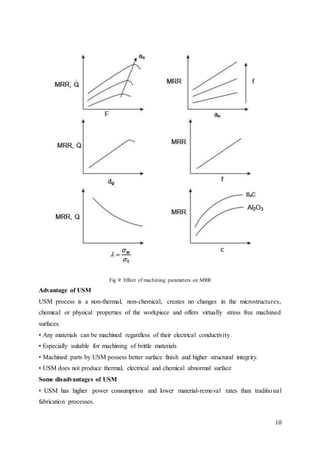
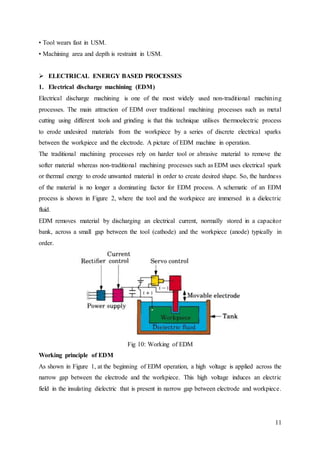
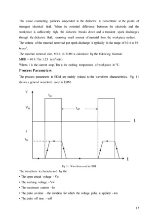
The document provides information on various non-conventional machining processes. It begins by defining non-traditional manufacturing processes as those that remove material using mechanical, thermal, electrical, or chemical energy without sharp cutting tools. Extremely hard materials are difficult to machine with traditional processes. The document then discusses several non-traditional processes in detail, including abrasive jet machining (AJM), ultrasonic machining (USM), electrical discharge machining (EDM), and their working principles and applications.
UNCONVENTIONAL MACHINING PROCESS CLASSIFICATION-MECHANICAL ENERGY METHODS-ELECTRICAL ENERGY METHODS-CHEMICAL ENERGY METHODS-ELECTRO CHEMICAL ENERGY METHODS-THERMALENERGY METHODS.
A tool that has a single point for cutting purpose is called single point cutting tool. It is generally used in the lathe machine, shaper machine etc. It is used to remove the materials from the workpiece.
This chapter aims to provide basic backgrounds of different types of machining processes and highlights on an understanding of important parameters which affects machining of metals with their chip removals.
Metal cutting or Machining is the process of producing workpiece by removing unwanted material from a block of metal. in the form of chips. This process is most important since almost all the products get their final shape and size by metal removal. either directly or indirectly.
The major drawback of the process is loss of material in the form of chips. In this chapter. we shall have a fundamental understanding of the basic metal process.
This is Part 2 Power point Presentation of Unconventional Machining Process. in this PPT consisting of
Abrasive Jet Machining
Water Jet Machining
Abrasive water jet machining
Ultrasonic machining process
Exactly i said about these PPT Fully covered in UNIT -2 Under the Anna university syllabus. in this presentation is most widely used for getting good knowledge about which above mentioned machining field, .....remaining units i will upload soon .... With Happiest moment i submit my materials to my students... Thank you ...
Wish you all the best for your successful carrier guys
Minimization of Material Removal Rate in Abrasive Jet Machining of Tempered G...paperpublications3
Abstract: Modern machining methods are also known as Non Traditional machining methods. These methods form a group of processes which removes excess material by various techniques involving mechanical, thermal, electrical, chemical energy or combination of these energies. There is no cutting of metal with the help of metallic tool having sharp cutting edge. The major reasons of development and popularity of the modern machining methods are listed below.
Need to machine newly developed metals and non-metals having some special properties like extremely high strength, high hardness and high toughness. A Materials poising the above mentioned properties are difficult to be machined by the Conventional machining methods.
Sometimes it is required to produce complex part geometries that cannot be easily produced by following conventional machining techniques .Non
Traditional machining methods also provide very good quality of surface finish, which may also be an encouragement of these methods. There can be a very long list of non-conventional machining methods. These methods can be classified as the basis of their base principle of working as given in the following section.
TQM is the integration of all functions and processes within an organization in order to achieve continuous improvement of the quality of goods and services. The goal is customer satisfaction.
Pressure Jet Systems Pvt. Ltd., a leading manufacturer of high pressure reciprocating triplex plunger pumps and complete systems, used for High Pressure Cleaning, Hydro Jetting, Hydro Blasting, Hydro static Pressure Test, Sewer Jetting, Fire Fighting, Misting-Fogging, Paint & Rust removal and many other industrial applications.
We manufacture pumps having pressure up to 1400 bar, flow rate up to 445 lpm and power up to 180 hp, supplying to corporate giants such as NTPC, BHEL, Reliance and many other.
Frame is a ladder shaped structure with two longitudinal rails/beams (Frame side members) and properly located many integrating and reinforcing cross members, which form the ladder structure that is used as the interface/platform between the power package and the body package in Automobiles.
EDR Group of Industries established in the year 1968 is dedicating to manufacturing of mechanical Seals and selling Systems, Centrifugal Pumps and Investment Castings.
Steelcast limited industrial training reportaman1312
Steelcast limited is an India-based company. The company is engaged in the business of steel casting . Its product include carbon steel , low alloy steel , high alloy steel , hadfield manganese steel , and other grade of wear and abrasion resistant steel casting produced by sand molding and shell moulding process . The Company caters to industries , such as earthmoving equipment manufacturing , heavy electrical equipment manufacturing , mining , minerals processing equipment manufacturers , valve manufacturers and general engineering equipment manufacturers.
Windsor machines are the India’s largest plastic processing machinery manufacturing and exporting company. Windsor machines have been manufacturing a complete range of plastic processing machinery for more than decades. It has collaboration with R.H. Windsor of U.K. In 1984 Klockner works of Germany made the company a part of its worldwide operation and renamed it Klockner
During mid- sixties the Co-operative sector in India was responsible for distribution of 70 per cent of fertilisers consumed in the country. This Sector had adequate infrastructure to distribute fertilisers but had no production facilities of its own and hence dependent on public/private Sectors for supplies. To overcome this lacuna and to bridge the demand supply gap in the country, a new cooperative society was conceived to specifically cater to the requirements of farmers. It was an unique venture in which the farmers of the country through their own Co-operative Societies created this new institution to safeguard their interests. The number of Co-operative Societies associated with IFFCO have risen from 57 in 1967 to 39,824 at present.
The flagship company of UCM Group, Mangalam Alloy Ltd., was established in 1989. It has weathered tough economic tides with its mat flying high. Mangalam Alloys Ltd., is a stainless steel melting, rolling, heat treatment, and bright unit bar unit having installed company of 1800T/M, 4000 T/M, 1000T/M, 300 T/M, respectively.
The emergence of Ambuja Cement, way back in the middle of the 20 century, coincides with the beginning of the industrial India. The consistent of Ambuja Cement since mid 20 century in setting up of dynamic Indian industry, in the process of building an economically an socially strong India is a well known and recognized fact and the countrymen consider Ambuja Organisation as a steadfast forerunner in the case of strong self reliant India.
THE CHALLENGE FOR THE 21. CENTURY Day by day we hear more disturbing news about the “Climate Change” that is happening all over the world. More and more people are getting seriously impacted by increasingly strong and more frequent hurricanes. We hear about unprecedented droughts in one area while there is severe flooding in another. People are forced to leave entire regions due to desertification of the land.
Fabrication is the processing of raw material or any semi finished product in the final shape by different methods such as welding, forming, sheet metal operations or casting. Solid Freeform Fabrication (SFF) is related to rapid prototype process.
Semiconductors are materials that have electrical conductivity between conductors such as most metals and nonconductors or insulators like ceramics. How much electricity a semiconductor can conduct depends on the material and its mixture content.
Semiconductors can be insulators at low temperatures and conductors at high temperatures. As they are used in the fabrication of electronic devices, semiconductors play an important role in our lives.
Laser Processing of Different materials and its application.aman1312
Presentation of laser application in different types of industry for material processing. Laser materials processing is done on various materials such as metals, non metals, ceramics, polymer materials.
Tool design for Non-Conventional Machining.aman1312
tool design parameter consideration for three non conventional machining process has been discussed. they are Ultrasonic machining, Electrochemical machining.
This presentation contain discription about Fine finishing process of complex shape material which cannot be finished by normal processess. three type of finishing process has been described they are Abrasive flow machining, MAgnetic Abrasive Finishing, Magneto Rheological abrasive finishing.
This presentation contain different design consideration for manufacturing of product such as design of Environment, Design for Assembly, Design for Disassembly, Design for Recyclabilities & remanufacture, Energy Effficieny, Environmental Regulatory, Important Acts
Industrial Training at Shahjalal Fertilizer Company Limited (SFCL)MdTanvirMahtab2
This presentation is about the working procedure of Shahjalal Fertilizer Company Limited (SFCL). A Govt. owned Company of Bangladesh Chemical Industries Corporation under Ministry of Industries.
About
Indigenized remote control interface card suitable for MAFI system CCR equipment. Compatible for IDM8000 CCR. Backplane mounted serial and TCP/Ethernet communication module for CCR remote access. IDM 8000 CCR remote control on serial and TCP protocol.
• Remote control: Parallel or serial interface.
• Compatible with MAFI CCR system.
• Compatible with IDM8000 CCR.
• Compatible with Backplane mount serial communication.
• Compatible with commercial and Defence aviation CCR system.
• Remote control system for accessing CCR and allied system over serial or TCP.
• Indigenized local Support/presence in India.
• Easy in configuration using DIP switches.
Technical Specifications
Indigenized remote control interface card suitable for MAFI system CCR equipment. Compatible for IDM8000 CCR. Backplane mounted serial and TCP/Ethernet communication module for CCR remote access. IDM 8000 CCR remote control on serial and TCP protocol.
Key Features
Indigenized remote control interface card suitable for MAFI system CCR equipment. Compatible for IDM8000 CCR. Backplane mounted serial and TCP/Ethernet communication module for CCR remote access. IDM 8000 CCR remote control on serial and TCP protocol.
• Remote control: Parallel or serial interface
• Compatible with MAFI CCR system
• Copatiable with IDM8000 CCR
• Compatible with Backplane mount serial communication.
• Compatible with commercial and Defence aviation CCR system.
• Remote control system for accessing CCR and allied system over serial or TCP.
• Indigenized local Support/presence in India.
Application
• Remote control: Parallel or serial interface.
• Compatible with MAFI CCR system.
• Compatible with IDM8000 CCR.
• Compatible with Backplane mount serial communication.
• Compatible with commercial and Defence aviation CCR system.
• Remote control system for accessing CCR and allied system over serial or TCP.
• Indigenized local Support/presence in India.
• Easy in configuration using DIP switches.
Democratizing Fuzzing at Scale by Abhishek Aryaabh.arya
Presented at NUS: Fuzzing and Software Security Summer School 2024
This keynote talks about the democratization of fuzzing at scale, highlighting the collaboration between open source communities, academia, and industry to advance the field of fuzzing. It delves into the history of fuzzing, the development of scalable fuzzing platforms, and the empowerment of community-driven research. The talk will further discuss recent advancements leveraging AI/ML and offer insights into the future evolution of the fuzzing landscape.
Saudi Arabia stands as a titan in the global energy landscape, renowned for its abundant oil and gas resources. It's the largest exporter of petroleum and holds some of the world's most significant reserves. Let's delve into the top 10 oil and gas projects shaping Saudi Arabia's energy future in 2024.
Vaccine management system project report documentation..pdfKamal Acharya
The Division of Vaccine and Immunization is facing increasing difficulty monitoring vaccines and other commodities distribution once they have been distributed from the national stores. With the introduction of new vaccines, more challenges have been anticipated with this additions posing serious threat to the already over strained vaccine supply chain system in Kenya.
Sachpazis:Terzaghi Bearing Capacity Estimation in simple terms with Calculati...Dr.Costas Sachpazis
Terzaghi's soil bearing capacity theory, developed by Karl Terzaghi, is a fundamental principle in geotechnical engineering used to determine the bearing capacity of shallow foundations. This theory provides a method to calculate the ultimate bearing capacity of soil, which is the maximum load per unit area that the soil can support without undergoing shear failure. The Calculation HTML Code included.
Hybrid optimization of pumped hydro system and solar- Engr. Abdul-Azeez.pdffxintegritypublishin
Advancements in technology unveil a myriad of electrical and electronic breakthroughs geared towards efficiently harnessing limited resources to meet human energy demands. The optimization of hybrid solar PV panels and pumped hydro energy supply systems plays a pivotal role in utilizing natural resources effectively. This initiative not only benefits humanity but also fosters environmental sustainability. The study investigated the design optimization of these hybrid systems, focusing on understanding solar radiation patterns, identifying geographical influences on solar radiation, formulating a mathematical model for system optimization, and determining the optimal configuration of PV panels and pumped hydro storage. Through a comparative analysis approach and eight weeks of data collection, the study addressed key research questions related to solar radiation patterns and optimal system design. The findings highlighted regions with heightened solar radiation levels, showcasing substantial potential for power generation and emphasizing the system's efficiency. Optimizing system design significantly boosted power generation, promoted renewable energy utilization, and enhanced energy storage capacity. The study underscored the benefits of optimizing hybrid solar PV panels and pumped hydro energy supply systems for sustainable energy usage. Optimizing the design of solar PV panels and pumped hydro energy supply systems as examined across diverse climatic conditions in a developing country, not only enhances power generation but also improves the integration of renewable energy sources and boosts energy storage capacities, particularly beneficial for less economically prosperous regions. Additionally, the study provides valuable insights for advancing energy research in economically viable areas. Recommendations included conducting site-specific assessments, utilizing advanced modeling tools, implementing regular maintenance protocols, and enhancing communication among system components.
Forklift Classes Overview by Intella PartsIntella Parts
Discover the different forklift classes and their specific applications. Learn how to choose the right forklift for your needs to ensure safety, efficiency, and compliance in your operations.
For more technical information, visit our website https://intellaparts.com
Water scarcity is the lack of fresh water resources to meet the standard water demand. There are two type of water scarcity. One is physical. The other is economic water scarcity.
1. 1
Objective:- A Comparative Study of Working principle and Applications of various Non-
Conventional machining Processes.
1. Introduction
Non-traditional manufacturing processes is defined as a group of processes that remove excess
material by various techniques involving Mechanical, Thermal, Electrical or Chemical energy
or combinations of these energies but do not use a sharp cutting tools as it needs to be used for
traditional manufacturing processes.
Extremely hard and brittle materials are difficult to machine by traditional machining processes
such as turning, drilling, shaping and milling. Non-traditional machining processes, also called
advanced manufacturing processes, are employed where traditional machining processes are
not feasible, satisfactory or economical due to special reasons as outlined below.
• Very hard fragile materials difficult to clamp for traditional machining
• When the work piece is too flexible or slender
• When the shape of the part is too complex
Several types of non-traditional machining processes have been developed to meet extra
required machining conditions. When these processes are employed properly, they offer many
advantages over non-traditional machining processes.
2. Material removal processes can be divided into two groups
1. Conventional Machining Processes
2. Unconventional Machining processes or Non-Traditional Manufacturing Processes
Conventional Machining Processes mostly remove material in the form of chips by applying
forces on the work material with a wedge shaped cutting tool that is harder than the work
material under machining condition.
The major characteristics of conventional machining are:
• Generally macroscopic chip formation by shear deformation.
• Material removal takes place due to application of cutting forces – energy domain can be
classified as mechanical.
• Cutting tool is harder than work piece at room temperature as well as under machining
conditions.
Non-conventional manufacturing processes is defined as a group of processes that remove
excess material by various techniques involving Mechanical, Thermal, Electrical or Chemical
energy or combinations of these energies but do not use a sharp cutting tools as it needs to be
used for traditional manufacturing processes.
2. 2
Material removal may occur with chip formation or even no chip formation may take place.
For example in AJM, chips are of microscopic size and in case of Electrochemical machining
material removal occurs due to electrochemical dissolution at atomic level.
2. NEED FOR UNCONVENTIONAL MACHINING PROCESSES
i. Extremely hard and brittle materials or Difficult to machine material are difficult to
machine by traditional machining processes.
ii. When the workpiece is too flexible or slender to support the cutting or grinding forces.
When the shape of the part is too complex.
4. CLASSIFICATION OF NON-CONVENTIONAL MACHINING PROCESSES:
A. Mechanical Processes B. Electrochemical Processes
i. Abrasive Jet Machining (AJM) i. Electrochemical Machining (ECM)
ii. Ultrasonic Machining (USM) ii. Electro Chemical Grinding (ECG)
iii. Water Jet Machining (WJM) iii. Electro Jet Drilling (EJD)
iv. Abrasive Water Jet Machining (AWJM)
C. Electro-Thermal Processes D. Chemical Processes
i. Electro-discharge machining (EDM) i. Chemical Milling (CHM)
ii. Laser Jet Machining (LJM) ii. Photochemical Milling (PCM)
iii. Electron Beam Machining (EBM)
MECHANICAL PROCESSES
1. ABRASIVE JET MACHINING (AJM)
In Abrasive Jet Machining (AJM), abrasive particles are made to impinge on the work material
at a high velocity. The jet of abrasive particles is carried by carrier gas or air. The high velocity
stream of abrasive is generated by converting the pressure energy of the carrier gas or air to its
kinetic energy and hence high velocity jet. The nozzle directs the abrasive jet in a controlled
manner onto the work material, so that the distance between the nozzle and the work piece and
the impingement angle can be set desirably. The high velocity abrasive particles remove the
material by micro-cutting action as well as brittle fracture of the work material. Fig. 1.1
schematically shows the material removal process.
3. 3
Fig 1: AJM
In AJM, generally, the abrasive particles of around 50 μm grit size would impinge on the work
material at velocity of 200 m/s from a nozzle of I.D. of 0.5 mm with a standoff distance of
around 2 mm. The kinetic energy of the abrasive particles would be sufficient to provide
material removal due to brittle fracture of the work piece or even micro cutting by the abrasives.
Working
In AJM, air is compressed in an air compressor and compressed air at a pressure of around 5
bar is used as the carrier gas as shown in Fig. 1.2. Fig. 1.2 Also shows the other major parts of
the AJM system. Gases like CO2, N2 can also be used as carrier gas which may directly be
issued from a gas cylinder. Generally oxygen is not used as a carrier gas.
Fig 2: AJM System
The carrier gas is first passed through a pressure regulator to obtain the desired working
pressure. The gas is then passed through an air dryer to remove any residual water vapour. To
4. 4
remove any oil vapour or particulate contaminant the same is passed through a series of filters.
Then the carrier gas enters a closed chamber known as the mixing chamber. The abrasive
particles enter the chamber from a hopper through a metallic sieve. The sieve is constantly
vibrated by an electromagnetic shaker. The mass flow rate of abrasive (15 gm/min) entering
the chamber depends on the amplitude of vibration of the sieve and its frequency. The abrasive
particles are then carried by the carrier gas to the machining chamber via an electro- magnetic
on-off valve. The machining enclosure is essential to contain the abrasive and machined
particles in a safe and eco-friendly manner. The machining is carried out as high velocity (200
m/s) abrasive particles are issued from the nozzle onto a work piece traversing under the jet.
Process Parameters and Machining Characteristics
Abrasive: Material - Al2O3 / SiC / Glass
beads
Shape –Irregular / spherical
Size – 10~50 μm
Mass flow rate – 2 ~ 20 gm/min
Carrier gas: Composition – Air, CO 2, N 2
Density – Air ~ 1.3 kg/m3
Velocity – 500 ~ 700 m/s
Pressure – 2 ~ 10 bar
Flow rate – 5 ~ 30 lpm
Abrasive Jet: Velocity – 100 ~ 300 m/s
Mixing ratio – mass flow ratio of abrasive
to gas
Stand-off distance – 0.5 ~ 5 mm
Impingement Angle – 60 0 ~ 90 0
Nozzle: Material – WC
Diameter – (Internal) 0.2 ~ 0.8 mm
Life – 10 ~ 300 hours
The important machining characteristics in AJM are:
• The material removal rate (MRR) mm3/min or gm/min
• The machining accuracy
• The life of the nozzle
Applications
• For drilling holes of intricate shapes in hard and brittle materials
• For machining fragile, brittle and heat sensitive materials
• AJM can be used for drilling, cutting, deburring, cleaning and etching.
• Micro-machining of brittle materials
Limitations
• MRR is rather low (around ~ 15 mm3/min for machining glass)
• Abrasive particles tend to get embedded particularly if the work material is ductile
• Tapering occurs due to flaring of the jet
• Environmental load is rather high.
5. 5
Fig 3: Effect of process parameters MRR
2. ABRASIVE WATER-JET MACHINING (AWJM)
Abrasive water jet cutting is an extended version of water jet cutting; in which the water jet
contains abrasive particles such as silicon carbide or aluminium oxide in order to increase the
material removal rate above that of water jet machining. Almost any type of material ranging
from hard brittle materials such as ceramics, metals and glass to extremely soft materials such
as foam and rubbers can be cut by abrasive water jet cutting. The narrow cutting stream and
computer controlled movement enables this process to produce parts accurately and efficiently.
This machining process is especially ideal for cutting materials that cannot be cut by laser or
thermal cut. Metallic, non-metallic and advanced composite materials of various thicknesses
can be cut by this process. This process is particularly suitable for heat sensitive materials that
cannot be machined by processes that produce heat while machining.
The schematic of abrasive water jet cutting is shown in Figure 15 which is similar to water jet
cutting apart from some more features underneath the jewel; namely abrasive, guard and
mixing tube. In this process, high velocity water exiting the jewel creates a vacuum which
sucks abrasive from the abrasive line, which mixes with the water in the mixing tube to form a
high velocity beam of abrasives.
6. 6
Applications
Abrasive water jet cutting is highly used in aerospace, automotive and electronics industries.
In aerospace industries, parts such as
titanium bodies for military aircrafts, engine
components (aluminium, titanium, heat
resistant alloys), aluminium body parts and
interior cabin parts are made using abrasive
water jet cutting.
In automotive industries, parts like interior
trim (head liners, trunk liners, door panels)
and fibre glass body components and
bumpers are made by this process. Similarly,
in electronics industries, circuit boards and
cable stripping are made by abrasive water
jet cutting. Fig 4: AWJ Machining
Advantages of abrasive water jet cutting
• In most of the cases, no secondary
finishing required
• No cutter induced distortion
• Low cutting forces on workpieces
• Limited tooling requirements
• Little to no cutting burr
• Typical finish 125-250 microns
• Smaller kerf size reduces material
wastages
• No heat affected zone
• Localises structural changes
• No cutter induced metal contamination
• Eliminates thermal distortion
• No slag or cutting dross
• Precise, multi plane cutting of contours,
shapes, and bevels of any angle.
Limitations of abrasive water jet cutting
• Cannot drill flat bottom
• Cannot cut materials that degrades quickly with moisture
• Surface finish degrades at higher cut speeds which are frequently used for rough cut
The major disadvantages of abrasive water jet cutting are high capital cost and high noise levels
during operation.
7. 7
3. Ultrasonic Machining (USM)
USM is mechanical material removal process or an abrasive process used to erode holes or
cavities on hard or brittle workpiece by using shaped tools, high frequency mechanical motion
and an abrasive slurry. USM offers a solution to the expanding need for machining brittle
materials such as single crystals, glasses and polycrystalline ceramics, and increasing complex
operations to provide intricate shapes and workpiece profiles. It is therefore used extensively
in machining hard and brittle materials that are difficult to machine by traditional
manufacturing processes. The hard particles in slurry are accelerated toward the surface of the
workpiece by a tool oscillating at a frequency up to 100 KHz - through repeated abrasions, the
tool machines a cavity of a cross section identical to its own. A schematic representation of
USM is shown in Figure.
Fig 5: USM Machining Operation
In ultrasonic machining, a tool of desired shape vibrates at an ultrasonic frequency (19 ~ 25
kHz) with an amplitude of around 15 – 50 μm over the workpiece. Generally the tool is pressed
downward with a feed force, F. Between the tool and workpiece, the machining zone is flooded
with hard abrasive particles generally in the form of a water based slurry. As the tool vibrates
over the workpiece, the abrasive particles act as the indenters and indent both the work material
and the tool. The abrasive particles, as they indent, the work material, would remove the same,
particularly if the work material is brittle, due to crack initiation, propagation and brittle
fracture of the material. Hence, USM is mainly used for machining brittle materials {which are
poor conductors of electricity and thus cannot be processed by Electrochemical and Electro-
discharge machining (ECM and ED)}.
USM is primarily targeted for the machining of hard and brittle materials (dielectric or
conductive) such as boron carbide, ceramics, titanium carbides, rubies, quartz etc. USM is a
versatile machining process as far as properties of materials are concerned. This process is able
to effectively machine all materials whether they are electrically conductive or insulator.
8. 8
WORKING
The basic mechanical structure of an USM is very similar to a drill press. However, it has
additional features to carry out USM of brittle work material. The workpiece is mounted on a
vice, which can be located at the desired position under the tool using a 2 axis table. The table
can further be lowered or raised to accommodate work of different thickness. The typical
elements of an USM are,
1. Slurry delivery and return system
2. Feed mechanism to provide a
downward feed force on the tool
during machining
3. The transducer, which generates the
ultrasonic vibration
4. The horn or concentrator, which
mechanically amplifies the vibration
to the required amplitude of 15 – 50
μm and accommodates the tool at its tip. Fig 6: Schematic view of an Ultrasonic Machine
The ultrasonic vibrations are produced by the transducer. The transducer is driven by suitable
signal generator followed by power amplifier. The transducer for USM works on the following
principle
1. Piezoelectric effect 3. Magnetostrictive effect
2. Electrostrictive effect
Magnetostrictive transducers are most popular and robust amongst all. Fig. 7 shows a typical
magnetostrictive transducer along with horn. The horn or concentrator is a wave-guide, which
amplifies and concentrates the vibration to the tool from the transducer.
Fig 7: Working of horn as Mechanical amplifier of amplitude of vibration
9. 9
The horn or concentrator can be of different shape like
Fig 8: Different Horns used in USM
Process Parameters and their Effects.
During discussion and analysis as presented in the previous section, the process parameters
which govern the ultrasonic machining process have been identified and the same are listed
below along with material parameters
• Amplitude of vibration (ao) – 15 – 50 μm
• Frequency of vibration (f) – 19 – 25 kHz
• Feed force (F) – related to tool dimensions
• Feed pressure (p)
• Abrasive size – 15 μm – 150 μm
• Abrasive material – Al2O3, SiC, B4C,
Boronsilicarbide, Diamond
• Flow strength of work material
• Flow strength of the tool material
• Contact area of the tool – A
• Volume concentration of abrasive in water
slurry – C
• The machining tool must be selected to be
highly wear resistant, such as high-carbon
steels.
The abrasives (25-60 µm in dia.) in the (water-based, up to 40% solid volume) slurry includes:
Boron carbide, silicon carbide and aluminum oxide.
Applications
Used for machining hard and brittle metallic alloys, semiconductors, glass, ceramics,
carbides.
Used for machining round, square, irregular shaped holes and surface impressions.
Machining, wire drawing, punching or small blanking dies.
10. 10
Fig 9: Effect of machining parameters on MRR
Advantage of USM
USM process is a non-thermal, non-chemical, creates no changes in the microstructures,
chemical or physical properties of the workpiece and offers virtually stress free machined
surfaces.
• Any materials can be machined regardless of their electrical conductivity
• Especially suitable for machining of brittle materials
• Machined parts by USM possess better surface finish and higher structural integrity.
• USM does not produce thermal, electrical and chemical abnormal surface
Some disadvantages of USM
• USM has higher power consumption and lower material-removal rates than traditional
fabrication processes.
11. 11
• Tool wears fast in USM.
• Machining area and depth is restraint in USM.
ELECTRICAL ENERGY BASED PROCESSES
1. Electrical discharge machining (EDM)
Electrical discharge machining is one of the most widely used non-traditional machining
processes. The main attraction of EDM over traditional machining processes such as metal
cutting using different tools and grinding is that this technique utilises thermoelectric process
to erode undesired materials from the workpiece by a series of discrete electrical sparks
between the workpiece and the electrode. A picture of EDM machine in operation.
The traditional machining processes rely on harder tool or abrasive material to remove the
softer material whereas non-traditional machining processes such as EDM uses electrical spark
or thermal energy to erode unwanted material in order to create desired shape. So, the hardness
of the material is no longer a dominating factor for EDM process. A schematic of an EDM
process is shown in Figure 2, where the tool and the workpiece are immersed in a dielectric
fluid.
EDM removes material by discharging an electrical current, normally stored in a capacitor
bank, across a small gap between the tool (cathode) and the workpiece (anode) typically in
order.
Fig 10: Working of EDM
Working principle of EDM
As shown in Figure 1, at the beginning of EDM operation, a high voltage is applied across the
narrow gap between the electrode and the workpiece. This high voltage induces an electric
field in the insulating dielectric that is present in narrow gap between electrode and workpiece.
12. 12
This cause conducting particles suspended in the dielectric to concentrate at the points of
strongest electrical field. When the potential difference between the electrode and the
workpiece is sufficiently high, the dielectric breaks down and a transient spark discharges
through the dielectric fluid, removing small amount of material from the workpiece surface.
The volume of the material removed per spark discharge is typically in the range of 10-6 to 10-
6 mm3.
The material removal rate, MRR, in EDM is calculated by the following foumula:
MRR = 40 I / Tm 1.23 (cm3/min)
Where, I is the current amp, Tm is the melting temperature of workpiece in 0C.
Process Parameters
The process parameters in EDM are mainly related to the waveform characteristics. Fig. 11
shows a general waveform used in EDM.
Fig 11: Waveform used in EDM
The waveform is characterised by the
• The open circuit voltage - Vo
• The working voltage - Vw
• The maximum current - Io
• The pulse on time – the duration for which the voltage pulse is applied - ton
• The pulse off time – toff
13. 13
• The gap between the workpiece and the tool – spark gap - δ
• The polarity – straight polarity – tool (-ve)
• The dielectric medium
• External flushing through the spark gap
Application of EDM
The EDM process has the ability to machine hard, difficult-to-machine materials. Parts with
complex, precise and irregular shapes for forging, press tools, extrusion dies, difficult internal
shapes for aerospace and medical applications can be made by EDM process.
Advantages of EDM
The main advantages of DM are:
• By this process, materials of any hardness can be machined;
• No burrs are left in machined surface;
• One of the main advantages of this process is that thin and fragile/brittle components can
be machined without distortion;
Limitations of EDM
The main limitations of this process are:
• This process can only be employed in electrically conductive materials;
• Material removal rate is low and the process overall is slow compared to conventional
machining processes;
• Unwanted erosion and over cutting of material can occur;
• Rough surface finish when at high rates of material removal.
Dielectric fluids
Dielectric fluids used in EDM process are hydrocarbon oils, kerosene and deionised water. The
functions of the dielectric fluid are to:
• Act as an insulator between the tool and the workpiece.
• Act as coolant.
• Act as a flushing medium for the removal of the chips.
The electrodes for EDM process usually are made of graphite, brass, copper and copper-
tungsten alloys.
Design considerations for EDM process are as follows:
• Deep slots and narrow openings should be avoided.
• The surface smoothness value should not be specified too fine.
• Rough cut should be done by other machining process. Only finishing operation should be
done in this process as MRR for this process is low.
14. 14
CHEMICAL AND ELECTRO CHEMICAL ENERGY BASED PROCESSES
1. Electrochemical Machining (ECM)
Electrochemical machining (ECM) is a metal-removal process based on the principle of reverse
electroplating. In this process, particles travel from the anodic material (workpiece) toward the
cathodic material (machining tool). A current of electrolyte fluid carries away the deplated
material before it has a chance to reach the machining tool. The cavity produced is the female
mating image of the tool shape.
Similar to EDM, the workpiece hardness is not a factor, making ECM suitable for machining
difficult-to –machine materials. Difficult shapes can be made by this process on materials
regardless of their hardness. A schematic representation of ECM process is shown in Figure 8.
The ECM tool is positioned very close to the workpiece and a low voltage, high amperage DC
current is passed between the workpiece and electrode. Some of the shapes made by ECM
process is shown in Figure 9.
Fig 12: Principle of Electro Chemical Machining (ECM)
PROCESS
During ECM, there will be reactions occurring at the electrodes i.e. at the anode or workpiece
and at the cathode or the tool along with within the electrolyte. Let us take an example of
machining of low carbon steel which is primarily a ferrous alloy mainly containing iron. For
electrochemical machining of steel, generally a neutral salt solution of sodium chloride (NaCl)
is taken as the electrolyte. The electrolyte and water undergoes ionic dissociation as shown
below as potential difference is applied
NaCl ↔ Na+ + Cl-
H2O ↔ H + + (OH)
As the potential difference is applied between the work piece (anode) and the tool (cathode),
the positive ions move towards the tool and negative ions move towards the workpiece. Thus
15. 15
the hydrogen ions will take away electrons from the cathode (tool) and from hydrogen gas as:
2H + + 2e- = H2↑ at cathode.
Fig 13: Schematic representation of electro-chemical reactions
Similarly, the iron atoms will come out of the anode (work piece) as: Fe = Fe+ + + 2e
Within the electrolyte iron ions would combine with chloride ions to form iron chloride and
similarly sodium ions would combine with hydroxyl ions to form sodium hydroxide
Na + + OH- = NaOH
In practice FeCl2 and Fe(OH)2 would form and get precipitated in the form of sludge. In this
manner it can be noted that the work piece gets gradually machined and gets precipitated as the
sludge. Moreover there is not coating on the tool, only hydrogen gas evolves at the tool or
cathode. Fig. 2 depicts the electro-chemical reactions schematically. As the material removal
takes place due to atomic level dissociation, the machined surface is of excellent surface finish
and stress free.
The voltage is required to be applied for the electrochemical reaction to proceed at a steady
state. That voltage or potential difference is around 2 to 30 V. The applied potential difference,
however, also overcomes the following resistances or potential drops.
They are:
• The electrode potential
• The activation over potential
• Ohmic potential drop
• Concentration over potential
• Ohmic resistance of electrolyte
EQUIPMENT
The electrochemical machining system has the following modules:
• Power supply
• Electrolyte filtration and delivery system
• Tool feed system
• Working tank
Fig. 4 schematically shows an electrochemical drilling unit.
16. 16
Fig 14: Schematic diagram of an electrochemical drilling unit
Advantages of ECM
• The components are not subject to either thermal or mechanical stress.
• No tool wear during ECM process.
• Fragile parts can be machined easily as there is no stress involved.
• ECM deburring can debur difficult to access areas of parts.
• High surface finish (up to 25 µm in) can be achieved by ECM process.
• Complex geometrical shapes in high-strength materials particularly in the aerospace industry
for the mass production of turbine blades, jet-engine parts and nozzles can be machined
repeatedly and accurately.
• Deep holes can be made by this process.
Limitations of ECM
• ECM is not suitable to produce sharp square corners or flat bottoms because of the tendency
for the electrolyte to erode away sharp profiles.
• ECM can be applied to most metals but, due to the high equipment costs, is usually used
primarily for highly specialized applications.
Material removal rate, MRR, in ECM
MRR = C .I. h (cm3/min)
17. 17
C: specific (material) removal rate (e.g., 0.2052 cm3/amp-min for nickel);
I: current (amp);
h: current efficiency (90–100%).
The rates at which metal can electrochemically remove are in proportion to the current passed
through the electrolyte and the elapsed time for that operation. Many factors other than current
influence the rate of machining. These involve electrolyte type, rate of electrolyte flow, and
some other process conditions.
APPLICATION
Fig 14: Different applications of Electro Chemical Machining
THERMAL ENERGY BASED PROCESSES
1. Laser–Beam Machining (LBM)
Laser-beam machining is a thermal material-removal process that utilizes a high-energy,
coherent light beam to melt and vaporize particles on the surface of metallic and non-metallic
workpieces. Lasers can be used to cut, drill, weld and mark. LBM is particularly suitable for
making accurately placed holes. A schematic of laser beam machining is shown in Figure.
18. 18
Fig 15: LBM
Different types of lasers are available for manufacturing operations which are as follows:
• CO2 (pulsed or continuous wave): It is a gas laser that emits light in the infrared region. It
can provide up to 25 kW in continuous-wave mode.
• Nd:YAG: Neodymium-doped Yttrium-Aluminum-Garnet (Y3Al 5O12) laser is a solid- state
laser which can deliver light through a fibre-optic cable. It can provide up to 50 kW power in
pulsed mode and 1 kW in continuous-wave mode.
Ruby-laser or crystalline aluminium oxide or saphire is the most commonly used solid state
laser. Generally these lasers are fabricated in into rods having length about 150 mm. Their ends
are well furnished to close optical tolerances. Figure below shows a schematic view of laser
beam machining process.
A small amount of chromium oxide is added to dope the ruby crystal. A flash of high intensity
light , generally Xenon-filled flash lamp is used to pump the laser. To fire the xenon lamp a
large capacitor is required to be discharged through it and 250 to 1000 watts of electric power
is needed to do this. The intense radiation discharged from the lamp excites the fluorescent
impurity atoms (chromium atoms) and these atoms reaches a higher energy level. After passing
through a series of energy levels when the atoms fall back to original energy level , an intense
beam of visible light emission is observed. This beam is reflected back from the coated rod
ends and make more and more atoms excited and stimulated and return to ground level. A
stimulated avalanche of light is obtained which is transmitted through the coated part (~80%
reflective). This light which is highly coherent in time and space has a very narrow frequency
band, is highly in phase and quite parallel. If this light is focused in association with ordinary
lenses on the desired spot of the w/p, high energy density is gained which helps to melt and
vaporize the metal.
19. 19
Applications
LBM can make very accurate holes as small as 0.005 mm in refractory metals ceramics, and
composite material without warping the workpieces. This process is used widely for drilling.
Laser beam cutting (drilling)
• In drilling, energy transferred (e.g., via a Nd:YAG laser) into the workpiece melts the material
at the point of contact, which subsequently changes into a plasma and leaves the region.
• A gas jet (typically, oxygen) can further facilitate this phase transformation and departure of
material removed.
• Laser drilling should be targeted for hard materials and hole geometries that are difficult to
achieve with other methods.
A typical SEM micrograph hole drilled by laser beam machining process employed in making
a hole is shown in Figure 13.
Laser beam cutting (milling)
• A laser spot reflected onto the surface of a workpiece travels along a prescribed trajectory
and cuts into the material.
• Continuous-wave mode (CO 2) gas lasers are very suitable for laser cutting providing high-
average power, yielding high material-removal rates, and smooth cutting surfaces.
Advantage of laser cutting
• No limit to cutting path as the laser point can move any path.
• The process is stress less allowing very fragile materials to be laser cut without any support.
• Very hard and abrasive material can be cut.
• Sticky materials are also can be cut by this process.
• It is a cost effective and flexible process.
• High accuracy parts can be machined.
• No cutting lubricants required
• No tool wear
• Narrow heat effected zone
Limitations of laser cutting
• Uneconomic on high volumes compared to stamping
• Limitations on thickness due to taper
• High capital cost
• High maintenance cost
• Assist or cover gas required
20. 20
10. ELECTRON BEAM MACHINING (EBM)
Electron Beam Machining (EBM) and Laser Beam Machining (LBM) are thermal processes
considering the mechanisms of material removal. However electrical energy is used to generate
high-energy electrons in case of Electron Beam Machining (EBM) and high-energy coherent
photons in case of Laser Beam Machining (LBM). Thus these two processes are often classified
as electro-optical-thermal processes.
There are different jet or beam processes, namely Abrasive Jet, Water Jet etc. These two are
mechanical jet processes. There are also thermal jet or beams. A few are oxyacetylene flame,
welding arc, plasma flame etc. EBM as well as LBM are such thermal beam processes. Fig.
9.6.1 shows the variation in power density vs. the characteristic dimensions of different thermal
beam processes. Characteristic length is the diameter over which the beam or flame is active.
In case of oxyacetylene flame or welding arc, the characteristic length is in mm to tens of mm
and the power density is typically low. Electron Beam may have a characteristic length of tens
of microns to mm depending on degree of focusing of the beam. In case of defocused electron
beam, power density would be as low as 1 Watt/mm2. But in case of focused beam the same
can be increased to tens of kW/mm2. Similarly as can be seen in Fig. 16, laser beams can be
focused over a spot size of 10 – 100 μm with a power density as high as 1 MW/mm2. Electrical
discharge typically provides even higher power density with smaller spot size.
Fig 16: Variation in energy density with spot diameter of thermal beam processes
Process
Electron beam is generated in an electron beam gun. The construction and working principle
of the electron beam gun would be discussed in the next section. Electron beam gun provides
high velocity electrons over a very small spot size. Electron Beam Machining is required to be
21. 21
carried out in vacuum. Otherwise the electrons would interact with the air molecules, thus they
would loose their energy and cutting ability. Thus the workpiece to be machined is located
under the electron beam and is kept under vacuum. The high-energy focused electron beam is
made to impinge on the workpiece with a spot size of 10 – 100 μm. The kinetic energy of the
high velocity electrons is converted to heat energy as the electrons strike the work material.
Due to high power density instant melting and vaporisation starts and “melt – vaporisation”
front gradually progresses, as shown in Fig. 17. Finally the molten material, if any at the top of
the front, is expelled from the cutting zone by the high vapour pressure at the lower part. Unlike
in Electron Beam Welding, the gun in EBM is used in pulsed mode. Holes can be drilled in
thin sheets using a single pulse. For thicker plates, multiple pulses would be required. Electron
beam can also be manoeuvred using the electromagnetic deflection coils for drilling holes of
any shape.
Equipment
Fig. 17, shows the schematic representation of an electron beam gun, which is the heart of any
electron beam machining facility. The basic functions of any electron beam gun are to generate
free electrons at the cathode, accelerate them to a sufficiently high velocity and to focus them
over a small spot size. Further, the beam
needs to be manoeuvred if required by the
gun. The cathode as can be seen in Fig.
9.6.3 is generally made of tungsten or
tantalum. Such cathode filaments are
heated, often inductively, to a temperature
of around 25000C. Such heating leads to
thermo-ionic emission of electrons, which
is further enhanced by maintaining very
low vacuum within the chamber of the
electron beam gun. Moreover, this cathode
cartridge is highly negatively biased so
that the thermo-ionic electrons are
strongly repelled away form the cathode.
This cathode is often in the form of a
cartridge so that it can be changed very
quickly to reduce down time in case of failure. Fig 17: Mechanismof Material Removal
22. 22
Parameters
The process parameters, which directly affect the machining characteristics in Electron Beam
Machining, are:
• The accelerating voltage
• The beam current
• Pulse duration
• Energy per pulse
• Power per pulse
• Lens current
• Spot size
• Power density
ADVANTAGES OF EBM:
Large depth-to-width ratio of material penetrated by the beam with applications of very fine
hole drilling becoming feasible
There is a minimum number of pulses ne associated with an optimum accelerating voltage. In
practice the number of pulses to produce a given hole depth is usually found to decrease with
increase in accelerating voltage.
CHEMICAL PROCESSES
1. Chemical Machining
Chemical machining (CHM) process is a controlled chemical dissolution (CD) of a workpiece
material by contact with strong reagent (etchant). Special coatings called maskants protect
areas from which the metal is not to be machined. It is one of the non-conventional machining
processes. The advancement of technology causes to the development of many hard-to-
machine materials: stainless steel, super alloys, ceramics, refractories and fiber-reinforced
composites due to their high hardness, strength, brittleness, toughness and low machinability
properties. Sometimes, the machined components require high surface finish and dimensional
accuracy, complicated shape and special size, which cannot be achieved by the conventional
machining processes. Moreover, the rise in temperature and the residual stresses generated in
the workpiece due to traditional machining processes may not be acceptable. These
requirements have led to the development of non- traditional machining (NTM) processes. In
these processes, the conventional cutting tools which are not employed. Instead, energy in its
direct form is utilized. Chemical energy is used in chemical machining. This process is the
precision contouring of metal into any size, shape or form without the use of physical force, by
a controlled chemical reaction. Material is removed by microscopic electrochemical cell action,
as occurs in corrosion or chemical dissolution of a metal.
23. 23
This controlled chemical dissolution will simultaneously etch all exposed surfaces even though
the penetration rates of the etch may be only 0.0005–0.0030 in./min. The basic process takes
many forms: chemical milling of pockets, contours, overall metal removal, chemical blanking
for etching through thin sheets; photochemical machining (PCM) for etching by using of
photosensitive resists in microelectronics; chemical or electrochemical polishing where weak
chemical reagents are used (sometimes with remote electric assist) for polishing or deburring
and chemical jet machining where a single chemically active jet is used.
Chemical machining offers virtually unlimited scope for engineering and design ingenuity, to
gain the most from its unique characteristics, chemical machining should be approached with
the idea that this industrial tool can do jobs not practical or possible with any other metal
working methods. Chemical machining will likely prove to be of considerable value in the
solution of problems that are constantly arising as the result of the introduction of new
materials.
In comparison with other machining processes, chemical machining has many advantages, but
with some limitations. The most important advantages are: weight reduction is possible on
complex contours that are difficult to machine using conventional methods; decorative finishes
and extensive thin-web areas are possible to be machined; CHM does have low scrap rates (3
percent); no burrs are formed; no stress is introduced to the workpiece, which minimizes the
part distortion and makes machining of delicate parts possible; a continuous taper on contoured
sections is achievable; the capital cost of equipment, used for machining large components, is
relatively low; small thickness of metal can be removed; the good surface quality in addition
to the absence of burrs eliminate the need for finishing operations.
The limitations of CHM are: Handling and disposal of chemicals can be troublesome; hand
masking, scribing, and stripping can be time consuming, repetitive, and tedious and design
changes can be implemented quickly; metallurgical homogeneous surfaces are required for best
results; slower process, very low MRR so high cost of operation; deep narrow cuts are difficult
to produce; difficult to get sharp corner; hydrogen pickup and intergranular attack are a problem
with some materials; complex designs become expensive; simultaneous material removal, from
all surfaces, improves productivity and reduces wrapping; the straightness of the walls is
subjected to fillet and undercutting limitations; difficult to chemically machine thick material
(limit is depended on workpiece material, but the thickness should be around maximum
(10mm); porous materials and part designs that have deep, narrow cavities or folded-metal
seams should be avoided.
24. 24
Applications of CHM
Nontraditional machining processes are widely used to manufacture geometrically complex
and precision parts for aerospace, electronics and automotive and many other industries. There
are different geometrically designed parts, such as deep internal cavities, miniaturized
microelectronics and nontraditional machining processes may only produce fine quality
components. All the common metals including aluminum, copper, zinc, steel, lead, and nickel
can be chemically machined. Many exotic metals such as titanium, molybdenum, and
zirconium, as well as nonmetallic materials including glass, ceramics, and some plastics, can
also be used with the process. CHM applications range from large aluminum alloy airplane
wing parts to minute integrated circuit chips. The practical depth of cut ranges between 2.54 to
12.27 mm. Shallow cuts in large thin sheets are of the most popular application especially for
weight reduction of aerospace components. Multiple designs can be machined from the same
sheet at the same time. CHM is used to thin out walls, webs, and ribs of parts that have been
produced by forging, casting, or sheet metal forming.
Conclusion:
In the latest field of technology respect to welding and machining, plasma arc welding and
machining have a huge success. Due to its improved weld quality and increased weld output it
is been used for precision welding of surgical instruments, to automatic repair of jet engine
blades to the manual welding for repair of components in the tool, die and mold industry. But
due to its high equipment expense and high production of ozone, it’s been outnumbered by
other advance welding equipment like laser beam welding and electro beam welding.