Downloaded 1,561 times


![CATCHER
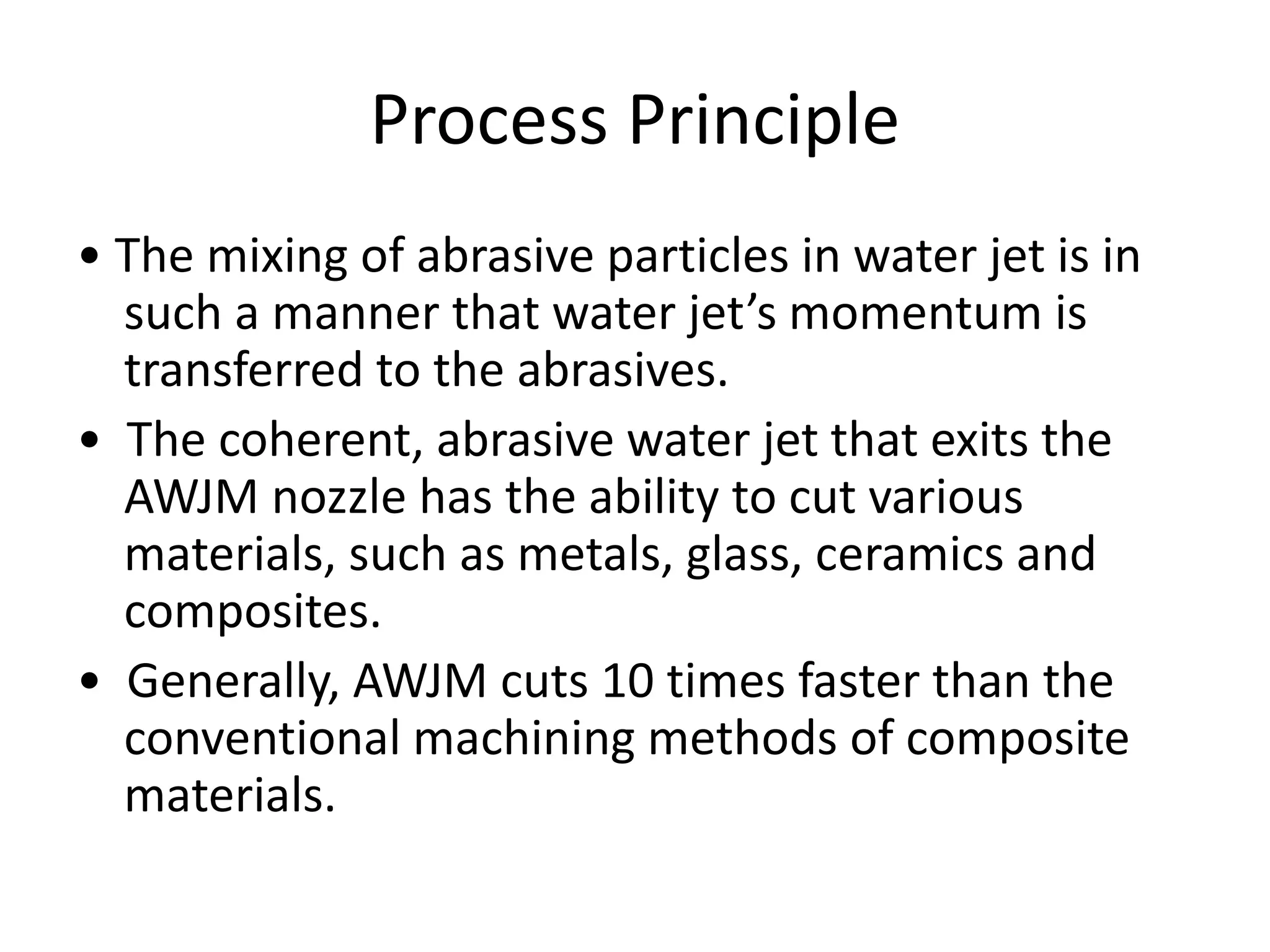
• “Catcher” is used to absorb the residual energy of the AWJ
and dissipate the same.
• Acts as a reservoir for collecting the machining debris
entrained in the water jet.
• Moreover, it reduces the noise levels [105 decibels (dB)]
associated with the reduction in the velocity of the water
jet from Mach 3 to subsonic levels
• Catcher is of two types
(a)Pocket type: The catcher basin travels along the jet
(along X&Y) .
(b)Line type :The catcher basin travels along one axis and
its length covers the entire width of the other
axis of the CNC table.](https://image.slidesharecdn.com/awjm-170119151444/75/Abrasive-water-jet-machining-38-2048.jpg)


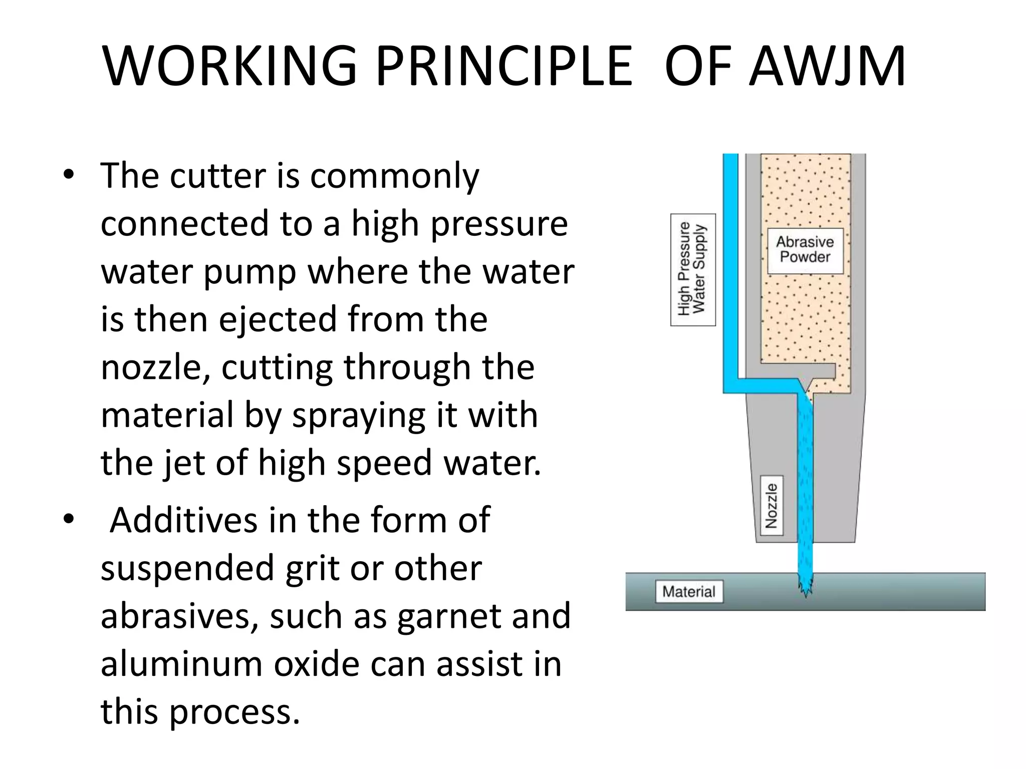
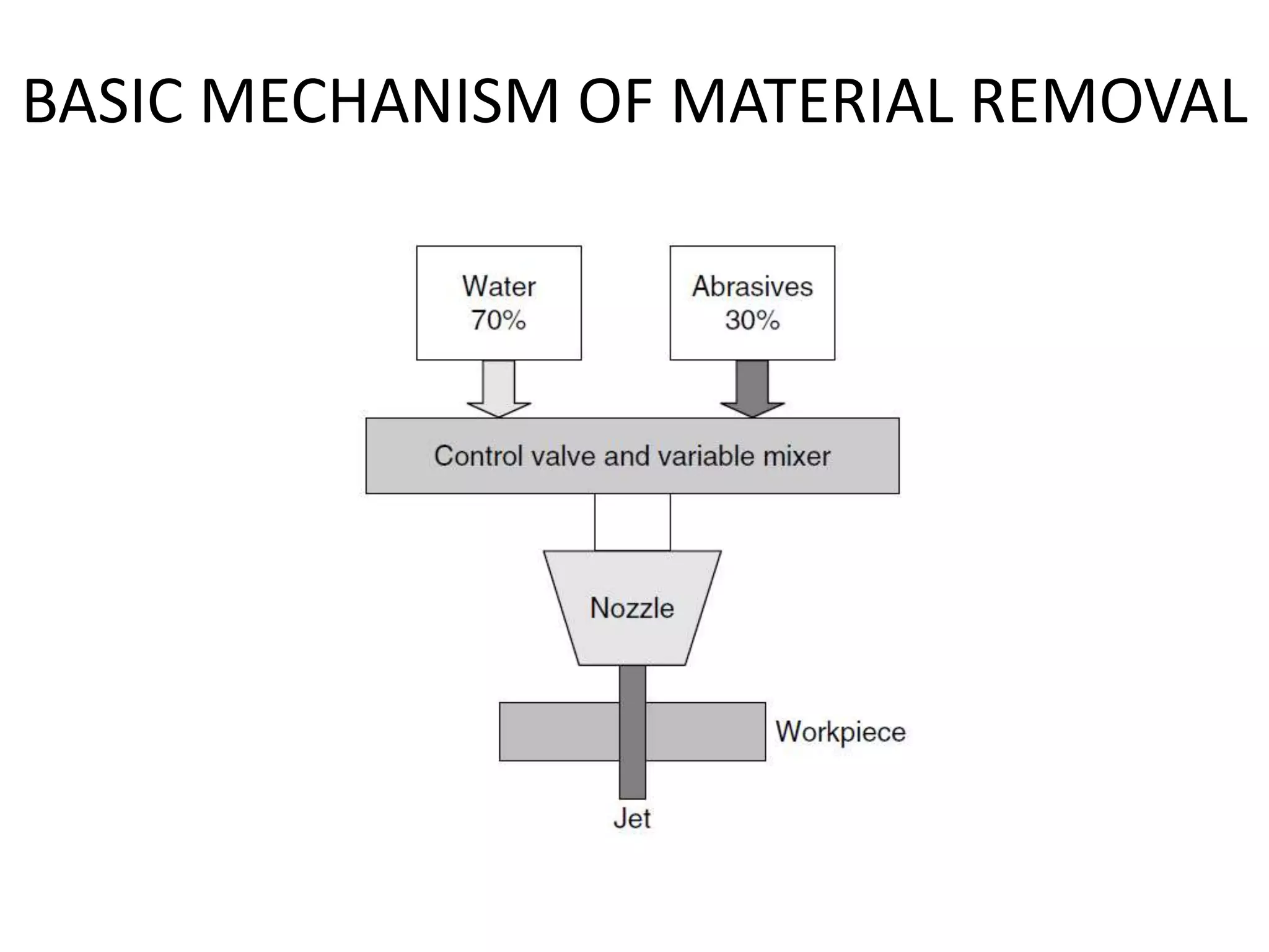
This document provides an overview of abrasive water jet machining (AWJM). It begins with an introduction that defines AWJM as a non-traditional machining process that uses the mechanical energy of water and abrasives for material removal. The working principle and basic mechanism of material removal are then described. Key aspects of AWJM equipment and processes are discussed, including the pumping system, abrasive feed system, nozzle, process parameters like water pressure and abrasive flow rate, and applications of the technique. Advantages include the ability to machine many materials without thermal damage but disadvantages include relatively low machining speeds.


