This document provides an introduction to abrasive jet machining (AJM), a type of non-traditional machining. It explains that AJM involves removing material from the workpiece through the impingement of high-velocity abrasive particles propelled by a gas. The key process parameters that control machining characteristics are described, including the abrasive material, gas used, nozzle design and stand-off distance. Advantages of AJM include obtaining a high surface finish, causing little damage, and enabling machining of heat-sensitive materials. Disadvantages are its lower material removal rate and difficulty achieving accuracy and straight holes.

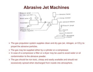
![The Gas
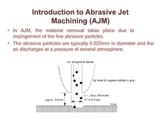
The AJM unit normally operates at a pressure of 0.2-1.0 N/mm2 .
The composition of gas and a high velocity has a significant impact on the
MRR even if the mixing ratio is not changed.
The Nozzle
The nozzle is one of the most vital elements controlling the process
characteristics.
The nozzle material should be hard to avoid any significant wear due to the
flowing abrasive. [Normally WC (avg. life: 12-30 hrs.) or Sapphire (Appr. =
300 hrs.) are used]
For a normal operation the cross-sectional area of the orifice can be either
circular or rectangular and between 0.05- 0.2mm2 .](https://image.slidesharecdn.com/notes-1-230827142657-8b652c37/85/Notes-1-pptx-15-320.jpg)


![Abrasive_Jet_Machine[1] .pdf](https://cdn.slidesharecdn.com/ss_thumbnails/abrasivejetmachine1-230106143105-297b109a-thumbnail.jpg?width=640&height=640&fit=bounds)


