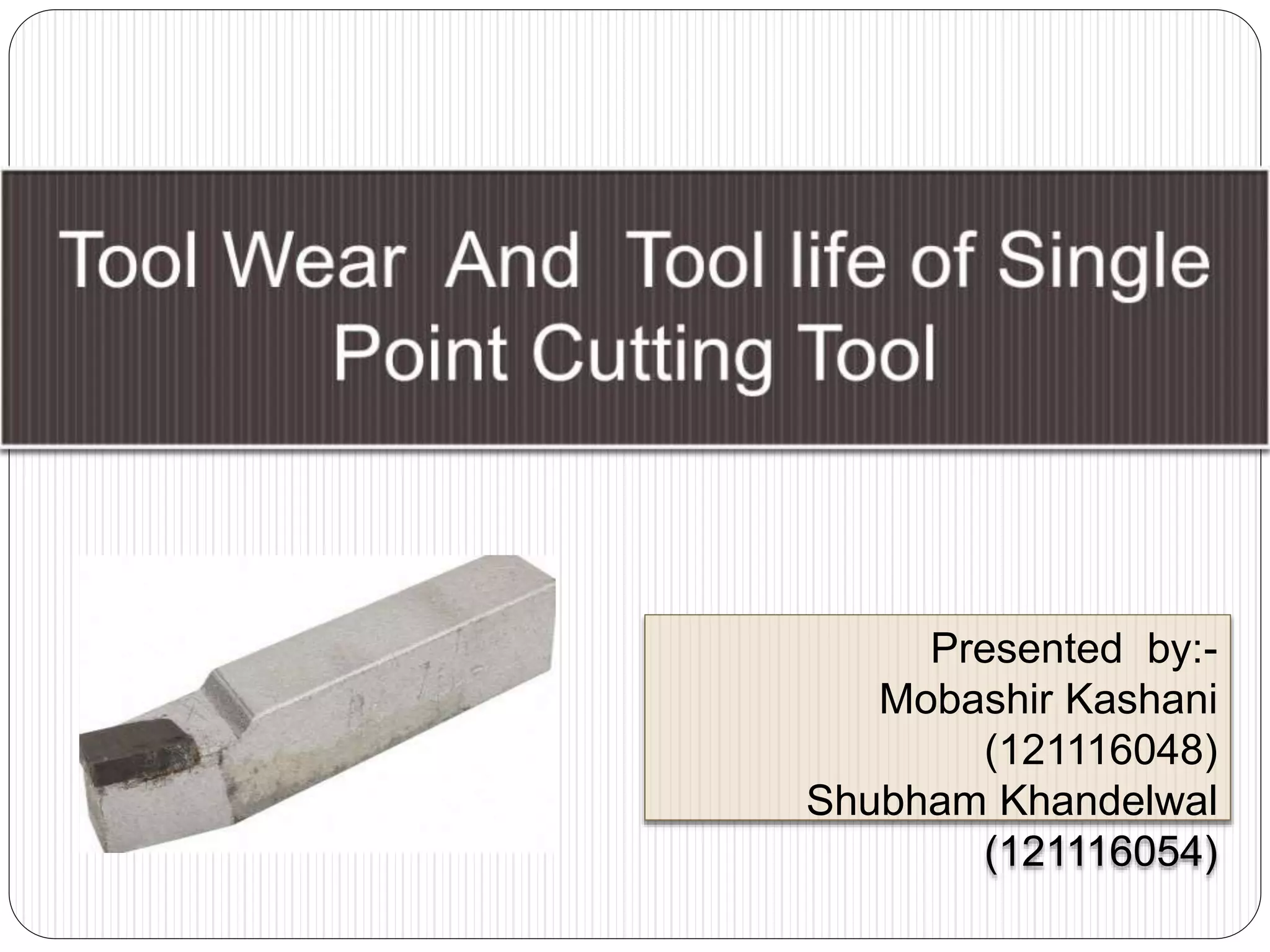
Presented by:-
Mobashir Kashani
(121116048)
Shubham Khandelwal
(121116054)
Tool Life
 Useful cutting life of tool expressed in time
 Time period measured from start of cut to failure
of the tool
 Time period between two consecutive
resharpenings or replacements.
Ways of measuring tool life
 No. of pieces of work machined
 Total volume of material removed
 Total length of cut.
 Limiting value of surface finish
 Increase in cutting forces
 Dimensional accuracy
 Overheating and fuming
 Presence of chatter
Modes of tool failure
1. Temperature failure
a. Plastic deformation of Cutting Edge (CE) due to
high temp
b. Cracking at the CE due to thermal stresses.
2. Rupture of the tool point
a. Chipping of tool edge due to mechanical impact
b. Crumbling of CE due to Built up Edge (BUE)
3. Gradual wear at tool point
a. Flank wear
b. Crater wear
Tool wear
 Tool wear causes the tool to lose its original
shape- ineffective cutting
 Tool needs to be resharpened
Causes of Tool Wear
1. Attrition wear
2. Diffusion wear
3. Abrasive wear
4. Electrochemical wear
5. Chemical wear
6. Plastic deformation
7. Thermal cracking
Attrition wear
 At low cutting speeds
 Flow of material past cutting edge is irregular and
less stream lined
 BUE formed and discontinuous contact with the
tool
 Fragments of tool are torn from the tool surface
intermittently
 High
 Slow and interrupted cutting
 Presence of vibrations
 Found in carbide tools at low cutting speeds
Diffusion wear
 Diffusion of metal & carbon atoms from the tool
surface into the w/p & chip.
 Due to
 High temp
 High pressure
 Rapid flow of chip & w/p past the tool
 Diffusion rate depends on the metallurgical
relationship
 Significant in carbide tools.
Abrasive wear
 Due to
 Presence of hard materials in w/p material.
 Strain hardening induced in the chip & w/p due to
plastic deformation.
 Contributes to flank wear
 Effect can be reduced by fine grain size of the
tool & lower percentage of cobalt
Electrochemical wear
 When ions are passed b/w tool & w/p
 Oxidation of the tool surface
 Break down of tool material @ chip tool interface
Chemical wear
 Interaction b/w tool and work material
 Plastics with carbide tools
 Cutting fluid
Plastic Deformation
 When high compressive stresses acts on tool
rake face- tool deformed downways – reduces
relief angle
 Modifies tool geometry and accelerates other
wear processes
Thermal cracking
 Due to cyclic thermal stresses at cutting edge
 Comb cracks
 Transverse cracks
 Chipping of tool
Geometry of tool wear
 Flank wear (edge wear)
 Crater wear (face wear)
Flank Wear
 Tool slides over the surface of the work piece and
friction is developed
 Due to Friction and abrasion.
 Adhesion between work piece & tool- BUE
 Starts at CE and starts widening along the
clearance face
 Independent of cutting conditions and tool / work
piece materials
 Brittle and discontinuous chip
 Increases as speed is increased.
 Primary stage rapid
wear due to very high
stress at tool point
 Wear rate is more or
less linear in the
secondary stage
 Tertiary stage wear
rate increases rapidly
resulting in
catastrophic failure.
Crater wear
 Direct contact of tool and w/p
 Forms cavity
 Ductile materials – continuous chips
 Initiates rapid rupture near to nose
 Leads to
 weakening of the tool
 Increase in cutting temp
 Cutting forces & friction
Measurement of tool life
 Time for Total destruction in case of HSS or time
to produce 0.75 mm wear for carbide tools
 Tool life expressed by Taylor’s eqn
 VTb = C
 V = cutting speed in cm/min
 T= tool life in min
 b= const= 0.1 for HSS
 C= 50 for HSS
 Cemented carbide : b=0.125, C=100
 Tool life expressed in volume of metal removed
 L = TVfd
Measurement of tool life
 Diamond Indentor technique
 Radioactive techniques
 Test at elevated cutting speeds
 Facing tests
 Test with low wear criterion
Factors affecting tool life
1. Cutting speed
2. Physical properties of w/p
3. Area of cut
4. Ratio of feed to depth of cut
5. Shape and angles of tool
6. Tool material and its heat treatment
7. Nature and quantity of coolants
8. Rigidity of tool and wp

Tool Wear and Tool Life

  • 1.
  • 2.
    Tool Life  Usefulcutting life of tool expressed in time  Time period measured from start of cut to failure of the tool  Time period between two consecutive resharpenings or replacements.
  • 3.
    Ways of measuringtool life  No. of pieces of work machined  Total volume of material removed  Total length of cut.  Limiting value of surface finish  Increase in cutting forces  Dimensional accuracy  Overheating and fuming  Presence of chatter
  • 4.
    Modes of toolfailure 1. Temperature failure a. Plastic deformation of Cutting Edge (CE) due to high temp b. Cracking at the CE due to thermal stresses. 2. Rupture of the tool point a. Chipping of tool edge due to mechanical impact b. Crumbling of CE due to Built up Edge (BUE) 3. Gradual wear at tool point a. Flank wear b. Crater wear
  • 5.
    Tool wear  Toolwear causes the tool to lose its original shape- ineffective cutting  Tool needs to be resharpened
  • 6.
    Causes of ToolWear 1. Attrition wear 2. Diffusion wear 3. Abrasive wear 4. Electrochemical wear 5. Chemical wear 6. Plastic deformation 7. Thermal cracking
  • 7.
    Attrition wear  Atlow cutting speeds  Flow of material past cutting edge is irregular and less stream lined  BUE formed and discontinuous contact with the tool  Fragments of tool are torn from the tool surface intermittently  High  Slow and interrupted cutting  Presence of vibrations  Found in carbide tools at low cutting speeds
  • 8.
    Diffusion wear  Diffusionof metal & carbon atoms from the tool surface into the w/p & chip.  Due to  High temp  High pressure  Rapid flow of chip & w/p past the tool  Diffusion rate depends on the metallurgical relationship  Significant in carbide tools.
  • 9.
    Abrasive wear  Dueto  Presence of hard materials in w/p material.  Strain hardening induced in the chip & w/p due to plastic deformation.  Contributes to flank wear  Effect can be reduced by fine grain size of the tool & lower percentage of cobalt
  • 10.
    Electrochemical wear  Whenions are passed b/w tool & w/p  Oxidation of the tool surface  Break down of tool material @ chip tool interface
  • 11.
    Chemical wear  Interactionb/w tool and work material  Plastics with carbide tools  Cutting fluid
  • 12.
    Plastic Deformation  Whenhigh compressive stresses acts on tool rake face- tool deformed downways – reduces relief angle  Modifies tool geometry and accelerates other wear processes
  • 13.
    Thermal cracking  Dueto cyclic thermal stresses at cutting edge  Comb cracks  Transverse cracks  Chipping of tool
  • 14.
    Geometry of toolwear  Flank wear (edge wear)  Crater wear (face wear)
  • 15.
    Flank Wear  Toolslides over the surface of the work piece and friction is developed  Due to Friction and abrasion.  Adhesion between work piece & tool- BUE  Starts at CE and starts widening along the clearance face  Independent of cutting conditions and tool / work piece materials  Brittle and discontinuous chip  Increases as speed is increased.
  • 16.
     Primary stagerapid wear due to very high stress at tool point  Wear rate is more or less linear in the secondary stage  Tertiary stage wear rate increases rapidly resulting in catastrophic failure.
  • 17.
    Crater wear  Directcontact of tool and w/p  Forms cavity  Ductile materials – continuous chips  Initiates rapid rupture near to nose  Leads to  weakening of the tool  Increase in cutting temp  Cutting forces & friction
  • 18.
    Measurement of toollife  Time for Total destruction in case of HSS or time to produce 0.75 mm wear for carbide tools  Tool life expressed by Taylor’s eqn  VTb = C  V = cutting speed in cm/min  T= tool life in min  b= const= 0.1 for HSS  C= 50 for HSS  Cemented carbide : b=0.125, C=100  Tool life expressed in volume of metal removed  L = TVfd
  • 19.
    Measurement of toollife  Diamond Indentor technique  Radioactive techniques  Test at elevated cutting speeds  Facing tests  Test with low wear criterion
  • 20.
    Factors affecting toollife 1. Cutting speed 2. Physical properties of w/p 3. Area of cut 4. Ratio of feed to depth of cut 5. Shape and angles of tool 6. Tool material and its heat treatment 7. Nature and quantity of coolants 8. Rigidity of tool and wp