This document discusses tool wear in machining. It defines tool wear as the gradual failure of cutting tools due to regular operation. There are three main modes of tool failure: fracture failure from excessive forces, temperature failure if the tool gets too hot, and gradual wear over time. Factors that influence the rate of tool wear include the tool material, workpiece material, cutting dimensions/speed, tool geometry, temperature, and cutting fluid used. The main types of tool wear are crater wear on the rake face, flank wear along the tool edge, and corner or nose wear which shortens the cutting edge. Controlling tool wear involves reducing the cutting temperature through fluids/lubricants or advanced tool materials.
Honing is an abrasive machining process that produces a precision surface on a metal work piece by scrubbing an abrasive stone against it along a controlled path.
Honing is primarily used to improve the geometric form of a surface, but may also improve the surface texture.
This presentation describes the cylindrical grinding process and types of operations and machines in this process, which is why useful topic B.Tech mechanical of fourth sem students. This explains about the overview on the external cylindrical grinding process.
Theory of Metal cutting - Principles of Metal cutting, orthogonal and oblique cutting, Merchant circle diagram, cutting forces, power requirements, Economics of machining,problems
This presentation gives details on Heat Generation in Metal Cutting tool. There are three zones of heat generation where heat generation equation is also derived by analytical method.
PREDICTION AND CONTROL OF LATHE MACHINE TOOL VIBRATION BY USING PASSIVE DAMPING ijiert bestjournal
In machining operation,the quality of surface finish is an important requirement for many turned work- pieces. Thus the choice of optimized cutting parameters is very important for controlling the required surface quality. The focus of present experimental study is to opt imize the cutting parameters using two performance measures,machine tool vibration and work-piece surface roughness The prediction and control of vibration between the tool and work piece is important as guidel ine to the machine tools user for an optimal selection of depth of cut,cutting speed,tool feed rate to minimize the vibration. In machining operation there are different variables deleterious the desire d result. In this process the behavior of machine tool,cutting tool life and cutting tool vibration are the complex pheno menon which influences on the dimensional precision of the components to be machined,the cutting tool vibrations are mainly influenced by cutting parameters like cutting speed,depth of cut and tool feed rate. In this project work,CNC lathe cutting tool vibrations are controlled the tool holder is supported wit h and without damping pad. To increase the accuracy of experiments,Taguchi L9 experimental design me thod has used in this experiment. Experimental result are validate with analysis of variance (ANOVA) and regression analysis to identify the influences of the different cutting parameter on the vibra tion of cutting tool.
Experimental Investigation of Effect of Tool Length on Surface Roughness duri...IOSR Journals
: In the turning operation, vibration is a frequent problem, which affects the result of the machining
and in particular the surface finish. Tool life is also influenced by vibrations. Severe acoustic noise in the
working environment frequently results as a dynamic motion between the cutting tool and the work piece. In all
cutting operations like turning, boring and milling vibrations are induced due to deformation of the work piece.
In the turning process, the importance of machining parameter choice is increased, as it controls the surface
quality required. Tool overhang is a cutting tool parameter that has not been investigated in as much detail as
some of the better known ones. It is appropriate to keep the tool overhang as short as possible; however, a
longer tool overhang may be required depending on the geometry of the work piece and when using the holeturning
process in particular. In this study, we investigate the effects of changes in the tool overhang in the
external turning process on both the surface quality of the work piece and tool wear. For this purpose, we used
work pieces of AISI 1050 material with diameters of 20, 30, and 40 mm; and the surface roughness of the work
piece were determined through experiments using constant cutting speed and feed rates with different depth of
cuts (DOCs) and tool overhangs. We observed that the effect of the DOC on the surface roughness is negligible,
but tool overhang is more important. The deflection of the cutting tool increases with tool overhang. Two
different analytical methods were compared to determine the dependence of tool deflection on the tool
overhang. Also, the real tool deflection values were determined using a comparator. We observed that the tool
deflection values were quite compatible with the tool deflection results obtained using the second analytical
method.
Theory of metal cutting MG University(S8 Production Notes)Denny John
Theory of metal cutting MG University(S8 Production Notes)
Scenario of manufacturing process – Deformation of metals,
Schmid’s law (review only) – Performance and process parameters – single point cutting
tool nomenclature - attributes of each tool nomenclature - attributes of feed and tool
signature on surface roughness obtainable, role of surface roughness on crack initiation -
Oblique and orthogonal cutting – Mechanism of metal removal - Primary and secondary
deformation shear zones - Mechanism of chip formation, card model, types of chip,
curling of chips, flow lines in a chip, BUE, chip breakers, chip thickness ratio –
Mechanism of orthogonal cutting: Thin zone and thick zone, Merchant’s analysis – shear
angle relationship, Lee and Shaffer`s relationship, simple problems – Friction process in
metal cutting: nature of sliding friction, columb`s law, adhesion theory, ploughing, sublayer
flow – Empirical determination of force component.
CFD Simulation of By-pass Flow in a HRSG module by R&R Consult.pptxR&R Consult
CFD analysis is incredibly effective at solving mysteries and improving the performance of complex systems!
Here's a great example: At a large natural gas-fired power plant, where they use waste heat to generate steam and energy, they were puzzled that their boiler wasn't producing as much steam as expected.
R&R and Tetra Engineering Group Inc. were asked to solve the issue with reduced steam production.
An inspection had shown that a significant amount of hot flue gas was bypassing the boiler tubes, where the heat was supposed to be transferred.
R&R Consult conducted a CFD analysis, which revealed that 6.3% of the flue gas was bypassing the boiler tubes without transferring heat. The analysis also showed that the flue gas was instead being directed along the sides of the boiler and between the modules that were supposed to capture the heat. This was the cause of the reduced performance.
Based on our results, Tetra Engineering installed covering plates to reduce the bypass flow. This improved the boiler's performance and increased electricity production.
It is always satisfying when we can help solve complex challenges like this. Do your systems also need a check-up or optimization? Give us a call!
Work done in cooperation with James Malloy and David Moelling from Tetra Engineering.
More examples of our work https://www.r-r-consult.dk/en/cases-en/
Hierarchical Digital Twin of a Naval Power SystemKerry Sado
A hierarchical digital twin of a Naval DC power system has been developed and experimentally verified. Similar to other state-of-the-art digital twins, this technology creates a digital replica of the physical system executed in real-time or faster, which can modify hardware controls. However, its advantage stems from distributing computational efforts by utilizing a hierarchical structure composed of lower-level digital twin blocks and a higher-level system digital twin. Each digital twin block is associated with a physical subsystem of the hardware and communicates with a singular system digital twin, which creates a system-level response. By extracting information from each level of the hierarchy, power system controls of the hardware were reconfigured autonomously. This hierarchical digital twin development offers several advantages over other digital twins, particularly in the field of naval power systems. The hierarchical structure allows for greater computational efficiency and scalability while the ability to autonomously reconfigure hardware controls offers increased flexibility and responsiveness. The hierarchical decomposition and models utilized were well aligned with the physical twin, as indicated by the maximum deviations between the developed digital twin hierarchy and the hardware.
Industrial Training at Shahjalal Fertilizer Company Limited (SFCL)MdTanvirMahtab2
This presentation is about the working procedure of Shahjalal Fertilizer Company Limited (SFCL). A Govt. owned Company of Bangladesh Chemical Industries Corporation under Ministry of Industries.
Overview of the fundamental roles in Hydropower generation and the components involved in wider Electrical Engineering.
This paper presents the design and construction of hydroelectric dams from the hydrologist’s survey of the valley before construction, all aspects and involved disciplines, fluid dynamics, structural engineering, generation and mains frequency regulation to the very transmission of power through the network in the United Kingdom.
Author: Robbie Edward Sayers
Collaborators and co editors: Charlie Sims and Connor Healey.
(C) 2024 Robbie E. Sayers
NO1 Uk best vashikaran specialist in delhi vashikaran baba near me online vas...Amil Baba Dawood bangali
Contact with Dawood Bhai Just call on +92322-6382012 and we'll help you. We'll solve all your problems within 12 to 24 hours and with 101% guarantee and with astrology systematic. If you want to take any personal or professional advice then also you can call us on +92322-6382012 , ONLINE LOVE PROBLEM & Other all types of Daily Life Problem's.Then CALL or WHATSAPP us on +92322-6382012 and Get all these problems solutions here by Amil Baba DAWOOD BANGALI
#vashikaranspecialist #astrologer #palmistry #amliyaat #taweez #manpasandshadi #horoscope #spiritual #lovelife #lovespell #marriagespell#aamilbabainpakistan #amilbabainkarachi #powerfullblackmagicspell #kalajadumantarspecialist #realamilbaba #AmilbabainPakistan #astrologerincanada #astrologerindubai #lovespellsmaster #kalajaduspecialist #lovespellsthatwork #aamilbabainlahore#blackmagicformarriage #aamilbaba #kalajadu #kalailam #taweez #wazifaexpert #jadumantar #vashikaranspecialist #astrologer #palmistry #amliyaat #taweez #manpasandshadi #horoscope #spiritual #lovelife #lovespell #marriagespell#aamilbabainpakistan #amilbabainkarachi #powerfullblackmagicspell #kalajadumantarspecialist #realamilbaba #AmilbabainPakistan #astrologerincanada #astrologerindubai #lovespellsmaster #kalajaduspecialist #lovespellsthatwork #aamilbabainlahore #blackmagicforlove #blackmagicformarriage #aamilbaba #kalajadu #kalailam #taweez #wazifaexpert #jadumantar #vashikaranspecialist #astrologer #palmistry #amliyaat #taweez #manpasandshadi #horoscope #spiritual #lovelife #lovespell #marriagespell#aamilbabainpakistan #amilbabainkarachi #powerfullblackmagicspell #kalajadumantarspecialist #realamilbaba #AmilbabainPakistan #astrologerincanada #astrologerindubai #lovespellsmaster #kalajaduspecialist #lovespellsthatwork #aamilbabainlahore #Amilbabainuk #amilbabainspain #amilbabaindubai #Amilbabainnorway #amilbabainkrachi #amilbabainlahore #amilbabaingujranwalan #amilbabainislamabad
Sachpazis:Terzaghi Bearing Capacity Estimation in simple terms with Calculati...Dr.Costas Sachpazis
Terzaghi's soil bearing capacity theory, developed by Karl Terzaghi, is a fundamental principle in geotechnical engineering used to determine the bearing capacity of shallow foundations. This theory provides a method to calculate the ultimate bearing capacity of soil, which is the maximum load per unit area that the soil can support without undergoing shear failure. The Calculation HTML Code included.
Student information management system project report ii.pdfKamal Acharya
Our project explains about the student management. This project mainly explains the various actions related to student details. This project shows some ease in adding, editing and deleting the student details. It also provides a less time consuming process for viewing, adding, editing and deleting the marks of the students.
Final project report on grocery store management system..pdfKamal Acharya
In today’s fast-changing business environment, it’s extremely important to be able to respond to client needs in the most effective and timely manner. If your customers wish to see your business online and have instant access to your products or services.
Online Grocery Store is an e-commerce website, which retails various grocery products. This project allows viewing various products available enables registered users to purchase desired products instantly using Paytm, UPI payment processor (Instant Pay) and also can place order by using Cash on Delivery (Pay Later) option. This project provides an easy access to Administrators and Managers to view orders placed using Pay Later and Instant Pay options.
In order to develop an e-commerce website, a number of Technologies must be studied and understood. These include multi-tiered architecture, server and client-side scripting techniques, implementation technologies, programming language (such as PHP, HTML, CSS, JavaScript) and MySQL relational databases. This is a project with the objective to develop a basic website where a consumer is provided with a shopping cart website and also to know about the technologies used to develop such a website.
This document will discuss each of the underlying technologies to create and implement an e- commerce website.
2. Introduction: Tool Wear
Wear is loss of material on an asperity or micro-
contact, or smaller scale, down to molecular or
atomic removal mechanisms. It usually progresses
continuously.
Tool wear describes the gradual failure of cutting
tools due to regular operation.
It is a term often associated with tipped tools, tool
bits, or drill bit that are used with machine tools.
Gradual failure of cutting tools due to regular
operations is also known as tool wear.
Tool failure implies that the tool has reached a
point beyond which it will not function satisfactorily
until it is re-sharpened.
Dr. Jayanta Kr. Mahato, Asst. Prof., Mechanical Engineering2
3. Modes of cutting tool failure
FRACTURE FAILURE:
□This mode of failure occurs due to mechanical breakage due to
excessive forces and shocks at the tool point causing it to fail suddenly by
brittle fracture.
Also known as mechanical chipping.
□Such kind of tool failure is random and catastrophic in nature, results in
premature loss of tool and hence is extremely detrimental.
TEMPERATURE FAILURE:
□This failure occurs when the cutting temperature is too high for the tool
material, causing the material at the tool point to soften, which leads to
plastic deformation and loss of the sharp edge.
□This type of failure also occurs rapidly, results in premature loss of tool
and is quite detrimental and unwanted. Note: Both of the above kinds of
tool failure need to be prevented by using suitable tool materials and
geometry depending upon the work material and cutting condition.
GRADUAL WEAR:
Gradual wearing of the cutting edge causes loss of tool shape, reduction
in cutting efficiency, an acceleration of wearing as the tool becomes
heavily worn, and finally tool failure in a manner similar to a temperature
failure.
Gradual wear is preferred because it leads to the longest possible use of
the tool, option of changing the tool before the final catastrophic loss of
the cutting edge occurs, with the associated economic advantage of that
longer use.
4. Ways of measuring tool life
Number of pieces of work machined.
Total volume of material removed.
Total length of cut.
Limiting value of surface finish.
Increase in cutting forces.
Dimensional accuracy.
Overheating and fuming.
Presence of chatter.
Dr. Jayanta Kr. Mahato, Asst. Prof., Mechanical Engineering
5. Tool wear depending factors
1. Type of tool material and its hardness
2. Type and condition of work piece material
3. Dimensions of cut (Feed and depth of cut)
4. Cutting speed
5. Tool geometry
6.Tool temperature (function of cutting speed,
feed and depth of cut)
7. Type of cutting fluid
Dr. Jayanta Kr. Mahato, Asst. Prof., Mechanical Engineering5
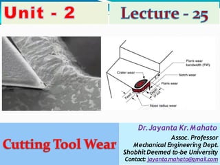
6. Classification of tool wear
The tool wares are classified into the following types:
1. Crater wear on tool face
2. Flank wear
3.Localized wear such as the rounding of Cutting edge
(Nose wear/Corner wear)
4. Chipping of the cutting edge
7. Crater Wear
It consists of a cavity or concave section
on the tool face/rake face formed and
grows from the action of the chip sliding
against the surface.
High stresses and temperatures
characterize the tool–chip contact
wearing
interface, contributing to the
action.
The crater can be measured either by its
depth or its area.
Crater wear affects the mechanics of the
process increasing the actual rake angle
of the cutting tool and consequently,
making cutting easier.
At the same time, the crater wear
weakens the tool wedge and increases
the possibility for tool breakage.
This wear predominates at high speed. In
general, crater wear is of a relatively
small concern.
8. Causes of Crater Wear
The crater wear is mainly
caused due to:
□The presence of friction
between the chip-tool interface,
□The abrasion action of
microchips present at the chip-
tool interface.
□The abrasive action of
fragments of Built up Edge (BUE)
at the chip-tool interface and
diffusion wear.
□The diffusion wears, due to the
atomic attraction between the
tool and work the atoms of the
tool material will get diffused and
deposited over the work piece
called diffusion wear.
9. Flank Wear
It occurs on the tool flank as a result of friction between
the machined surface of the work piece and the tool flank.
Flank wear appears in the form of so-called wear land and
is measured by the width of this wear land, VB.
Flank wear affects to the great extend the mechanics of
cutting.
An extreme condition of flank wear often appears on the
cutting edge at the location corresponding to the original
surface of the workpart. This is called notch wear. It
occurs because the original work surface is harder and/or
more abrasive than the internal material, which could be
caused by work hardening from cold drawing or previous
machining, sand particles in the surface from casting, or
other reasons. As a consequence of the harder surface,
wear is accelerated at this location.
Cutting forces increase significantly with flank wear. If the
amount of flank wear exceeds some critical value (VB >
0.5~0.6 mm) then the excessive cutting force may cause
tool failure.
This wear predominates at low speed.
10. Causes of Flank Wear
work
The flank wear is mainly caused due to:
□ The presence of friction at the tool
interface.
□The abrasive action of microchips or powdered
particles present at the tool work interface and
diffusion wear.
□The diffusion wears, due to the atomic
attraction between the tool and work the atoms
of the tool material will get diffused and
deposited over the workpiece called as diffusion
wear.
Dr. Jayanta Kr. Mahato, Asst. Prof., Mechanical Engineering10
11. Corner wear or nose Wear
It occurs on the tool corner.
□It can be considered as a part of the wear land and
respectively flank wear since there is no distinguished
boundary between the corner wear and flank wear land.
□We consider corner wear as a separate wear type
because of its importance for the precision of machining.
□Corner wear actually shortens the cutting tool thus
increasing gradually the dimension of machined surface
and introducing a significant dimensional error in
machining, which can reach values of about 0.03~0.05 mm.
14. Control of Tool Wear
The rate of tool wear strongly
depends on the cutting
temperature; therefore any
measures which could be
applied to reduce the cutting
temperature would reduce the
tool wear as well.
Use of cutting fluids,
lubricants is another method.
Additional measures to reduce
the tool wear include the
application of advanced
cutting tool materials, such as
coated carbides, ceramics,
etc.
The figure shows the process
parameters that influence the
rate of tool wear:
Dr. Jayanta Kr. Mahato, Asst. Prof., Mechanical Engineering