Downloaded 737 times
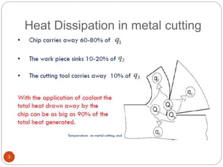
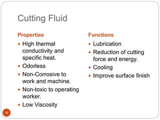
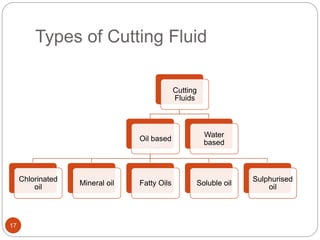
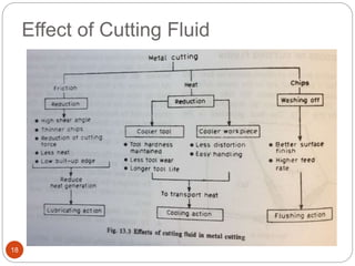
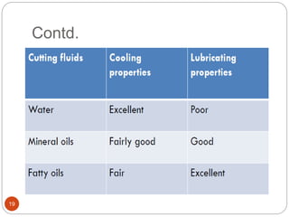


The document discusses the critical role of heat in metal cutting, emphasizing that a significant portion of mechanical energy is converted into thermal energy, impacting tool wear, life, and the integrity of the workpiece. It outlines heat generation sources, temperature effects on tools, and strategies for temperature control, including the use of cutting fluids. Types and properties of cutting fluids are also described as they play a vital role in cooling, lubrication, and improving surface finish.