Downloaded 1,058 times

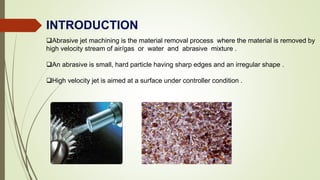
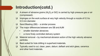
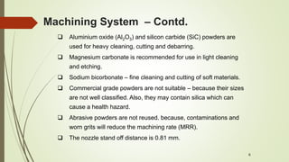
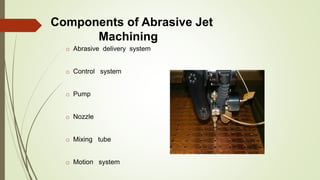
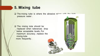
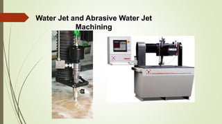
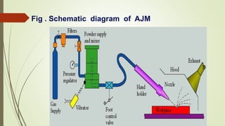
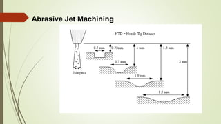
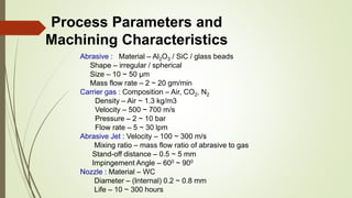
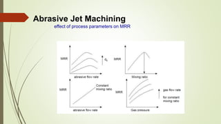
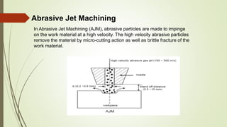
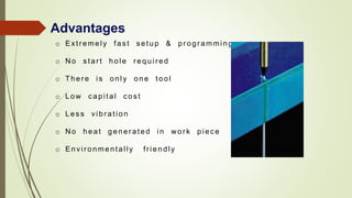


Abrasive jet machining uses a high-pressure stream of abrasive particles carried by gas or water to erode material from a workpiece. Key components include an abrasive delivery system, control system, pump, nozzle, and motion system. It can precisely cut hard materials like ceramics and glass. While removal rates are slower than other machining methods, AJM requires no start holes and generates minimal heat or vibration in the workpiece.


![Electrical discharge machining [EDM]](https://cdn.slidesharecdn.com/ss_thumbnails/electricaldischargemachiningedm-170803232011-thumbnail.jpg?width=640&height=640&fit=bounds)


