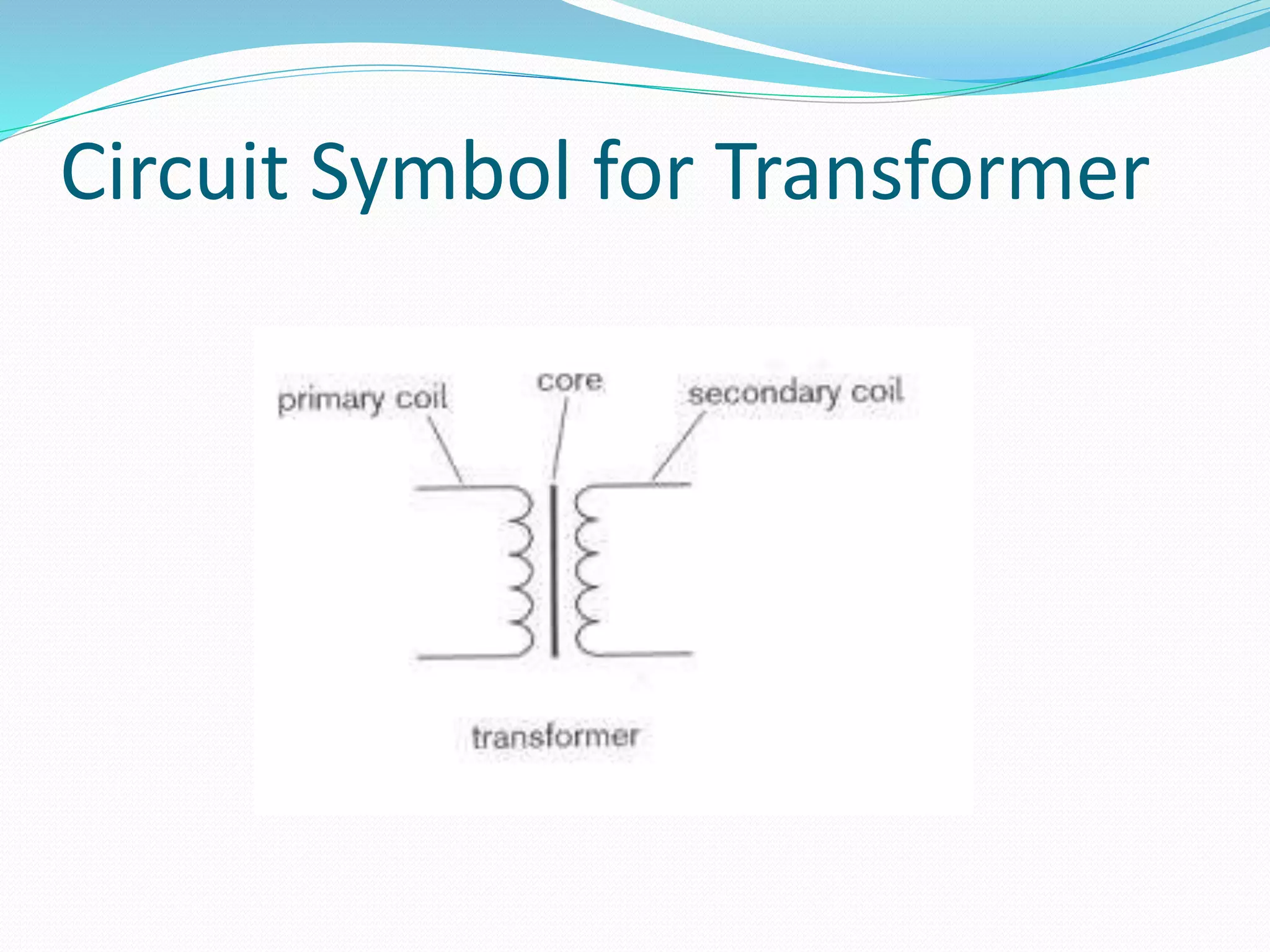
Construction and their working
What is transformer?
 A transformer is an electric device which is used for
changing the a.c. voltages and to render the current
earth-free
 A transformer which increase voltages is called as
step up transformer
 A transformer which decrease voltages is called as
step down transformer
 Principle: based on the principle of mutual induction
Circuit Symbol for Transformer
Construction of transformer
 Consist of two coils (primary
and secondary) of insulated wire
wound onto a laminated soft iron
frame
 Two coils may be wound on top
of one another on central bar or
on opposite side of the frame
 Frame is usually rectangular in
shape
 One coil usually contain more
turns than other
Working of Transformer
 An alternating current is passed through primary coil
which sets up magnetic field which cut the secondary coil
 Emf is induced in secondary coil due to change in
magnetic field of primary coil
 For an emf to be induced, current should be a.c.
 No electrical connection b/w two coils both are insulated
from each other, current is induced via EMI
 Soft iron core serves to concentrate the mag. lines of
forces
 Soft iron is laminated to prevent eddy currents
 Step up transformer: No. of turns in primary coil is less
than that in secondary coil
 Converts the low voltages into high voltages
 Primary coil is made of thick insulated copper wire with
less no. of turns
 Secondary coil is made of thin insulated copper wire with
larger no. of turns
 Step down transformer: No. of turns in primary coil is
larger than that in secondary coil
 Converts the high voltages into low voltages
 Secondary coil is made of thick insulated copper wire with
less no. of turns
 Primary coil is made of thin insulated copper wire with
larger no. of turns
Function of Transformer
 To render the current earth free: The main current
passes through primary coil induces emf in secondary coil,
as there is no elec. connection b/w primary and secondary
coil, which has no connection to earth so render the
current earth free
 If connection b/w earth and sec. coil made, no current
passes to earth as circuit is not complete, so no earth
shock occur
 To alter the voltage of an alternating current: via step
up and step down transformer
 Emf induced in secondary coil is directly proportional to
no. of turns in this coil
Types of transformer
 Static transformer (step up, step down and even ratio
transformer)
 Variable transformer
 Autotransformer
Variable transformer
 That can put out different amount of voltage from the same
input voltage
 Tapings may be provided so that either primary or secondary
coil can be varied in length
 To use the same apparatus on supply of different voltages by
varying no. of turns
 Higher the voltage of supply the more turns of wire are
included in primary coil
 Care should be taken to see that control is in right position for
supply used
 Tapings may be taken from different points on secondary coil
to supply different voltages to separate circuits in same
apparatus
 Used to speed up and slow down electric motor
 Make lights dimmer and brighter
Autotransformer
 Consist of a single coil of insulated wire wound over
laminated soft iron core
 Tapped at two points, C and D
 When used as a step up transformer , coil b/w C and D act
as primary and A and B act as secondary and vice versa
 It has certain disadvantages
 It can be used only for a small step up and down in
voltage
 Do not make current earth free in secondary coil
Choke coil
 It is included in circuit in order to produce a self induced EMF
 Low frequency choke coil: consist of many turns of insulated
wire wound on soft iron usually on central bar of rectangular
frame
 High frequency choke coil: consist of usually less no. of turns
of insulated wire wound on bobbin of non conducting material
as current varies rapidly
Uses:
 Even out variations in the intensity of current
 To prevent the flow of high frequency current and allow the
passage of lower one
Dynamo
 It is a device which is used for the production of an EMF
via electromagnetic induction
Construction
 A coil of wire lie b/w poles of magnet and by some mean
rotation of the coil is provided via motor, steam engine or
water power
 When coil rotates, emf is induced in coil first in one
direction than other
 So current produced is alternating type
 Collecting device is used to convey current from coil to
external circuit
 Supply both types of currents to external circuit either
a.c or by converting a.c into d.c
 Used on large scale for production of electricity
including main supply

Transformers

  • 1.
  • 2.
    What is transformer? A transformer is an electric device which is used for changing the a.c. voltages and to render the current earth-free  A transformer which increase voltages is called as step up transformer  A transformer which decrease voltages is called as step down transformer  Principle: based on the principle of mutual induction
  • 3.
    Circuit Symbol forTransformer
  • 4.
    Construction of transformer Consist of two coils (primary and secondary) of insulated wire wound onto a laminated soft iron frame  Two coils may be wound on top of one another on central bar or on opposite side of the frame  Frame is usually rectangular in shape  One coil usually contain more turns than other
  • 5.
    Working of Transformer An alternating current is passed through primary coil which sets up magnetic field which cut the secondary coil  Emf is induced in secondary coil due to change in magnetic field of primary coil  For an emf to be induced, current should be a.c.  No electrical connection b/w two coils both are insulated from each other, current is induced via EMI  Soft iron core serves to concentrate the mag. lines of forces  Soft iron is laminated to prevent eddy currents
  • 6.
     Step uptransformer: No. of turns in primary coil is less than that in secondary coil  Converts the low voltages into high voltages  Primary coil is made of thick insulated copper wire with less no. of turns  Secondary coil is made of thin insulated copper wire with larger no. of turns  Step down transformer: No. of turns in primary coil is larger than that in secondary coil  Converts the high voltages into low voltages  Secondary coil is made of thick insulated copper wire with less no. of turns  Primary coil is made of thin insulated copper wire with larger no. of turns
  • 8.
    Function of Transformer To render the current earth free: The main current passes through primary coil induces emf in secondary coil, as there is no elec. connection b/w primary and secondary coil, which has no connection to earth so render the current earth free  If connection b/w earth and sec. coil made, no current passes to earth as circuit is not complete, so no earth shock occur  To alter the voltage of an alternating current: via step up and step down transformer  Emf induced in secondary coil is directly proportional to no. of turns in this coil
  • 9.
    Types of transformer Static transformer (step up, step down and even ratio transformer)  Variable transformer  Autotransformer
  • 10.
    Variable transformer  Thatcan put out different amount of voltage from the same input voltage  Tapings may be provided so that either primary or secondary coil can be varied in length  To use the same apparatus on supply of different voltages by varying no. of turns  Higher the voltage of supply the more turns of wire are included in primary coil  Care should be taken to see that control is in right position for supply used  Tapings may be taken from different points on secondary coil to supply different voltages to separate circuits in same apparatus
  • 11.
     Used tospeed up and slow down electric motor  Make lights dimmer and brighter
  • 12.
    Autotransformer  Consist ofa single coil of insulated wire wound over laminated soft iron core  Tapped at two points, C and D  When used as a step up transformer , coil b/w C and D act as primary and A and B act as secondary and vice versa  It has certain disadvantages  It can be used only for a small step up and down in voltage  Do not make current earth free in secondary coil
  • 14.
    Choke coil  Itis included in circuit in order to produce a self induced EMF  Low frequency choke coil: consist of many turns of insulated wire wound on soft iron usually on central bar of rectangular frame  High frequency choke coil: consist of usually less no. of turns of insulated wire wound on bobbin of non conducting material as current varies rapidly Uses:  Even out variations in the intensity of current  To prevent the flow of high frequency current and allow the passage of lower one
  • 15.
    Dynamo  It isa device which is used for the production of an EMF via electromagnetic induction Construction  A coil of wire lie b/w poles of magnet and by some mean rotation of the coil is provided via motor, steam engine or water power  When coil rotates, emf is induced in coil first in one direction than other  So current produced is alternating type  Collecting device is used to convey current from coil to external circuit
  • 16.
     Supply bothtypes of currents to external circuit either a.c or by converting a.c into d.c  Used on large scale for production of electricity including main supply